Week-7 Challenge: DC Motor Control
Q.1) A. Explain a MATLAB demo model named ‘Speed control of a DC motor using BJT H-bridge’.
The given model is for speed control of DC motor using BJT H-Bridge.
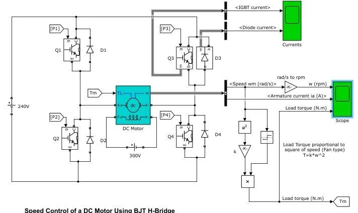
The Bipolar Junction Transistor (BJT) when used for power switching applications, operates as an IGBT. When it is conducting (BJT operating in the saturated region), a forward voltage Vf is developed between collector and emitter (in the range of 1 V). Therefore, the IGBT block can be used to model the BJT device.
The four IGBT and diode pairs Q1-D1, Q2-D2, Q3-D3 and Q4-D4 form the H-Bridge. A DC motor (5 HP 240V 1750 rpm) is connected in the given model. A 240VDC supply is used in this model. The field winding of the motor is supplied with a 300 VDC supply.
Two transistors are switched simultaneously: Q1 and Q4 or Q2 and Q3. When Q1 and Q4 are fired, a positive voltage is applied to the motor and diodes D2-D3 operate as free-wheeling diodes when Q1 and Q4 are switched off. When Q2 and Q3 are fired, a negative voltage is applied to the motor and diodes D1-D4 operate as free-wheeling diodes when Q2 and Q3 are switched off.
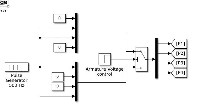
A combination of pulse generator, MUX, switch block and DEMUX is used to fired the transistors. For first 0.5 seconds transistors Q1 and Q4 are fired. While for next 0.5 seconds transistors Q2 and Q3 are fired.
We know that for a fan load torque is directly proportional to the square of the angular speed. k is the constant of proportionality. Angular speed is converted to load torque square, gain and product block. As shown in the figure.
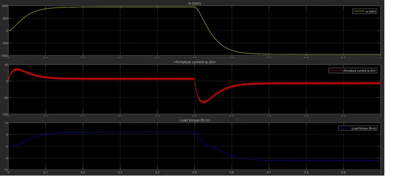
B) Comment on the armature current shoot-up from the scope results.
We have equation for back EMF,
Eb = V – IaRa …………(1)
We know that back EMF is directly proportional to the speed.
Eb α ω
So, at starting when speed is zero, the back EMF is also zero.
Thus, if we refer equation (1) V and Ra are constant. Hence to make Eb zero Ia increases.
So at starting of the DC motor armature current shoots up and it decreases with increase in the speed.
C)Refer to the help section of ‘The Four-Quadrant Chopper DC Drive (DC7) block’. Compare it with the H-bridge model.
Four quadrant chopper-
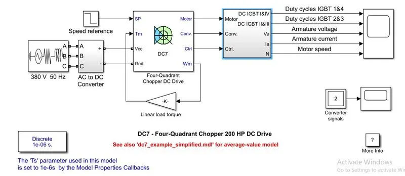
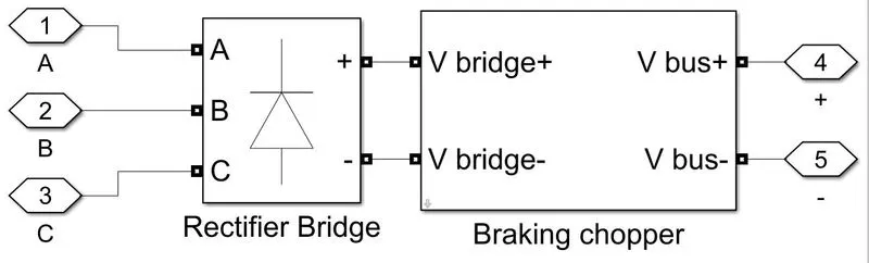
The 200 HP DC motor is separately excited with a constant 150 V DC field voltage source. The armature voltage is provided by an IGBT converter controlled by two PI regulators. The converter is fed by a 515 V DC bus obtained by rectification of a 380 V AC 50 Hz voltage source. In order to limit the DC bus voltage during dynamic braking mode, a braking chopper has been added between the diode rectifier and the DC7 block.
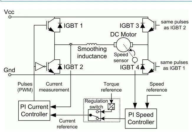
The first regulator is a speed regulator, followed by a current regulator. The speed regulator outputs the armature current reference (in p.u.) used by the current controller in order to obtain the electromagnetic torque needed to reach the desired speed. The speed reference change rate follows acceleration and deceleration ramps in order to avoid sudden reference changes that could cause armature over-current and destabilize the system. The current regulator controls the armature current by computing the appropriate duty ratios of the 5 kHz pulses of the four IGBT devices (Pulse Width Modulation). For proper system behaviour, the instantaneous pulse values of IGBT devices 1 and 4 are opposite to those of IGBT devices 2 and 3. This generates the average armature voltage needed to obtain the desired armature current. In order to limit the amplitude of the current oscillations, a smoothing inductance is placed in series with the armature circuit.
The Four-Quadrant Chopper DC Drive (DC7) block represents a four-quadrant, DC-supplied, chopper (or DC-DC PWM converter) drive for DC motors. This drive features closed-loop speed control with four-quadrant operation. The speed control loop outputs the reference armature current of the machine. Using a PI current controller, the chopper duty cycle corresponding to the commanded armature current is derived. This duty cycle is then compared with a sawtooth carrier signal to obtain the required PWM signals for the chopper.
The main advantage of this drive, compared with other DC drives, is that it can operate in all four quadrants (forward motoring, reverse regeneration, reverse motoring, and forward regeneration). In addition, due to the use of high switching frequency DC-DC converters, a lower armature current ripple (compared with thyristor-based DC drives) is obtained. However, four switching devices are required, which increases the complexity of the drive system.
H-Bridge-
The Bipolar Junction Transistor (BJT) when used for power switching applications, operates as an IGBT. When it is conducting (BJT operating in the saturated region), a forward voltage Vf is developed between collector and emitter (in the range of 1 V). Therefore, the IGBT block can be used to model the BJT device.
The IGBT block does not simulate the gate current controlling the BJT or IGBT. The switch is controlled by a Simulink® signal (1/0). The DC motor uses the present model (5 HP 240V 1750 rpm). It simulates a fan type load (where Load torque is proportional to square of speed). The armature mean voltage can be varied from 0 to 240 V when the duty cycle (specified in the Pulse Generator block) is varied from 0 to 100%.
The H-bridge consists of four BJT/Diode pairs (BJT simulated by IGBT models). Two transistors are switched simultaneously: Q1 and Q4 or Q2 and Q3. When Q1 and Q4 are fired, a positive voltage is applied to the motor and diodes D2-D3 operate as free-wheeling diodes when Q1 and Q4 are switched off. When Q2 and Q3 are fired, a negative voltage is applied to the motor and diodes D1-D4 operate as free-wheeling diodes when Q2 and Q3 are switched off.
Q2.Develop a 2-quadrant chopper using simulink & explain the working of the same with the relevant results.
Basic concept of 2 quadrant chopper-
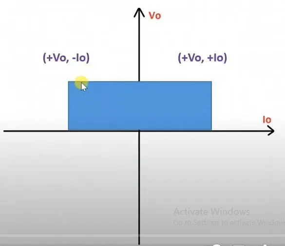
- Class C chopper is a 2 quadrant chopper.
- Functions in 1st and 2nd
- Output voltage is always positive and output voltage can be negative or positive. (Positive in 1st quadrant and negative in 2nd quadrant)
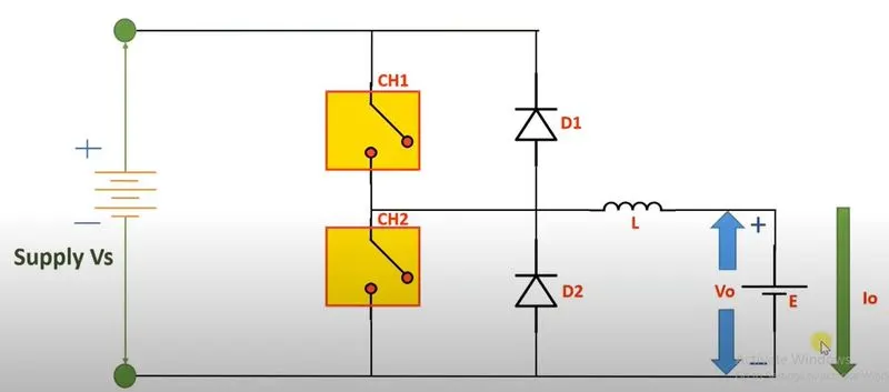
In C type chopper a volage source (Vs) is used. There are two choppers CH1 and CH2. Also diodes D1 and D2 are connected in the circuit as shown. An inductor is connected in series with the load, where load is an EMF E. The polarity and the direction of output current is as shown in the diagram.
1st Quadrant Operation-
For 1st quadrant operation chopper CH1 or Diode D2 is on.
- When CH1 is ON-
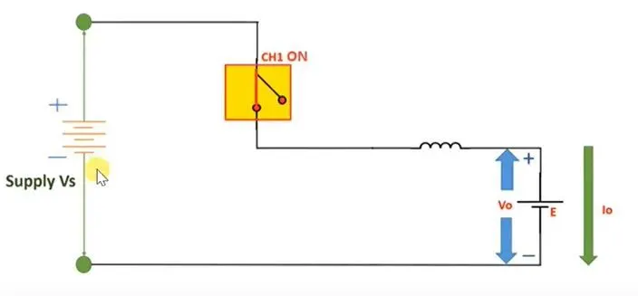
The following figure shows circuit diagram of chopper when CH1 is ON. As we can see when CH1 is ON current flows from source to load. At the same time series connected inductor will get charged.
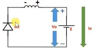
When CH1 is OFF, the inductor changes its polarity to discharge power stored in it. As shown in figure current flows through D2 and in positive direction.
- When CH2 is ON-
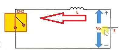
The following figure shows circuit diagram of chopper when CH2 is ON. As we can see when CH2 is ON current flows from load to source. At the same time series connected inductor will get charged.
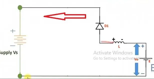
When CH2 is OFF, the inductor changes its polarity to discharge power stored in it. As shown in figure current flows through D1 and in negative direction.
Model explanation-
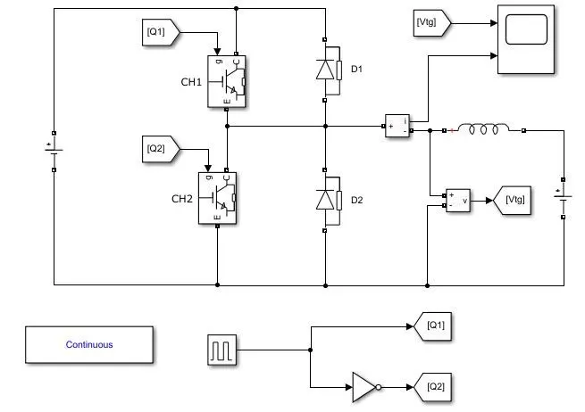
Blocks used-
- DC voltage source
- IGBT
- Diode
- Voltage measurement
- Current Measurement
- Pulse Generator
- Power GUI block
- Scope
Figure shows the required Simulink model for 2 quadrant chopper.
For channel 1 and 2 IGBTs are used. A DC voltage source is used to supply the load. The voltage is set as 24 V for V0. Another DC voltage source is used as load. An inductor is connected is series with the load.
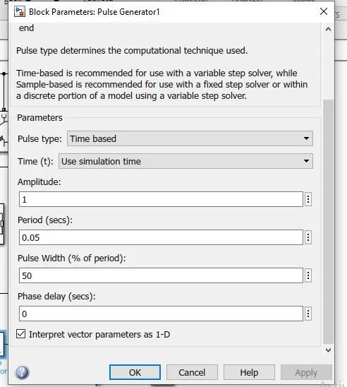
A pulse generator is used to fire the to IGBTs as shown in figure. The amplitude, period and duty cycle is set as 1, 0.05 sec and 50 % respectively.
Observation-
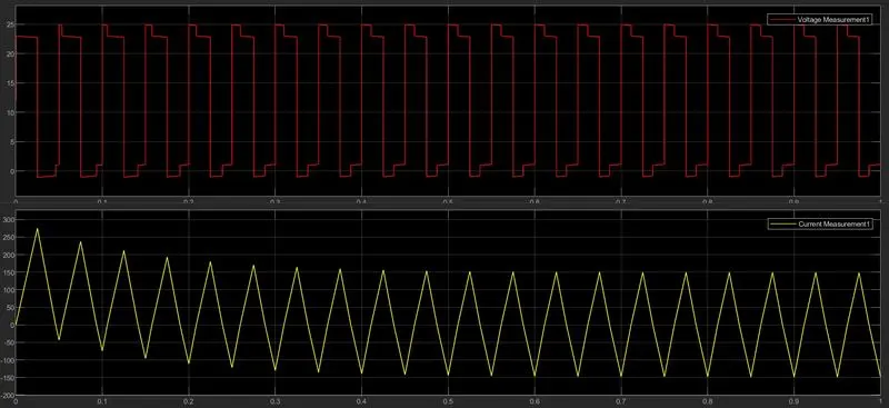
As observed from the result, the output voltage rises up to 24 volts. At the same time output current rises in positive direction. After 50% of the duty cycle voltage drops to 0 volts value and output currents starts falling and goes in negative region. The output voltage never becomes negative.
So as observed from the result output voltage is always positive. While output current is positive is motoring mode and becomes negative is regenerative mode.
Q3.Explain in a brief about operation of BLDC motor.
In order make operation more reliable, more efficient and less noisy the recent trend has been to used Brushless DC motor(BLDC). They are also lighter compare to brusged DC motors for same power output. Brushes in conventional DC motor wear out over the time and can caused sparking. Thus these motors never be used in applications that demands long life and reliability. Fort this reason and the other reasons listed in the introduction, BLDC motors are used in most of the modern devices. Efficiency of a BLDC motor is typically around 85-90%, whereas the conventional brushed motors are only 75-80% efficient. BLDC motors are also suitable for high speed applications ( 10000 rpm or above). The BLDC motors are also well known for their better speed control.
The basic working
The rotor and sator of a BLDC motor are shown in the Fig.1. It is clear that, the rotor of a BLDC motor is a permanent magnet.
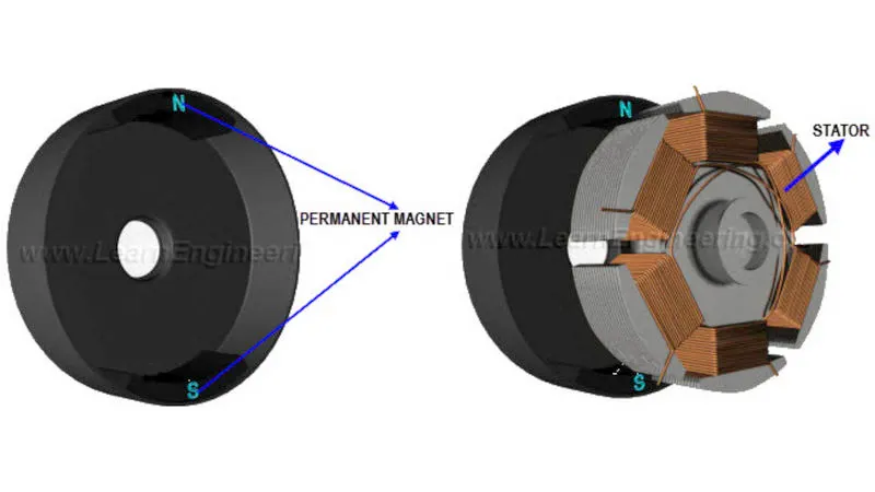
Figure(1)
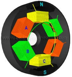
The stator has a coil arrangement, as illustrated; The internal winding of the rotor is illustrated in the Fig.2 (core of the rotor is hidden here). The rotor has 3 coils, named A, B and C.
Figure(2)
Out of these 3 coils, only one coil is illustrated in the Fig.3 :for simplicity. By applying DC power to the coil, the coil will energize and become an electromagnet.
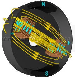
Figure (3)
The operation of a BLDC is based on the simple force interaction between the permanent magnet and the electromagnet. In this condition, when the coil A is energized, the opposite poles of the rotor and stator are attracted to each other (The attractive force is shown in green arrow). As a result the rotor poles move near to the energized stator.
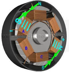
Figure (4)
As the rotor nears coil A, coil B is energized. As the rotor nears coil B, coil C is energized. After that, coil A is energized with the opposite polarity (compare the last part of Fig.5 with Fig.4).
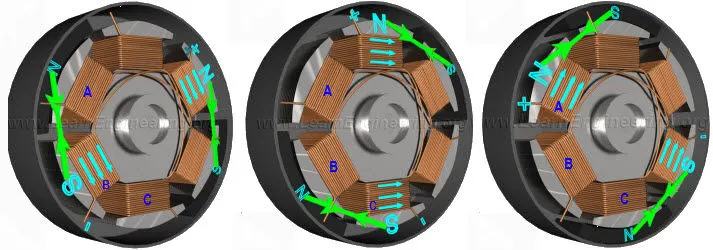
Figure (5)
his will make the rotor continuously rotate This process is repeated, and the rotor continues to rotate. The DC current required in the each coil is shown in the following graph.
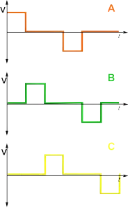
Figure (6)
Further improving the BLDC performance
Even though this motor works, it has one drawback. You can notice that, at any instant only one coil is energized. The 2 dead coils greatly reduce the power output of the motor. Here is the trick to overcome this problem. When the rotor is in this position, along with the first coil, which pulls the rotor, you can energize the coil behind it such a way that, it will push the rotor.
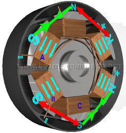
Figure (7)
this will result in a push force apart from the pull force
For this instant, a same polarity current is through the second coil. The combined effect produces more torque and power output from the motor. The combined force also makes sure that a BLDC has a beautiful, constant torque nature. Such torque nature is difficult to achieve in any other type of motors.
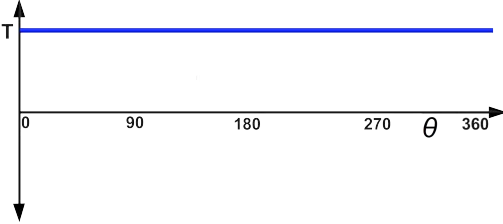
Figure (8)
The current form required for the complete 360 degree rotation is shown in the graph below.
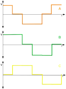
Figure (9)
With this configuration 2 coils need to be energized separately, but by making a small modification to the stator coil, we can simplify this process. Just connect one free end of the coils together, as shown in the Fig.8.
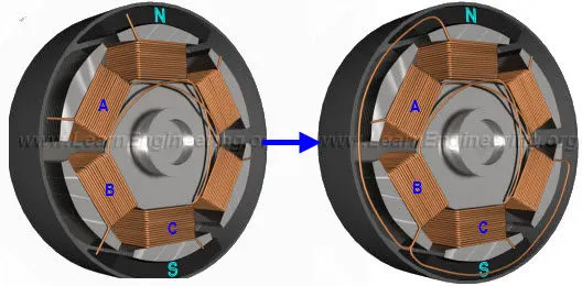
Figure (10)
When the power is applied between coils A and B, let’s note the current flow through the coils. By comparing second part of the Fig11 with Fig.7, it is clear that, the current flow is just like the separately energized state.
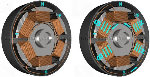
Figure (11)