Project 2 Adaptive Cruise Control
Aim- To create a Simulink model for ADAS- Adaptive Cruise Control System as per given requirements.
Objectives-
- To create Simulink model for the given requirements.
- Create Simulink data dictionary and link it with the Simulink model.
- Set various configuration parameters such as solver settings, code generation, coverage, etc.
- Run model advisor test and make changes accordingly.
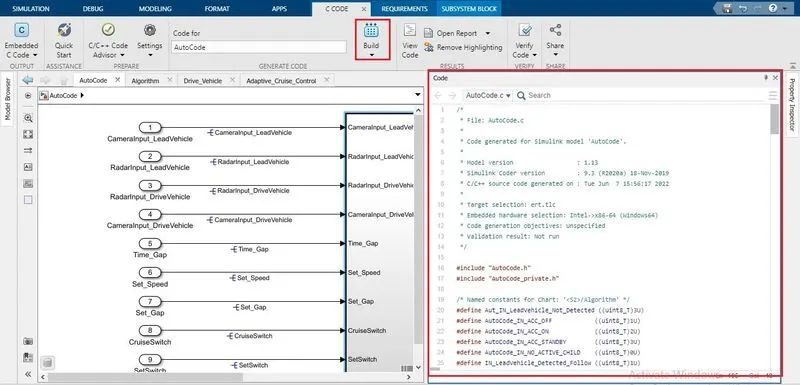
- Generate the C code.
Model Explanation-
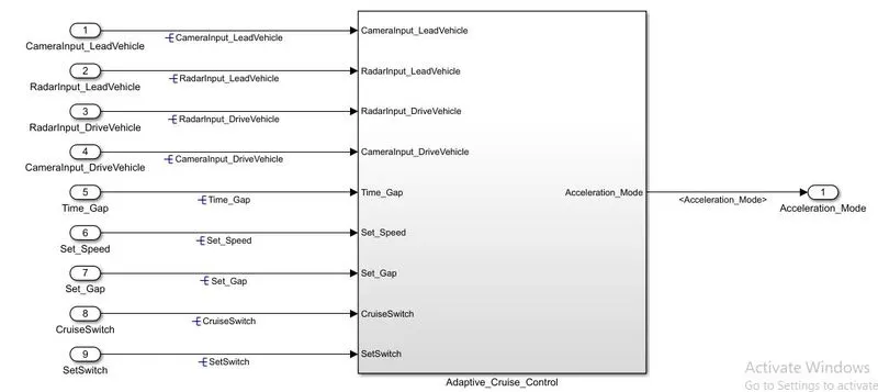
Above figure shows the desired model for the given requirements. This model has total 9 inputs- CameraInput_LeadVehicle, RadarInput_LeadVehicle, RadarInput_DriveVehicle, CameraInput_DriveVehicle, Time_Gap, Set_Speed, Set_Gap, CruiseSwitch & SetSwitch. . Further there are 3 requirements. Thus, given model is further divided into 3 subsystems- Lead_Vehicle, Drive_Vehicle & ACC_Algorithm.
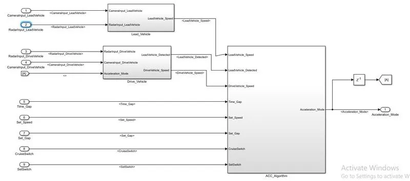
Requirement 1(Lead Vehicle)-
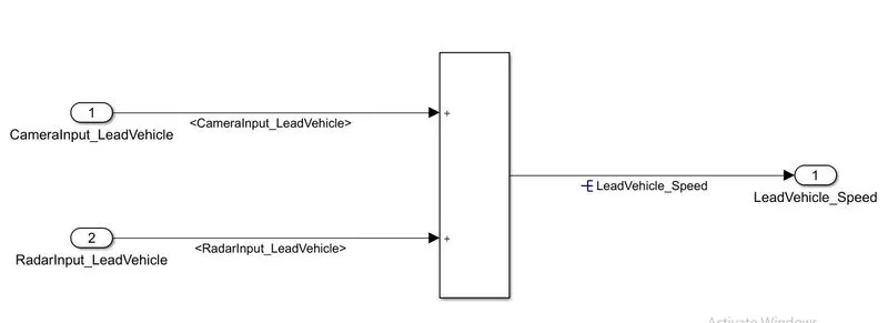
Blocks used-
- Add block
Model Explanation-
This requirement has 2 inputs- CameraInput_LeadVehicle & RadarInput_LeadVehicle. The data type for this two signals is uint8. Here this 2 inputs are simply added and corresponding output is simply read as speed profile output.
Requirement 2(Drive vehicle)-
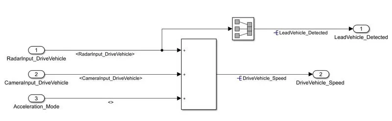
Blocks used-
- Add block
- Signal conversion block
Model Explanation-
Drive Vehicle algorithm also has 2 input signals (Signal Name: CameraInput_DriveVehicle, RadarInput_DriveVehicle) & one signal coming as an Input to this subsystem (Signal Name: Acceleration_Mode) – three inputs into this requirement in total. Two output signals come from this subsystem (Signal Name: DriveVehicle_Speed & LeadVehicle_Detected). Signal DriveVehicle_Speed is summation of three input signals. LeadVehicle_Detected is renamed from Input Signal RadarInput_DriveVehicle by mere use of Signal Conversion block.
Requirement 3(Adaptive Cruise control Algorithm)-
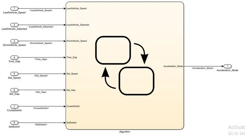
Model Explanation-
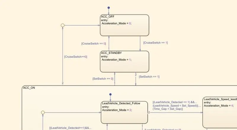
This requirement is implemented as state machine logic in Simulink. Adaptive Cruise Control feature has 3 major modes of operation: OFF Mode, STANDBY Mode & ON Mode.
ACC_OFF is the default transition state. In this state output signal Acceleration_Mode is at value 0.
The 2nd state is ACC_STANDBY state. In this state the value of output signal Acceleration_Mode is at 1.
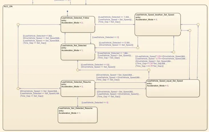
The last state is ACC_ON state. This state has 6 substates.
- LeadVehicle_Detected_Follow (Default)
- LeadVehicle_Not_Detected
- LeadVehicle_Detected_Resume
- LeadVehicle_Not_Detected_Resume
- LeadVehicle_Speed_lessthan_Set_Speed
- LeadVehicle_Speed_equal_Set_Speed
Steps-
Creating SLDD-
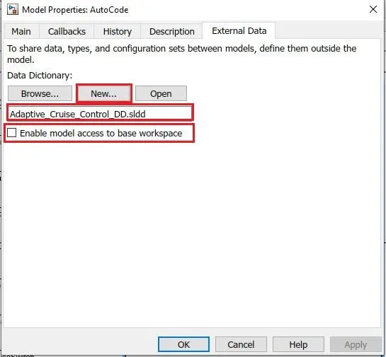
- Go to model properties > external data
- Click on New
- Enter the SLDD name
- Uncheck Enable model access to base workspase
- Click apply and then OK
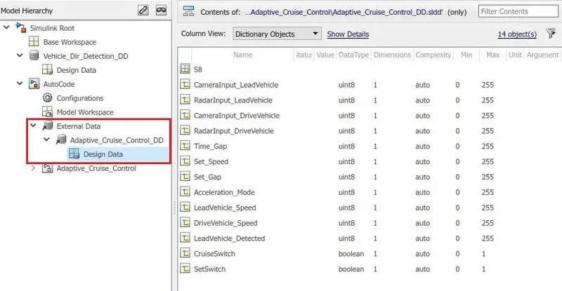
- Now open model explorer
- From model hierarchy go to External data > Adaptive_Cruise_Control_dd > Design Data
- Enter all the input, output and localize signals here.
Configuration Parameters settings-
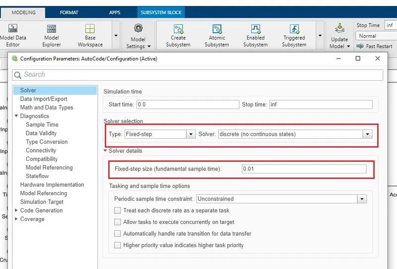
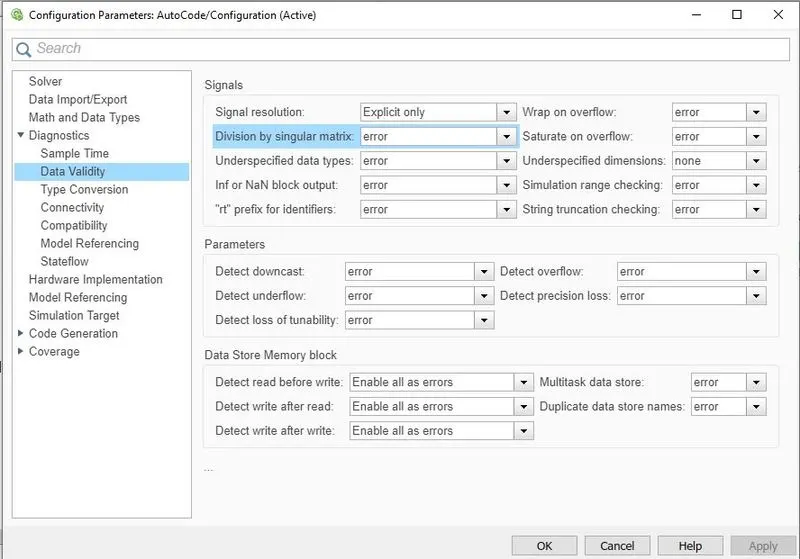
- Open Configuration parameters
- Go to Solver
- Select Solver Type as Fixed Step and Solver as discrete. Enter Step size as 0.01
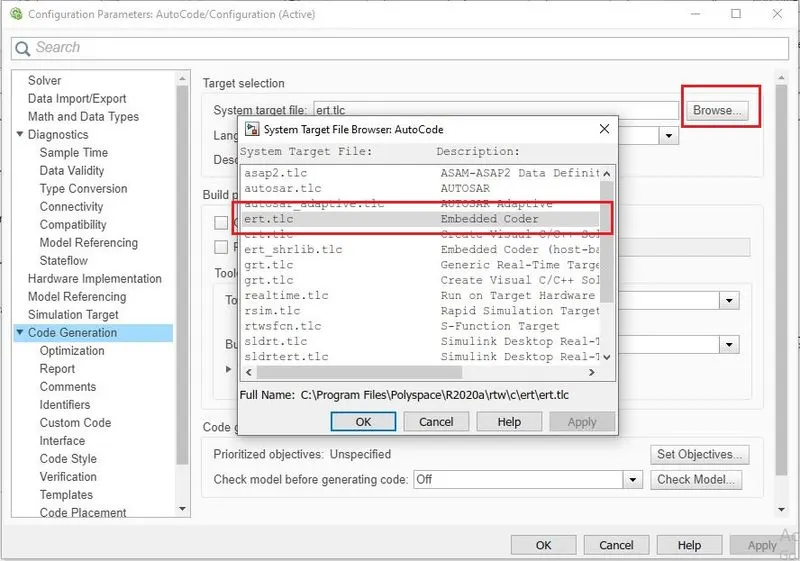
- Go to Code Generation
- Browse system target file > select ert.tlc
- Apply > OK
Requirement Tagging-
- Right Click on Adaptive_Cruise_Control subsystem
- Go to requirements > Link to Selection In word
Model Advisor Test-
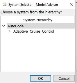
- Open model advisor
- Select Autocode from system hierarchy and click OK
- Check Modeling standard for ISO 26262, Code generation Efficiency, Model Referencing, etc.
- Click Run selected checks.
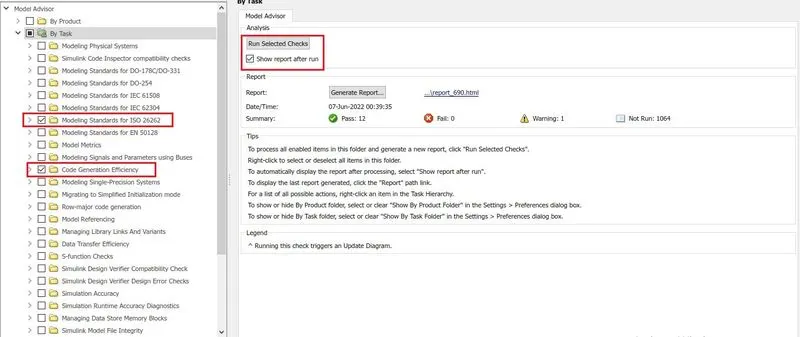
- After check is completed resolve the warnings and errors.
Code Generation-
- Right Click on Adaptive_Cruise_Control subsystem
- Check Treat as atomic unit
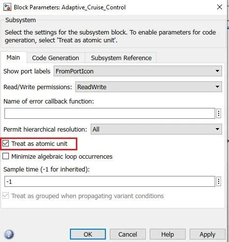
- Go to C Code tab
- Generate code.