Project 1 (Mini Project on Vehicle Direction Detection
Aim: Creating a Simulink model for ADAS feature- Vehicle direction detection as per given requirements.
Objectives-
- To create Simulink model for the given requirements.
- Create Simulink data dictionary and link it with the Simulink model.
- Set various configuration parameters such as solver settings, code generation, coverage, etc.
- Run model advisor test and make changes accordingly.
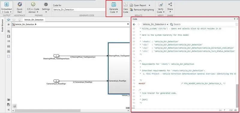
- Generate the C code.
Model Explanation-
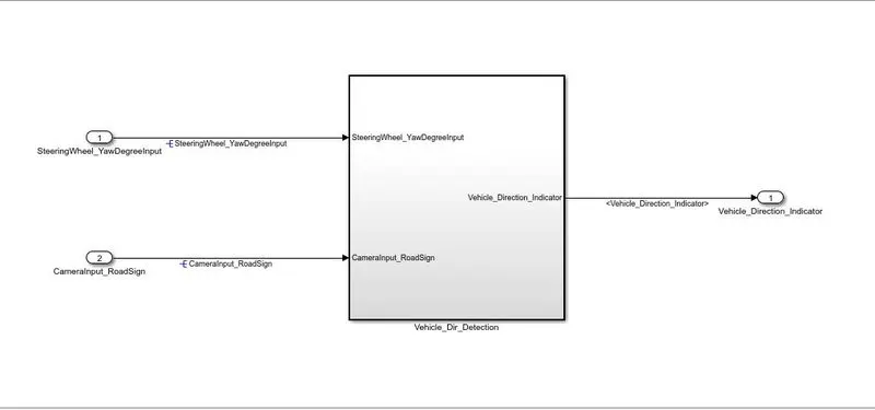
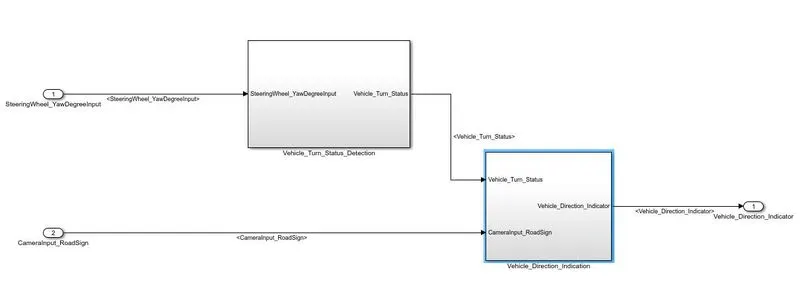
The above figure shows the desired model for the given requirements. This model has two inputs- Steering wheel yaw degree & camera input road sign. There are two requirements as per requirement document. Thus, this model is further divided in two sub systems as given in figure two. First subsystem is for vehicle turn status detection and second system is for vehicle direction detection.
Requirement 1-
Blocks used-
- Relation operator
- Constant block
- Switch block
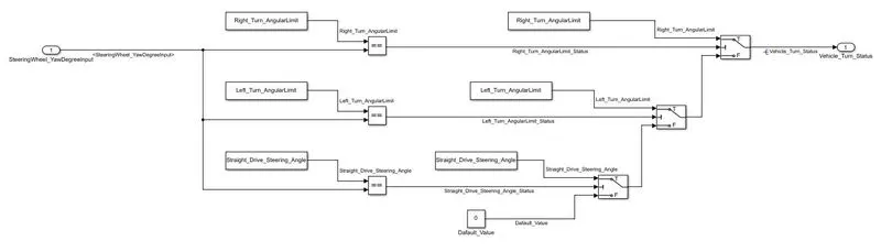
This subsystem is for vehicle turn status detection. The input for this subsystem is Steering wheel yaw degree. Steering wheel yaw degree is compare with 3 calibration values- Right_Turn_AngularLimit, Left_Turn_AngularLimit & Straight_Drive_Steering_Angle. If steering wheel yaw degree is equal to any of this calibration values then respective switch block passes the angular limit associated with that calibration value. If steering wheel yaw degree is not equal to any of the calibration parameters then , the switch block passes the default zero value. The output of the subsystem vehicle turn status detection is vehicle turn status signal.
Requirement 2-
Blocks used-
- Relation operator
- Constant block
- Logical operator
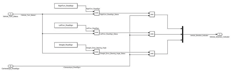
This subsystem is for vehicle direction indication. The inputs for this subsystem are road sign input from camera and vehicle turn status signal from subsystem 1. The vehicle turn status is compared with three calibration values RightTurn_RoadSign, LeftTurn_RoadSign & Straight_RoadSign. If vehicle turn status is equal to one of the calibration values then the equal to operator gives the output as 1. The road sign camera input gives input as 1 when it detects a road sign. This two signals are compared with help of a logical AND operator. If both the signals are 1 the logical AND operator gives output as 1 i.e. it gives the direction in which vehicle is taking the turn.
Steps-
Creating SLDD-
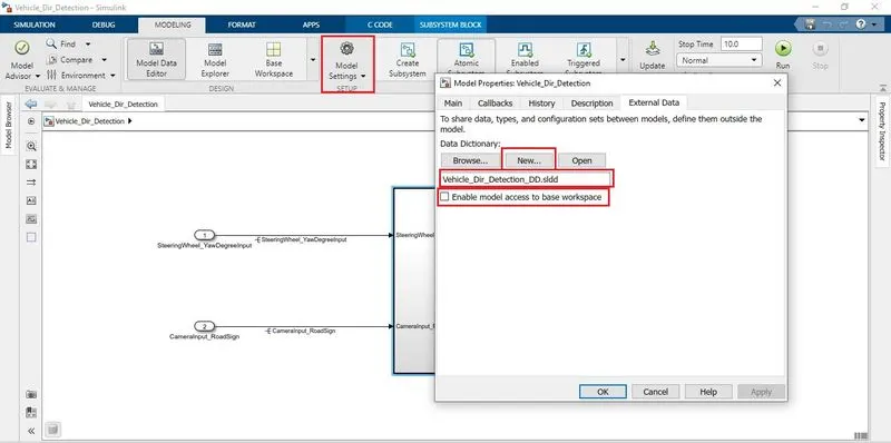
- Go to model properties > external data
- Click on New
- Enter the SLDD name
- Uncheck Enable model access to base workspase
- Click apply and then OK
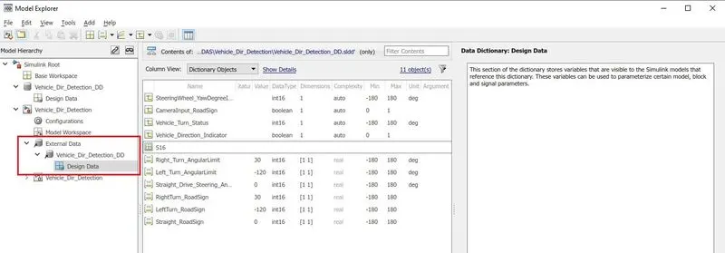
- Now open model explorer
- From model hierarchy go to External data > Vehicle_dir_Detection_dd > Design Data
- Enter all the input, output and localize signals here.
Configuration Parameters settings-
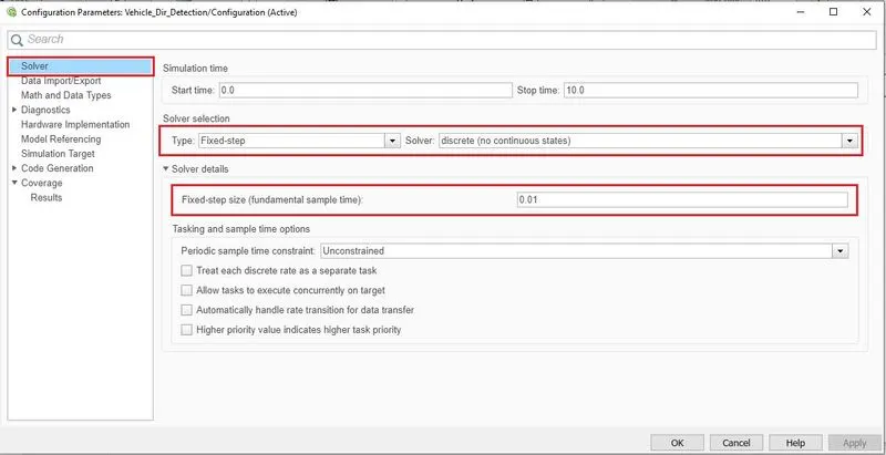
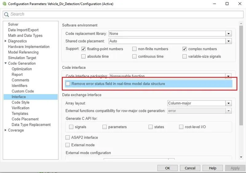
- Open Configuration parameters
- Go to Solver
- Select Solver Type as Fixed Step and Solver as discrete. Enter Step size as 0.01
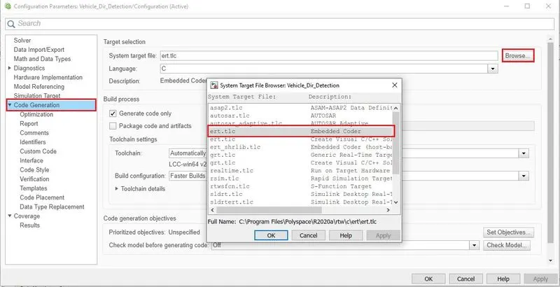
- Go to Code Generation
- Browse system target file > select ert.tlc
- Apply > OK
Requirement Tagging-
- Right Click on Vehicle_Dir_Detection subsystem
- Go to requirements > Link to Selection In word
Model Advisor Test-
- Open model advisor
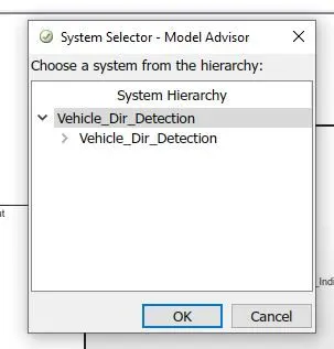
- Select Vehicle_Dir_Detection from system hierarchy and click OK
- Check Modeling standard for ISO 26262, Code generation Efficiency, Model Referencing, etc.
- Click Run selected checks.
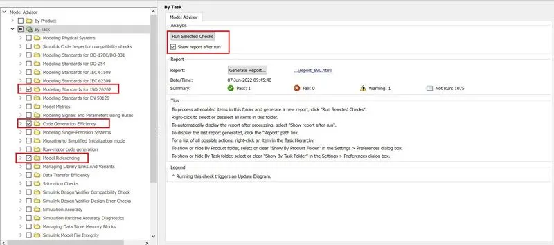
- After check is completed resolve the warnings and errors.
Code Generation-
- Right Click on Vehicle_Dir_Detection subsystem
- Check Treat as atomic unit
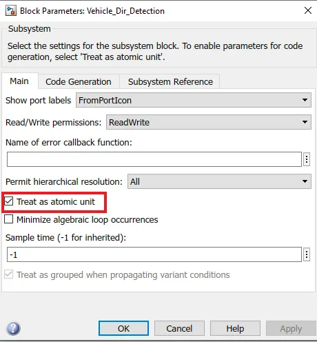
- Go to C Code tab
- Generate code.