Week -2
- Aim: Make a Simulink model of Doorbell using solenoid block.
Working Principle:-
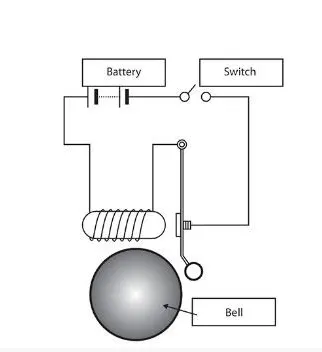
The following diagram of doorbell consist of a solenoid, battery ang a switch. When switch is pressed(Closed circuit) current flows through the solenoid coil and it acts as a magnet. The magnetic field created attracts a flexible plunger. This plunger hits the the bell and makes ringing sound.
Model Explanation:
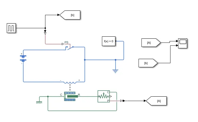
The following model uses following blocks-
- Pulse generator
- Switch
- Battery
- Solenoid
- Ideal translation motion sensor
- Scope
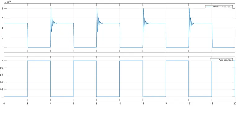
From given condition then switch is closed for 2 seconds and then released. To create this condition a pulse generator is used which create a train of square wave pulses. The value of threshold of switch is 0.8.When external pulse generator value becomes greater than the threshold value the switch closes. A battery and a solenoid coil is connected in the circuit. When switch closes magnetic field gets developed in the solenoid and plunger moved towards C. The moment of the plunger is detected by a translation motion sensor block. A scope is connected at the output of translation motion sensor which displays the position of the plunger.
Aim: Use a thermistor to sense the temperature of a heater & turn on or turn off the fan as per the given conditions.
Working Principle of Thermistors
The thermistor works on the simple principle of change in resistance due to a change in temperature. When the ambient temperature changes the thermistor starts self-heating its elements. its resistance value is changed with respect to this change in temperature. This change depends on the type of thermistor used. The resistance temperature characteristics of different types of thermistors.
NTC Thermistor
NTC stands for Negative Temperature coefficient. They are ceramic semiconductors that have a high Negative Temperature Coefficient of resistance. The resistance of an NTC will decrease with increasing temperature in a non-linear manner.
PTC Thermistor
PTC thermistors are Positive Temperature Coefficient resistors and are made of polycrystalline ceramic materials. The resistance of a PTC will increase with increasing temperature in a non-linear manner. The PTC thermistor shows only a small change of resistance with temperature until the switching point(TR) is reached.
The temperature resistance characteristics of an NTC and a PTC is shown in the following figure.

Model Explanation:
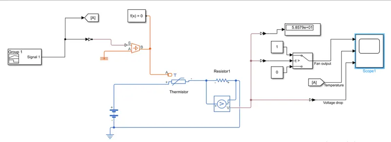
The following model uses following blocks-
- Signal builder
- Controlled temperature source
- NTC thermistor
- Voltage sensor
- Switch
- Scope
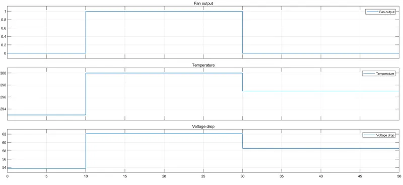
A signal builder produces signals of 293 K(i.e. 20 °C) from 0 to 10 seconds, 300K(27 °C) from 10 to 30 seconds, 297K(23 °C) from 30 to 50 seconds. A controlled temperature source converts this signal into equivalent temperature. Output of this controlled temperature source is given to a NTC thermistor. The nominal resistance of the thermistor is set 1000 ohms at nominal temperature 298.15K(i.e. 25 °C) As resistance of the thermistor changes with the temperature, the current flowing in the circuit also changes. Resistor1(1000ohms) is connected in the circuit to detect the changing temperature value. The voltage drop across the resistor1 changes with the current. A voltage sensor is connected to measure the voltage drop across resistor1. The volage drop across resistor1 at 25 °C is 59.94 volts. The output of the voltage sensor is given to a switch block. The threshold value of the switch block is set at 59.94. When the temperature rises above 25 °C voltage drop across resistor1 becomes more than 59.94 volts. Thus switch block passes the value 1 to its output which resembles fan becomes on. The relation between signal builder, voltage drop across resistor1 and switch block output can be observe using scope.