Project-1: Powertrain for aircraft in runways
Part A-
Q1) Search and list out the total weight of various types of aircrafts.
Aircraft Empty Weight (AEW)
This is sometimes referred to as OEW – Operating Empty Weight and it is the weight of the aircraft with all its equipment on board but no fuel, no passengers or no cargo.
Think of this like the aircraft has just come out of the factory and is sitting waiting to be fueled up for delivery to the customer.
Aircraft Maximum Gross Take off Weight (MGTW)
This is the maximum permissible weight the aircraft can weigh as it lifts off the ground at take off. This includes the aircraft’s empty weight, the fuel, the crew, the passengers, and all the cargo.
This weight limit is set by the manufacturer. Many aircraft accidents have been caused by an aircraft being overweight and the pilot/s have not had enough power or manoeuvrability to prevent the accident.
Aircraft Useful Load
This is the weight that a pilot can place in the aircraft. Take the MGTW figure and subtract the AEW and this is the total useful load that can be placed into the aircraft. This is the fuel, crew, passengers, and cargo. The bigger the load, the more useful the aircraft can be to its customers.
| Aircraft |
Empty Weight |
Max Fuel Weight |
Max Gross Weight |
Max Gross Takeoff Weight |
| Antanov AN-225 | 285000 | 300000 | 190000 | 640000 |
| Airbus A380-800 | 277000 | 254000 | 84000 | 575000 |
| Boeing 747-800 | 220000 | 194000 | 134000 | 447000 |
| Airbus A340-500 | 168000 | 175000 | 54000 | 372000 |
| Boeing 777-300ER | 168000 | 145500 | 67100 | 352000 |
| Boeing 787-900 | 135500 | 101500 | 57300 | 254000 |
| Boeing 737-900 | 44700 | 24000 | 20200 | 85000 |
| Airbus A320-100 | 42600 | 22100 | 20000 | 68000 |
| Embraer 190 | 28800 | 13000 | 13100 | 48000 |
| Gulfstream G650 | 24500 | 21900 | 3000 | 45200 |
|
Bombardier CRJ900 |
21850 | 8900 | 2760 | 36500 |
| Learjet 75 | 6300 | 2750 | 1300 | 9700 |
|
Cessna Citation CJ4 |
4700 | 2650 | 1000 | 7800 |
|
Beachcraft King Air B100 |
3200 | 1450 | 1900 | 5400 |
|
Diamond DA50 RG |
1450 | 155 | 560 | 2000 |
Q2)Is there any difference between ground speed and air speed?
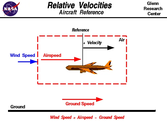
- An aircraft's true airspeed tells us how fast it moves relative to the surrounding air, while the ground speed is its horizontal speed relative to the earth's surface. In still air, an aircraft's ground speed is equal to its true airspeed.
- True airspeed tells the pilots whether the plane is moving fast enough to take off or continue in the air. Ground speed informs the pilots how long they have to flyto reach their destination.
- True airspeed increases with altitude because of less drag, while ground speed does not depend upon how high a plane fly.
Q3)Why is it not recommended to use aircraft engine power to move it on the ground at Airport?
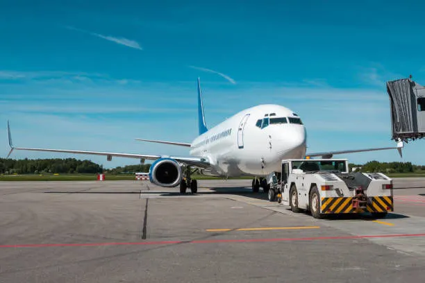
Although many aircraft are capable of moving themselves backward on the ground using reverse thrust (a procedure referred to as a power back), the resulting jet blast or prop wash might cause damage to the terminal building or equipment. Engines close to the ground may also blow sand and debris forward and then suck them into the engine, causing damage to the engine. A towing is therefore the preferred method to move the aircraft away from the gate. Unless the aircraft is in a location where it is unwise to taxi under aircraft power and necessitating a tow by a large tractor, the aircraft’s engine(s) is how the craft moves. Obviously, it is prudent to use only the amount of power to get the airplane moving and then reduce the power for taxiing to avoid high volumes of air spreading debris or damaging other aircraft or ground vehicles.
Jet blast is the phenomenon of rapid air movement produced by the jet engines of aircraft, particularly on or before take-off. Jet blast can be a hazard to people or other unsecured objects behind the aircraft and is capable of flattening buildings and destroying vehicles.
Towing with Taxibot saves precious fuel and reduces engine wear and tear. The ignition will be turned only when the aircraft reaches the runway. The usage of Taxibots will significantly bring down the consumption of fuel by as much as 85 percent used during taxiing of an aircraft. Taxi boats will also help in decongesting boarding gates and the apron area by providing efficient pushbacks.
Q4) How an aircraft is pushed to runway when its ready to take off?
Pushback is when an aircraft is pushed backwards away from the airport gate by vehicles called tugs or tractors.
Closer to departure, an aircraft tug will park right in front of the nose wheel.
The tug might be directly attached to the plane's nose gear with a tow bar, or could be a "wheel-lift" tug. These tugs cradle the nose gear, then lift it up before moving the plane. That gives the tug driver control over the plane's direction during pushback.
New taxi technologies are appearing, like pilot-controlled tugs, and electric motors mounted to the plane's landing gear. Both promise to save fuel, and reduce airport noise.
Takeoff is the phase of flight in which an aircraft goes through a transition from moving along the ground (taxiing) to flying in the air, usually starting on a runway. Usually the engines are run at full power during takeoff. Following the taxi motion, the aircraft stops at the starting line of the runway. Before takeoff, the engines, particularly piston engines, are routinely run up at high power to check for engine-related problems. This makes a considerable noise. When the pilot releases the brakes, the aircraft starts accelerating rapidly until the necessary speed for take-off is achieved.
The takeoff speed required varies with air density, aircraft weight, and aircraft configuration (flap and/or slat position, as applicable). Air density is affected by factors such as field elevation and air temperature.
Operations with transport category aircraft employ the concept of the takeoff V-Speeds, V1 and V2. These speeds are determined not only by the above factors affecting takeoff performance, but also by the length and slope of the runway. Below V1, in case of critical failures, the takeoff should be aborted; above V1 the pilot continues the takeoff and returns for landing. After the co-pilot calls V1, Then, V2 (the safe takeoff speed) is called. This speed must be maintained after an engine failure to meet performance targets for rate of climb and angle of climb.
The speeds needed for takeoff are relative to the motion of the air (indicated airspeed). A head wind will reduce the ground speed needed for takeoff, as there is a greater flow of air over the wings. This is why the aircrafts always take off against the wind. Side wind is not preferred as it would disturb the stability of the aircraft. Typical takeoff air speeds for jetliners are in the 130–155 knot range (150–180 mph, 240–285 km/h). For a given aircraft, the takeoff speed is usually directly proportional to the aircraft weight; the heavier the weight, the greater the speed needed. Some aircraft have difficulty generating enough lift at the low speeds encountered during takeoff. These are therefore fitted with high-lift devices, often including slats and usually flaps, which increase the camber of the wing, making it more effective at low speed, thus creating more lift. These have to be deployed from the wing before performing any maneuver.
At the beginning of the climb phase, the wheels are retracted into the aircraft and the undercarriage doors are closed. This operation is audible by the passengers as a noise coming from below the floor.
Q5)Learn about take off power, tyre design, rolling resistance, tyre pressure, brake forces when landing.
For light airceaft usually full power is used during takeoff. Large transport catagory (airliner) aircraft may use a reduced power for takeoff, where less than full power is applied in order to prolong engine life, reduce maintenance costs and reduce noise emissions. In some emergency cases, the power used can then be increased to increase the aircraft's performance. Before takeoff, the engines, particularly piston engine are routinely run up at high power to check for engine-related problems.
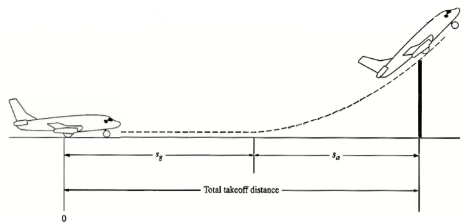
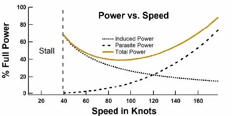
The speeds needed for takeoff are relative to the motion of the air (indicated airspeed). A headwind will reduce the ground speed needed for takeoff, as there is a greater flow of air over the wings. Typical takeoff air speeds for jetliners are in the range of 240–285 km/h (130–154 kn; 149–177 mph). Light aircraft, such as a Cessna 150, take off at around 100 km/h (54 kn; 62 mph). Ultralights have even lower takeoff speeds. For a given aircraft, the takeoff speed is usually dependent on the aircraft weight; the heavier the weight, the greater the speed needed. Some aircraft are specifically designed for short takeoff and landing (STOL), which they achieve by becoming airborne at very low speeds
Tyre Design:
When it comes to safety, tyres are one of the most important components of aircraft. They help to absorb the shock of landing and provide cushioning. It also provides the necessary traction for braking and stopping of an aircraft. An aircraft tyre is designed to withstand extremely heavy loads while landing, take off, taxing, and parking. The number of wheels required for aircraft increases with the weight of the aircraft, as the weight of the aeroplane needs to be distributed more evenly.
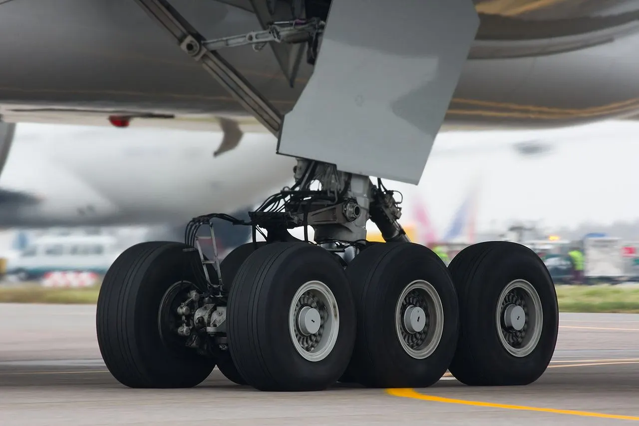
A Boeing 737NG & 737MAX uses 6 wheels, Boeing 787 uses 10 wheels, Boeing 777 uses 14 wheels and Airbus A380 uses 22 wheels. Aircraft tyres work under extreme conditions, carrying up to 340 tons and accelerating at over 250 km/hour at takeoff, in addition to enduring varied environmental stress when in flight and taxiing.
Design and Construction of Aircraft tyre:
Carcass plies are used to form the tire. They are sometimes called casing plies. An aircraft tyre is constructed for the purpose it serves.
- They support the weight of an aircraft while it is on the ground.
- It also provides the necessary traction for braking and stopping of an aeroplane.
- Tyre also helps to absorb the shock of landing and provide cushioning the roughness of takeoff, roll-out, and taxi operations.
Unlike an automobile or truck tyre, it does not have to carry a load for a long period of continuous operation. However, an aircraft tyre absorbs the high impact loads of landing, and also it’s operating at high speeds for a short time when required.
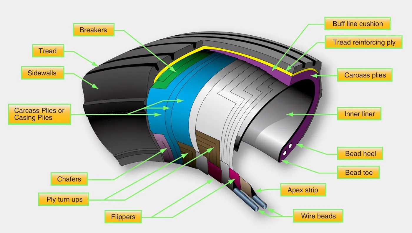
Let’s go through some technical aspects of the tyre.
Retreading – Retreading is methods of restoring a worn tyre by renewing the tread area or by renewing the tread area plus one or both sidewalls. Repairs are included in the tyre retreading process.
Load Rating – Load rating is the maximum permissible load at a specified inflation pressure.
Skid Depth – Skid depth is the distance between the tread surface and the deepest groove as measured in the mould.
Aircraft tyres must have an approved speed and load rating and have sufficient clearance when retracted through landing gear to allow for tyre growth. Tyre growth is the increase in the size of the tyre due to centrifugal forces at high speed.
Aircraft tyres may be Tube-type or Tubeless:
Tubeless tyres are more advantageous over tube-type. There is no longer the use of tube-type tyre in recent aviation. Nowadays all airliners are using tubeless tyres. Tubeless that are meant to be used without a tube has the word TUBELESS on the sidewall of the tyre.
Aircraft tyres may be Radial or Bias:
Almost all airliners are using Radial tyre. Bias is an older design, and it’s mainly used for road vehicles. Radial tyres have the word RADIAL on the sidewall. Radial tires are more expensive than bias-ply tyres. Radial tires are in demand because of their lower life cycle cost and long term value.
Are aviation tyres are conductive?
Yes, Today’s tyres are conductive. Aircraft tyres are manufactured with tread rubber with conducting compounds to permit earthing of static charges.
In early days when tyres were not sufficiently conductive, aircraft used to have a conductive strip hanging down from the axle of the landing gear. Upon landing, this strip would be the first part of the aircraft to touch the earth. This discharges any static electricity accumulated on the outer surfaces of the aircraft. Now you don’t see them anymore.
What is the purpose of Chines in aviation tyre:
Chines are also called deflectors. Chine tyre used on the nose wheel of aircraft, specially fuselage-mounted jet engines. It diverts runway water away from the engine inlets.
Chines are circumferential protrusions that are moulded into the sidewall of nose tyres that deflect water sideways to help reduce excess water ingestion into the engines. Tyres may have chines on one or both sides, depending on the number of nose tyres on the aircraft.
Aircraft Tyre Standards:
Each tyre manufacturer produces their own designs of the tyre with different tread patterns, wear patterns, wear limits etc, and in some cases, different names for the same part of the tyre. But all tyres must meet the approved standards before being accepted by the FAA or CAA. All commercial aircraft tyres approved under FAA Requirement Technical Standard Order (TSO) C62. A TSO is a minimum performance standard for specified materials, parts, and appliances used on civil aircraft.
Rolling Resistance:
Rolling resistance sometimes called rolling friction or rolling drag, is the force resisting the motion when a body (such as a ball, tire, or wheel) rolls on a surface. It is mainly caused by non-elastic effects; that is, not all the energy needed for deformation (or movement) of the wheel, roadbed, etc., is recovered when the pressure is removed. Two forms of this are hysteresis losses (see below), and permanent (plastic) deformation of the object or the surface (e.g. soil). Note that the slippage between the wheel and the surface also results in energy dissipation. Although some researchers have included this term in rolling resistance, some suggest that this dissipation term should be treated separately from rolling resistance because it is due to the applied torque to the wheel and the resultant slip between the wheel and ground, which is called slip loss or slip resistance. In addition, only the so-called slip resistance involves friction, therefore the name "rolling friction" is to an extent a misnomer.
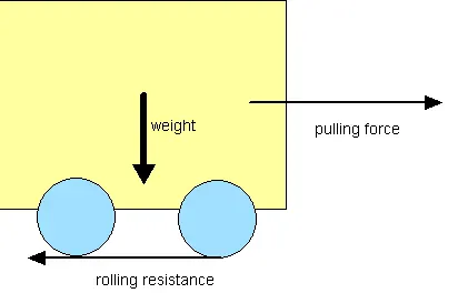
Rolling Resistance Force Frr=urr⋅m⋅g">Frr=urr⋅m⋅gFrr=urr⋅m⋅g
m = mass of the aircraft
g = gravitational consrant = 9.8 m/s^2
In analogy with sliding friction, rolling resistance is often expressed as a coefficient times the normal force. This coefficient of rolling resistance is generally much smaller than the coefficient of sliding friction.
Any coasting wheeled vehicle will gradually slow down due to rolling resistance including that of the bearings, but a train car with steel wheels running on steel rails will roll farther than a bus of the same mass with rubber tires running on tarmac. Factors that contribute to rolling resistance are the (amount of) deformation of the wheels, the deformation of the roadbed surface, and movement below the surface. Additional contributing factors include wheel diameter,load on wheel, surface adhesion, sliding, and relative micro-sliding between the surfaces of contact. The losses due to hysteresis also depend strongly on the material properties of the wheel or tire and the surface. For example, a rubber tire will have higher rolling resistance on a paved road than a steel railroad wheel on a steel rail. Also, sand on the ground will give more rolling resistance than concrete. Sole rolling resistance factor is not dependent on speed.
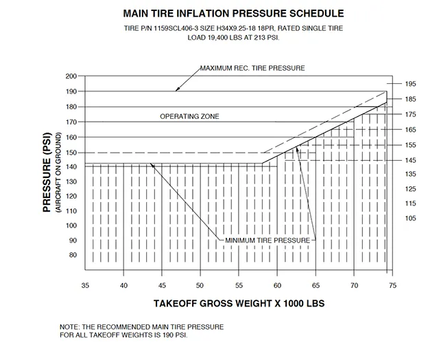
Trye Pressure:
Aircraft tires generally operate at high pressures, up to 200 psi (14 bar; 1,400 kPa) for airliners, and even higher for business jets. The main landing gear on the Concorde was typically inflated to 232 psi (16.0 bar), whilst its tail bumper gear tires were as high as 294 psi (20.3 bar).
Brakes Force:
Stopping an aircraft landing at 180-200 mph requires a lot of braking force. To do this, the aircraft has brake unit on each of the wheels on the main gear assembly. On landing, Pilots should use aerodynamic braking by applying extra back-pressure on the stick or yoke.
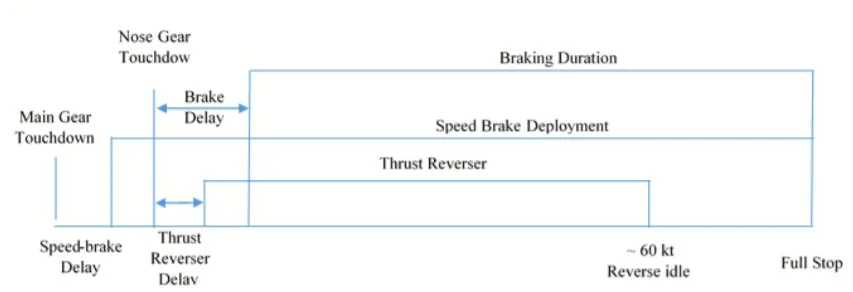
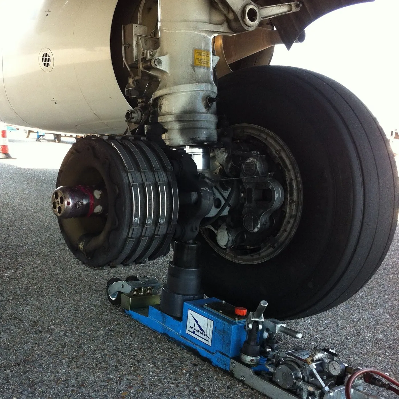
- Aircraft disc brakes in the landing gear, used to brake the wheels while touching the ground. These brakes are operated hydraulically or pneumatically. In most modern aircraft they are activated by the top section of the rudder pedals ("toe brakes"). In some older aircraft the bottom section is used instead ("heel brakes"). Levers are used in a few aircraft. Most aircraft are capable of differential braking.
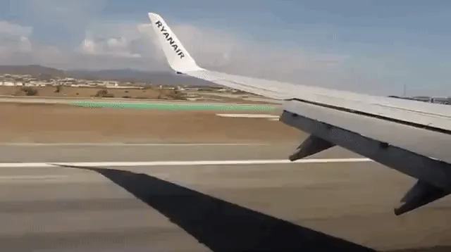
- Thrust reversers: That allow thrust from the engines to be used to slow the aircraft.

- Air brakes: It is dedicated flight control surfaces that work by increasing drag.
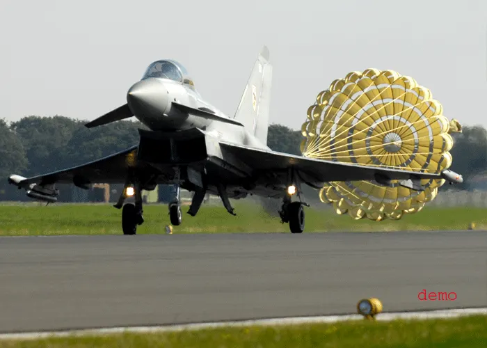
- Drogue parachutes: It is used by several former and current military and civilian aircraft (examples include the American B-52 and the soviet Tu-134 and Tu-144) and in the Space Shuttle.
Part B-
Q6)A)With necessary assumptions, calculate the force and power required to push / pull an aircraft by a towing vehicle.
Consider an Airbus A380 aircraft for this calculation,
Weight of the aircraft(including payload)=m1=575000 kg
Weight of the towing vehicle=m2=10000 kg
Coefficient of rolling resistance between aircraft tyres and runway=Crr1=0.004
Coefficient of rolling resistance between towing vehicle tyres and runway=Crr2=0.002
Drag coefficient of aircraft Cd1=0.026
Drag coefficient of towing vehicle Cd2=0.5
Air density=1.25 kg/m3
Frontal area of aircraft A1=150 m2
Frontal area of towing vehicle A2=10 m2
Velocity= 20 km/h = 5.56 m/sec
- Rolling resistance Calculation-
- For Aircraft-
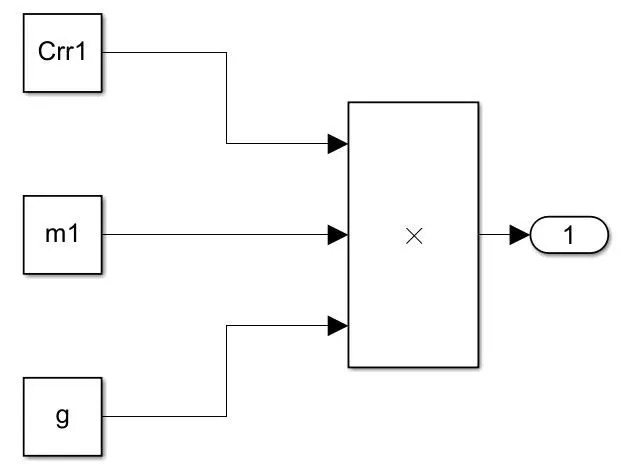
Frr1=Crr1*m1*g
= 0.004*575000*9.81
Frr1=22563 N
- For Towing vehicle-
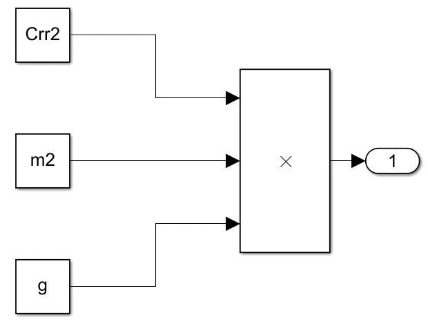
Frr2=Crr2*m2*g
= 0.002*10000*9.81
Frr2=196.2 N
Total Rolling resistance force-
Frr= Frr1 + Frr2
Frr= 22563 + 196
Frr= 22759 N
- Drag Coefficient Calculation-
- For Aircraft-
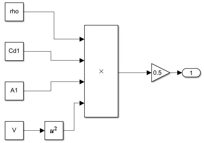
Fd1=0.5*rho*Cd1*A*V2
= 0.5*1.25*0.026*150*5.562
Fd1=75.35 N
- For Towing vehicle-
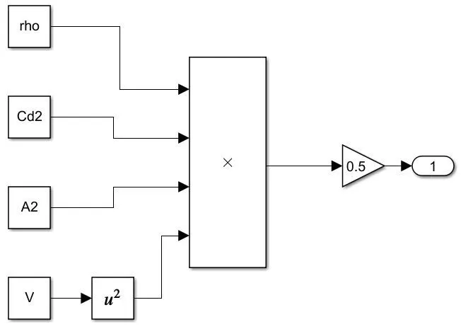
Fd2=0.5*rho*Cd2*A*V2
= 0.5*1.25*0.5*10*5.562
Fd2=96.6 N
Total Drag force-
Fd= Fd1 + Fd2
Fd= 75.35+96.6
Fd= 172 N
As aircraft is moving on plane surface hill climbing coefficient is 0
Thus total tractive force,
Fte= Frr + Fd
Fte= 22759 + 172
Fte= 22931 N
The total tractive force required to pull a fully loaded airbus A380 at 20 km/h is 22931 N
Total Tractive power,
Pte = Fte * V
Pte = 22931 * 5.56 /1000
Pte = 127.5 kW
The total tractive power required to pull a fully loaded airbus A380 at 20 km/h is 127.5 kW
B)Develop the model for the calculated force and power using Simulink.
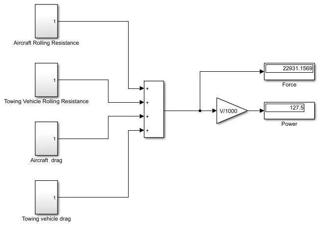
Following model shows the required model for the force and power calculation
Aircraft Rolling Resistance calculation subsystem-
Towing Vehicle Rolling Resistance calculation subsystem-
Aircraft Air Drag calculation subsystem-
Towing Vehicle Air Drag calculation subsystem-
As observed from the model output the force and power required to push the aircraft both are same as the calculated values.
Thus, calculated force and power values are verified.
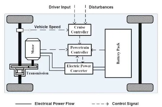
Q7)A. Design an electric powertrain with type of motor, it’s power rating, and energy requirement to fulfill aircraft towing application in Simulink. Estimate the duty cycle range to control the aircraft speed from zero to highest. Make all required assumptions. Prepare a table of assumed parameters. Draw a block diagram of powertrain.
Consider power and torque requirements from example 6(B)
The tractive force reqirement is 22.9 kN
Consider wheel radius of 25 inches i.e. 0.635 m
Torque requirement at wheels,
Tw = 22.9 *0.635
Tw = 14.5 kNm
Now, consider
Gear ratio=G=8
Gear efficiency=0.85
Motor efficiency=0.95
Thus motor torque,

Tm = 2.25 kNm
Tractive power required,

Pt = 158 kW
Now consider the towing vehicle has operation for 20 minutes
Energy Consumed=158*0.33
Energy Consumed=52.14 kWh
If battery selected is of capacity 200 kW
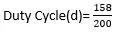
Duty Cycle(d)= 0.79
Thus duty cycle needs vary from 0% to 79% so that towing vehicle can reach its desired speed
Assumed Parameters-
| Mass of aircraft | 575000 | kg |
| Mass of the towing vehicle | 10000 | kg |
| Coefficient of Rolling Resistance 1 |
0.004 |
|
| Coefficient of Rolling Resistance 2 | 0.002 | |
| Drag Coefficient 1 | 0.0.26 | |
| Drag Coefficient 2 | 0.5 | |
| Air density | 1.125 | kg/m^3 |
| Frontal Area | 150 | m^2 |
| Velocity | 5.56 | m/s |
| Uphill gradient | 0 | deg |
| Battery Voltage | 550 | V |
Block Diagram-
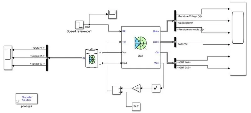
Simulink Model-
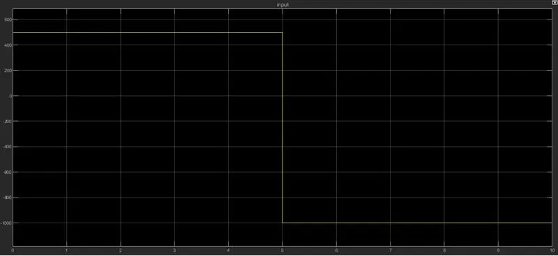
Speed Reference-
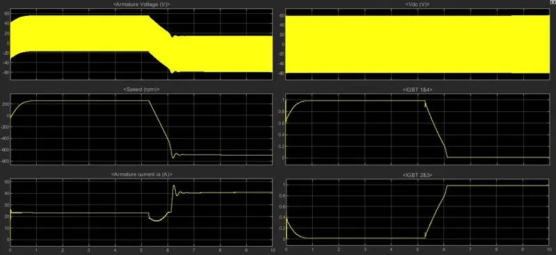
Output-
Motor-
Battery-