Week-7 Challenge: DC Motor Control
Week 7: DC Motor Control
1)
A. Explain a MATLAB demo model named ‘Speed control of a DC motor using BJT H-bridge’.
B. Comment on the armature current shoot-up from the scope results.
C. Refer to the help section of ‘The Four-Quadrant Chopper DC Drive (DC7) block’. Compare it with the H-bridge model.
Diagram of Matlab demo model named ‘Speed control of a DC motor using BJT H-bridge’ is given below-
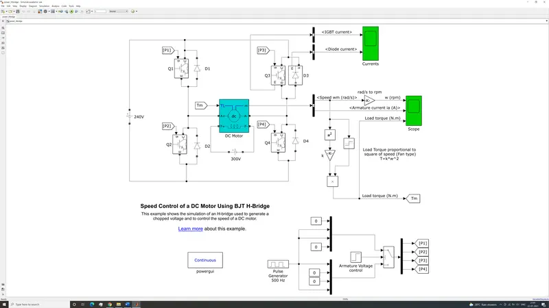
Figure 1- Speed control of a DC motor using BJT H-bridge
A DC motor consists of a field winding and armature winding. In a separately excited DC motor as shown above, the field winding is separately excited by an external source of power, in this case a steady 300 Volt supply. Speed of the motor is controlled by varying the voltage across armature winding. A fan type load (where load torque is proportional to the square of the speed in both directions) is imposed on the motor. Figure 1 depicts a circuit for speed control of DC motor using bipolar junction transistor H-bridge. This circuit varies the speed of the motor using a DC-DC chopper circuit to vary the voltage across armature winding. Circuit can also change the direction of rotation of motor by switching polarity of armature winding.
The power circuit at the top of figure 1 depicts the DC motor being supplied by a 240 Volt battery. The battery voltage and direction are controlled by four pairs of insulated gate bipolar transistors and diodes. When the motor rotates in forward direction, transistor Q1 and Q4 are conducting and diode D2 and D3 operate as free wheeling diodes. To produce torque in reverse direction, armature polarity is reversed. Transistor Q2 and Q3 are conducting and diode D1 and D4 operate as free wheeling diodes.
The armature voltage is controlled by switching the pair of transistors on and off rapidly. The gate current controlling the IGBT’s are controlled by control circuit shown at the bottom of figure. A 500 Hz pulse generator with 75% duty cycle sends signals selectively to pairs of transistor gates. The armature voltage of the motor is equal to the product of duty cycle and supply voltage (240 Volt shown here). Thus at 75% duty cycle the armature voltage is 180 Volts. This forms a chopper circuit. Thus, the pair of conducting diodes dictates the direction of motor rotation, and the duty cycle of control circuit dictates the armature voltage.
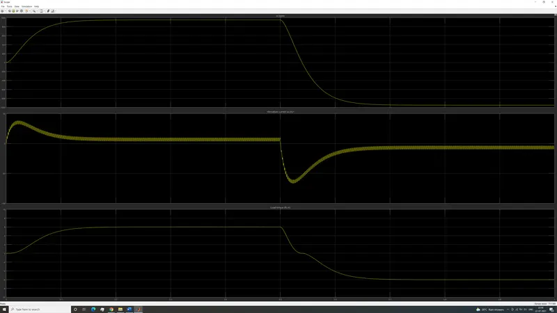
Figure 2-H-bridge Simulation Result
The graphs above plot the results of H-bridge simulation. From top to bottom, the three graphs plot armature rotational speed in rpm, armature current in amperes and load torque in newton metre over time, respectively. The simulation time is one second. The motor starts from rest and starts rotating in forward direction until achieves steady state. Then at time=0.5 seconds, polarity of armature is reversed, and motor applies torque in reverse direction.
The DC motor has characteristic high current draw at low speed as it starts from 0 rpm, trying to overcome the rotor and fan inertia. Eventually, as rotor speed increases, current decreases until motor reaches steady state of 6 Nm of load torque at 950 rpm. At time=0.5 seconds, the polarity of armature is reversed, and motor must overcome rotor and fan inertia to slow them down to 0 speed, and then back up to steady state speed in reverse direction. This again causes large initial current draw, but in negative direction. The rotor and fan eventually slow down to a stop and start rotating in reverse direction. Current starts decreasing as motor gets closer to steady state in reverse direction. Finally, the rotor and fan achieve steady state of -6 Nm of load torque at -950 rpm.
Diagram of Matlab demo model named ‘The Four-Quadrant Chopper DC Drive (DC7) block’ is shown below-
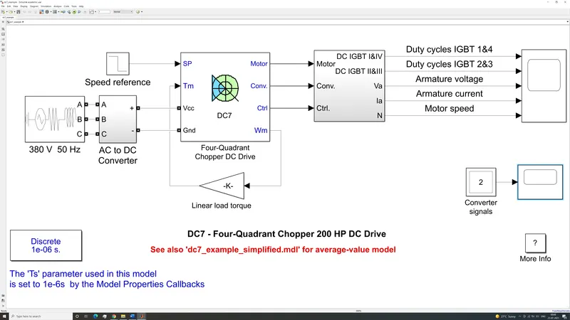
Figure 3-Four-Quadrant Chopper DC Drive (DC7) block
Figure 3 shows a diagram of 4 quadrant chopper for separately excited DC motor. The field voltage is constant at 150 Volts DC. The armature voltage is provided by an IGBT converter controlled by two PI regulators. The AC to DC converter rectifies 380 Volts AC at 50 Hz to 515 Volts DC. In order to limit bus voltage during braking, a braking chopper has been added between rectifier and DC7 block as shown below.
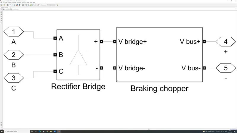
Figure 4-Braking Chopper circuit
The control block of the four-quadrant chopper is much more sophisticated than in the BJT H-bridge model. It compares speed of motor with reference speed, to calculate the torque necessary to accelerate load to target speed. In doing so, it must also compute required armature voltage and armature current. The first regulator is a speed regulator, followed by a current regulator. The speed regulator outputs the armature current reference used by the current controller to obtain the electromagnetic torque needed to reach the desired speed. The speed reference change rate follows acceleration and deceleration ramps to avoid sudden reference changes that could cause armature over-current and destabilize the system. The current regulator controls the armature current by computing the appropriate duty ratios of the 5 kHz pulses of the four IGBT devices (Pulse Width Modulation). For proper system behaviour, the instantaneous pulse values of IGBT devices 1 and 4 are opposite to those of IGBT devices 2 and 3. This generates the average armature voltage needed to obtain the desired armature current. To limit the amplitude of the current oscillations, a smoothing inductance is placed in series with the armature circuit.
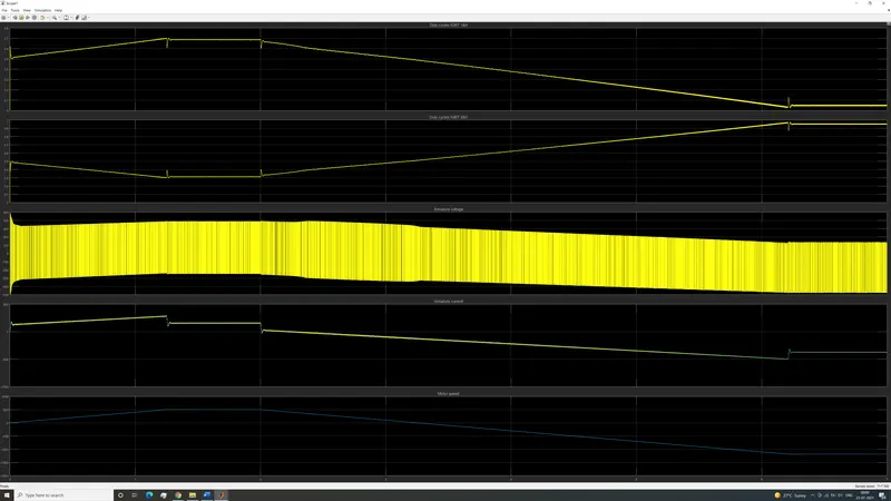
Figure 5- Four-Quadrant Chopper DC Drive Simulation output
Figure 5 shows the simulation results of given model. From top to bottom, the graphs plot Duty cycle for IGBT 1 & 4, duty cycle for IGBT 2 & 3, armature voltage, armature current and motor speed against 7 seconds of simulation time, respectively. The load torque varies linearly with speed. From the simulation results we can observe that the following happens-
The speed reference is set at 500 rpm at t=0 s. The motor speed follows the reference ramp accurately (+400 rpm/s) and reaches steady state around t=1.3 s.
The armature current follows the current reference very well, with fast response time and small ripples. The current ripple frequency is 5 kHz.
At t=2 s, speed reference drops to -1184 rpm. The current reference decreases to reduce the electromagnetic torque and causes the motor to decelerate with the help of the load torque.
At t=2.2 s, the current reverses to produce a braking electromagnetic torque (dynamic braking mode). This causes the DC bus voltage to increase.
At t=3.25 s, the motor reaches 0 rpm and the load torque reverses and becomes negative. The negative current now produces an accelerating electromagnetic torque to allow the motor to follow the negative speed ramp (-400 rpm/s). At t=6.3 s, the speed reaches -1184 rpm and stabilizes around its reference.
Not only is the 4 quadrant chopper capable of dynamic braking, it can limit charging current and has better control over armature current. The armature current depends on the difference between the reference and target values of speed and torque. This is achieved by making the duty cycle of the two pairs of IGBT’s conjugate. Unlike in the simple H-bridge model where either one pair of IGBT’s are conducting or the other depending upon the direction of rotation. Here both pairs of IGBT’s are conducting simultaneously and the difference between their duty cycles dictates the armature current and motor speed and steady state direction of rotation.
2) Develop a 2-quadrant chopper using simulink & explain the working of the same with the relevant results. (Refer to article - Multiquadrant operation of motor)
There are 2 types of 2 quadrant choppers. Type C choppers and type D choppers. Type C chopper is shown below.
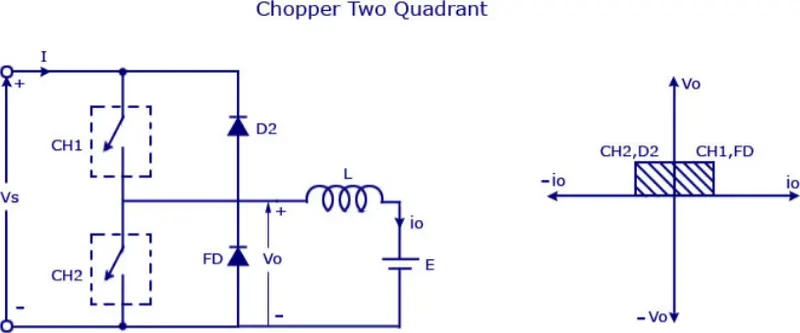
Figure 6-Type C chopper
The type C chopper works only in the positive voltage regime as can be seen from current voltage graph on the right. Current can flow in either direction depending upon which chopper is in use. The two choppers CH1 and CH2 work in conjunction with two diodes D1 and D2. When supply is turned on and CH1 is conducting, current flows through load as shown in diagram. During off cycle of CH1, motor free wheels through D1, but current flows in the same direction. When CH1 is left open and CH2 starts conducting then motor free wheels through CH2. The current flows in the opposite direction to when CH1 and D1 were in use. During the off cycle of CH2, current continues to flow in the direction opposite to what is shown in figure but instead conducts through diode D2 and charges the battery.
Type D chopper is shown below.
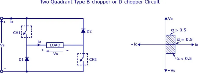
Figure 7-Type D chopper
Type D chopper works only in the positive current regime as can be seen from current voltage graph on the right. Unlike in the type C chopper, the choppers conduct in unison. When both choppers are conducting, the current flows through the load as shown in figure. When both choppers are off, the polarity of the load changes, but current flows in the same direction through both diodes.
Simulink model of type C chopper is shown below-
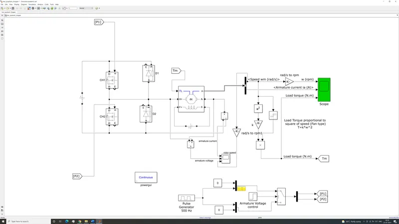
Figure 8-Simulink model of two quadrant chopper
The model contains 2 choppers and two diodes just like a two-quadrant type C chopper. The 500 Hz signal for the 2 choppers is provided by the pulse generator at the bottom. The simulation is run for 1 second. Initially the CH1 conducts current while it is on and motor free wheels through D2 during its off cycle. At t=0.5 seconds CH1 is turned off and CH2 starts conducting during its on cycle to allow the motor to free wheel. Current then passes through D1 during the off cycle of CH2. The simulation results are shown below.
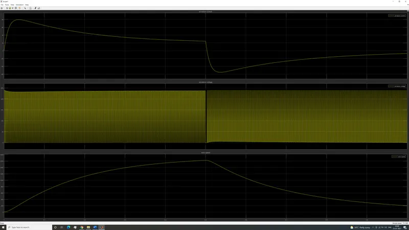
Figure 9-Two Quadrant chopper simulation output
Figure 9 shows 3 graphs. The first graph from the top plots armature current versus time. The next graph plots armature voltage vs time. The last graph plots rotor speed versus time. The rotor speeds up from standing stop until chopper 1 is turned off and chopper 2 is turned on at 0.5 seconds. The rotor starts slowing down, the current becomes negative, but the voltage remains positive. This means that regenerative braking is taking place and 2 quadrant chopper is functioning as it should.
3) Explain in a brief about operation of BLDC motor.
A brushless DC motor is an electronically commutated DC motor which does not have brushes. The controller provides pulses of current to the motor windings which control the speed and torque of the motor. The stator consists of multiple electromagnetic poles, which are energized in sequence. The polarity of each electromagnet in the stator depends upon the control electronics. The rotor consists of permanent magnets. The stator electromagnets lead the rotor magnets and switch polarity before the rotor catches up. The following sequence of images shows a BLDC motor in various positions of rotor throughout a rotation.
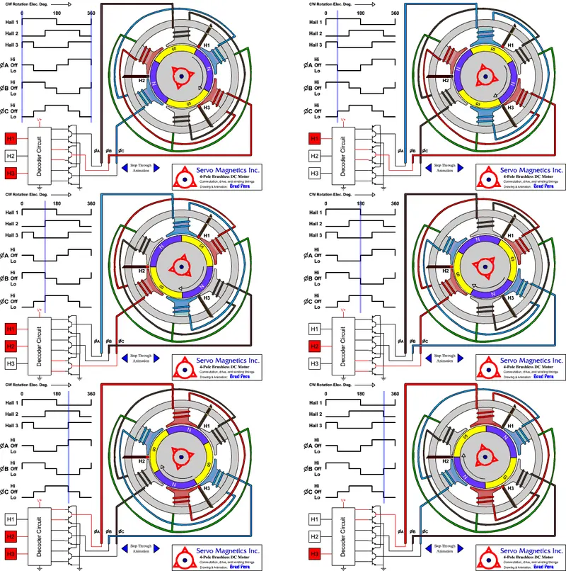
Figure 10-Brushless DC motor
Figure 10 depicts a 4 pole BLDC motor with 6 stator poles rotating in clockwise direction. Opposing stator poles are energized in pairs. This means that only two out of three phases are conducting at any given time. As we can see the three phases are controlled by the decoder circuit, which rely on 3 hall sensors to determine rotor position. Polarities of pole pairs change every 60 degrees. The stator electromagnets generate their own magnetic field. One pair repelling the nearest like pair of rotor poles and the other attracting the nearest unlike pair of rotor poles. The vector sum of the magnetic fields generated by stator poles lead the rotor magnetic field to create torque.
The phases in figure 10 are labelled A, B and C. The polarity of each phase can be seen at the top left of each diagram, indicated by the purple line. The hall effect sensor output is also shown in the same way. The phase signal and hall effect sensor output are plotted over 360 degrees of rotation. Here we can clearly see that only two phases are conducting at any point during the rotation. From the perspective of an individual stator pole, it oscillates between magnetic north and south depending upon direction of current passing through the coil around it. For 120 degrees of rotor angle, current flows in one direction, then 60 degrees of no current, then 120 degrees of current flowing in opposite direction followed by another 60 degrees of no current. After this the cycle repeats for every rotation of rotor. The waveform of current through each phase is the same for all stator poles, just offset by 120 degrees to each other.
The example shown above uses trapezoidal waveform, but this is not necessary for its function. Even though it is called a DC motor, it can run on AC current. When connected directly to AC mains, without decoder circuit, it acts as a synchronous motor at line frequency of 50 or 60 Hz. When used this way, it is known as permanent magnet synchronous motor. PMSM can be used for automotive applications using a variable frequency drive to vary synchronous speed.
BLDC motors produce high torque for their size and do not have sparking and noise issues associated with brushed DC motors. They are very efficient and have high peak efficiency. Average efficiency suffers slightly due to low-speed current draw and high-speed hysteresis losses. Despite this, BLDC motors require less rotor cooling than induction motors of the same power output. This makes them ideally suited for applications requiring high torque density and high efficiency and long life.