Week - 4
Stateflow of Washing Machine and Gearbox
AIM:
1) Implement control logic of washing machine using stateflow.
2) Make Simulink chart for “Gear Shift” logic.
OBJECTIVE:
For Washing Machine-
1) If power supply or water supply is not available, stop the process and indicate through LED.
2) Soaking time should be 200s, washing time 100s, rinsing 20s and dryer for 50s.
3) Turn on LED to indicate process is finished.
For Gearbox-
1) Change the gear according to following criteria-
|
Speed Range (kmph) |
Gear |
|
0 to 15 |
1 |
|
16 to 25 |
2 |
|
26 to 40 |
3 |
|
41 to 60 |
4 |
|
Above 61 |
5 |
Body of Work:
1) Washing Machine
Image 1 shows the Simulink block diagram for washing machine logic.
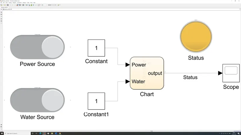
Figure 1-Washing Machine Control Logic
It consists of two toggle switches which control whether the washing machine receives power and water. The two constants indicate “1” if supply is available and “0” if supply is not available. These two constants are used as inputs for a chart. The chart gives an output which indicates the status of the washing machine. The value of status is stored in a scope block and is also indicated by a lamp block. The chart logic is shown below.
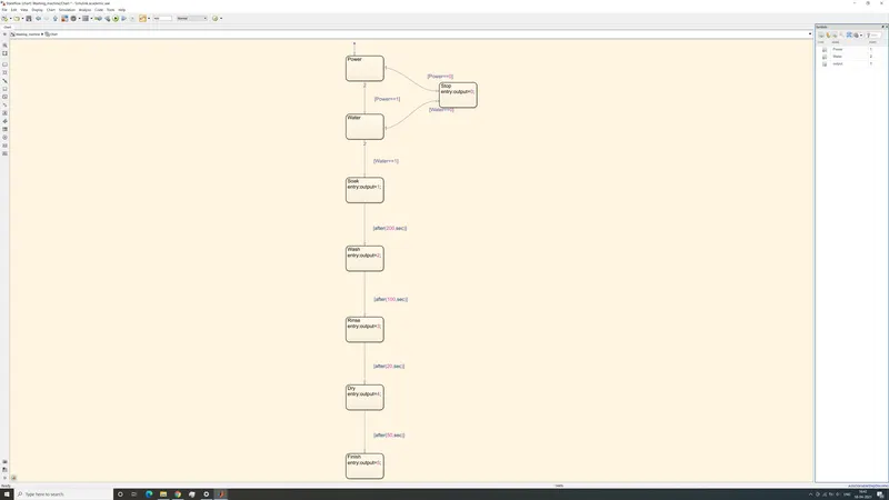
Figure 2-Washing machine stateflow diagram
The two inputs are used to determine the status of the washing machine as variable “output”. There are 6 unique values of output ranging from 0 to 5. If either power supply or water supply are not present, then the washing machine does not start, and output is 0. In this case the lamp turns red in color. The next 4 values of output depend on which step of the washing process the machine is currently engaged in. The four steps being soaking, washing, rinsing, and drying, respectively. The 4 states are separated by time delays as stated earlier. Regardless of which of these 4 states the washing machine is currently in, the lamp will glow an amber color. Once, all other processes are complete, the value of output becomes 5. The lamp glows green and indicates the washing process is complete.
2) Gearbox
Figure 3 shows the Simulink block diagram for gearbox shift logic.
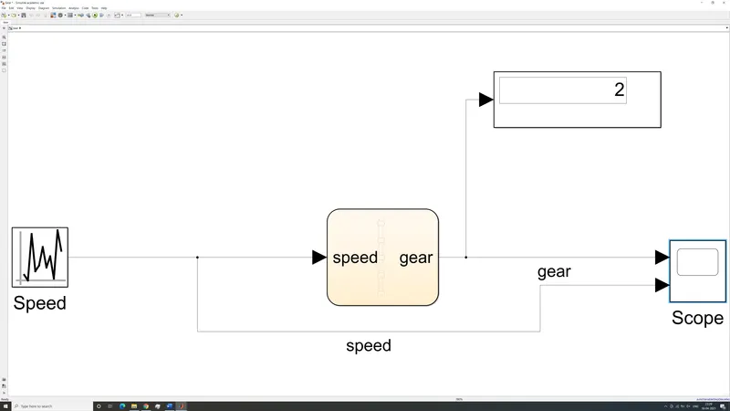
Figure 3-Gearbox Shift Logic Block Diagram
It consists of a uniform random number generator which outputs numbers between 0 and 80. This is used as an input for the chart as speed. For the gear to change according to the parameters shown earlier, we must create a stateflow logic using the chart to change the gear according to the speed. The output of the chart is the gear the car needs to be in according to the speed. The gear the car is currently in is displayed by a display block and the gear shifts are logged by a scope block over the course of the simulation. The scope also uses the uniform random number generator as an input to compare the speed and gear number. The chart logic is shown below.
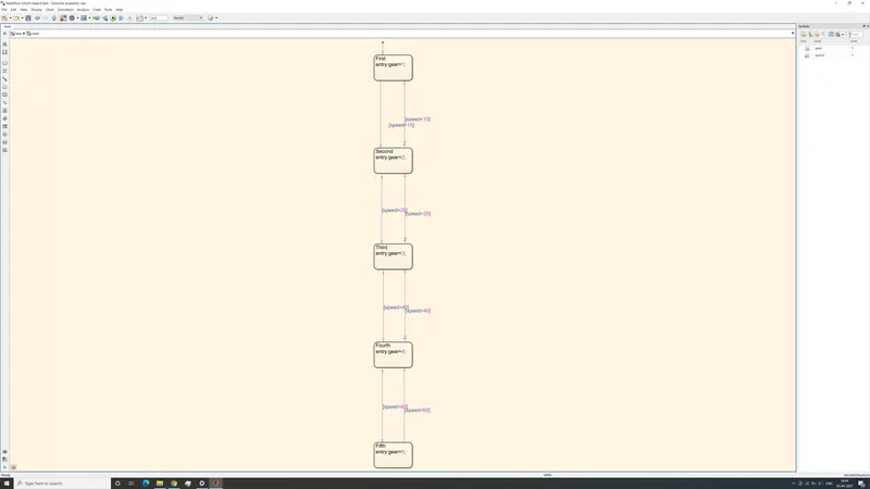
Figure 4-Gearbox stateflow diagram
The value of output variable “gear” changes based on the input speed. As the car speeds up, the value of gear selected increases and vice versa. All gears are forward gears and there are 5 gear ratios to choose from depending upon the speed.
CONCLUSION:
1) Washing Machine
When Power supply and water supply are available the washing machine goes through all 4 cycles and eventually indicates completion with a green light.
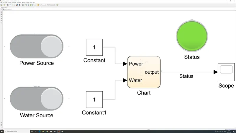
Figure 5-Power and Water supply allows washing process to continue to completion indicated by green lamp
The value of output as logged by scope is shown below.
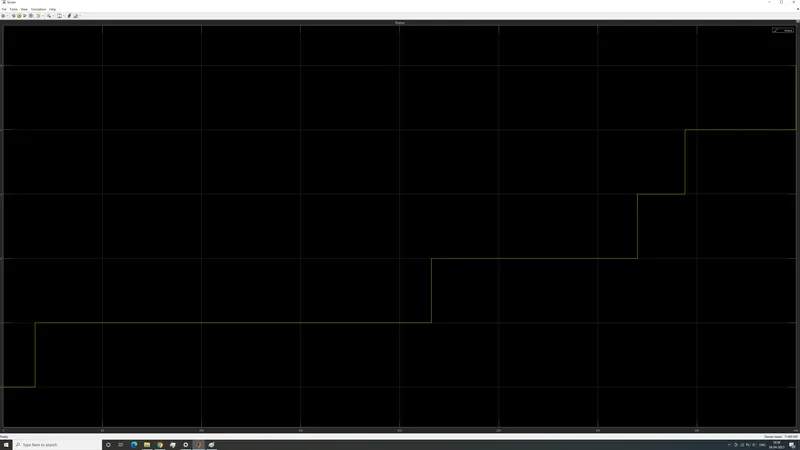
Figure 6-Value of status from scope block
The scope clearly shows that the value of output increases monotonously in a stepwise manner over the 400 seconds of simulation time. The first 30 seconds indicate an output of “0”. The next 200s have an output value of “1”. This indicates soaking. Washing consumes another 100s during which output value is “2”. The next 20s indicates rinsing process and has a value of “3”. The output value “4” lasts for 50s indicating drying process. Finally the output increases to value “5” at the end of the 400s run, indicating completion of washing cycle.
When power supply, water supply or both are turned off, the washing process stops and is indicated by a red lamp.
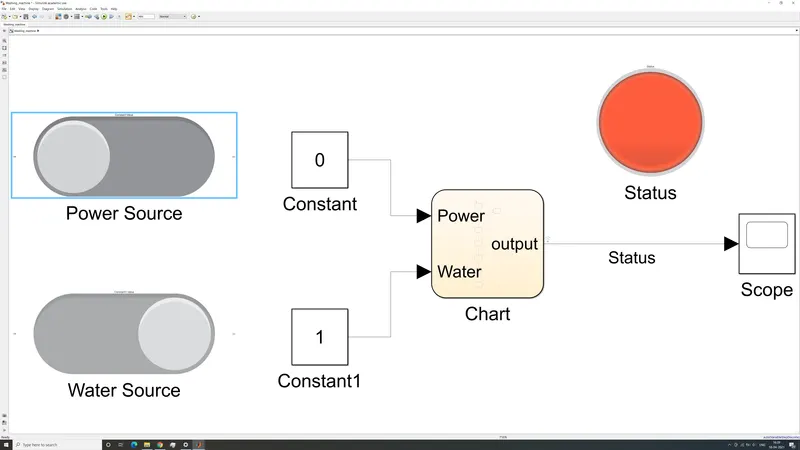
Figure 7-Turning the power supply off stops the process and is indicated by a red lamp
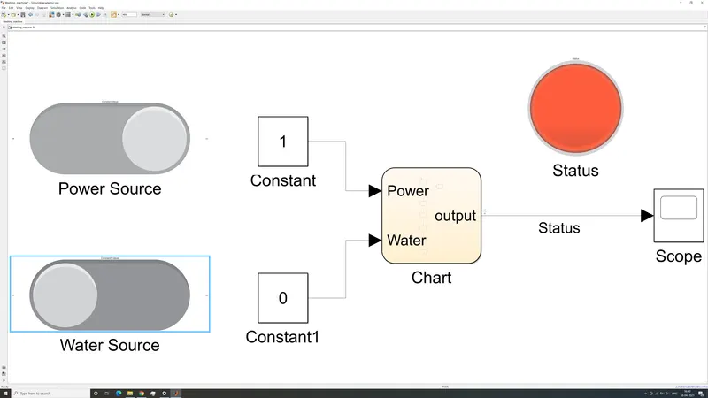
Figure 8-Turning the water supply off stops the process and is indicated by a red lamp
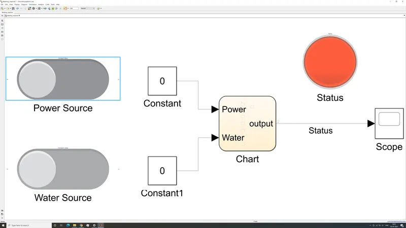
Figure 9-Turning off both the power and water supply stops the process and is indicated by a red lamp
In any case in which power supply water supply or both are turned off, the value of output remains “0”.
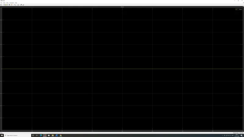
Figure 10-Turning off water supply, power supply or both causes an output of “0” indicated by a red lamp
2) Gearbox
As can be seen from figure 11 the gearbox changes gear according to the speed of the car.
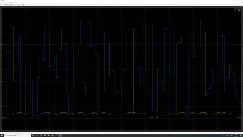
Figure 11-Speed and gear number