Kinematics of 2R Robotic Arm
2R Robotic Arm Challenge
AIM: Write a program in Matlab to simulate the forward kinematics of a 2R Robotic Arm.
OBJECTIVE: Create an animation file of the plot.
BODY OF CONTENT: Program is written in Matlab and is attached below-
% Forward kinematics of a 2R robotic arm manipulator
clear all
close all
clc

%Inputs
l1=1;
l2=0.5;
theta1=linspace(0,180,10);
theta2=linspace(0,180,10);
ct=1;

for i=1:length(theta1)
    THETA1=theta1(i);
    for j=1:length(theta2)
        THETA2=theta2(j);
        %Coordinates
        %Base of robot arm
        x0=0;
        y0=0;
        %End of link 1
        x1=l1*cosd(THETA1);
        y1=l1*sind(THETA1);
        %End of link 2
        x2=x1+l2*cosd(THETA2);
        y2=y1+l2*sind(THETA2);
        %plotting
        plot([x0 x1],[y0 y1],[x1 x2],[y1 y2],'linewidth',3)
        axis([-1.5 1.5 0 1.5])
        M(ct)=getframe(gcf);
        ct=ct+1;
    end
end

movie(M)
videofile=VideoWriter('robot_kinematics.avi','Uncompressed AVI');
open(videofile)
writeVideo(videofile,M)
close(videofile)
The program simulates the kinematics of a 2R robotic arm with 2 rotary joints and 2 linkages of different lengths. The first link has one end at origin and the other is free to rotate about the origin at any angle between 0 and 180 degrees. The second link has one joint common with the free end of the first link and the other end is free to rotate about this common joint. The end effector/manipulator is connected to the free end of the second link. The second link can also form an angle with the horizontal axis varying from 0 to 180 degrees, independent of the first link.
The program starts by clearing the workspace, command window and removing all plots. Next, the length of each link is specified by the user and remains constant throughout the program. Following this, two arrays are generated specifying the respective angles at which the 2 links are inclined to the horizontal axis. A counter variable (ct) is initialized and assigned a value of 1. This variable will be used count the number of frames in the video later in the program. This completes all the inputs necessary for the remainder of the program.
As we want the second link to sweep through its entire range of motion for every angle of the first link, two for loops need to be written one inside the other. This allows us to increment the values of theta2 while keeping theta1 constant throughout a loop. The outer loop increments over the values of theta1 and the inner loop increments the values of theta2. For every loop, the current value of theta1 and theta2 are stored in variables THETA1 and THETA2. THETA1 and THETA2 are used to calculate the coordinates of the end of both links using simple trigonometry. The coordinates calculated are x1, y1, x2 and y2 as x0 and y0 are already given. The following formulae are used to calculate these coordinates
x1=l1*cos(THETA1)
y1=l1*sin(THETA1)
x2=x1+l2*cos(THETA2)
y2=y1+l2*sin(THETA2)
Now that the coordinates of the end of each link is known within a given loop, it is plotted using the plot command. The axes are fixed based on the maximum extent of the end effector. Then each plot is saved in an array called M using the getframe command. The counter variable ct is then incremented.
Once both loops end, the plots in array M are used as frames of an uncompressed avi video named robot_kinematics.avi. The file must be named, opened, written to using array M, and then closed. This allows the individual plots to be saved as a video outside the matlab program.
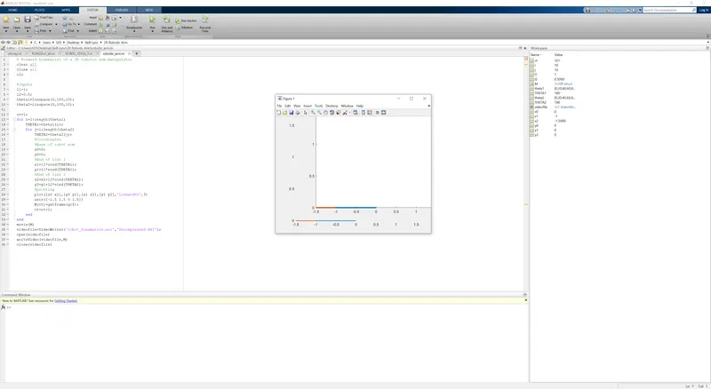
Figure 1-Program Output
Shown above is the matlab program running. In the middle is the last frame of the animation in which both the links have completed their entire range of motion from 0 to 180 degrees to the horizontal axis. Since both theta1 and theta2 contain 10 elements, M will have 100 plots. This is also indicated by the fact that ct is 101, as it was originally assigned a value of 1, it has incremented 100 times.
CONCLUSION:
Video file of 2R robot kinematics has been generated and uploaded to youtube. To access the video follow the given link https://youtu.be/VsFTVdW1XVc
Link for report on projects page is https://skill-lync.com/projects/kinematics-of-2r-robotic-arm-2
One possible improvement could be made to the extent of the axes. They could be programmed to change with the linkage lengths automatically rather than rely on user input.