Week-6 Challenge: EV Drivetrain
Week 6: EV Drivetrain
1) Which types of power converter circuits are employed in electric and hybrid electric vehicle?
AC to DC converter (Rectifier)-Used for charging battery by plugging into AC wall socket.
DC to AC converter (Inverter)-Used as AC motor drive for supplying AC voltage to induction motor from battery.
DC to DC converter (chopper)-Used for stepping down voltage from battery terminal voltage to any value less than terminal voltage. Necessary as DC motor drive to control speed of DC motor, or to run other low voltage accessories.
AC to AC converter-Used for changing voltage or frequency of AC waveform. Implemented in ceiling fan regulator and variable frequency drive for speed control of induction motor (usually integrated into inverter).
2) An Electric Vehicle's powertrain with 72V battery pack in shown in the diagram below. The duty ratio for acceleration operation is 'd1' and for the braking operation the duty ratio is 'd2'.
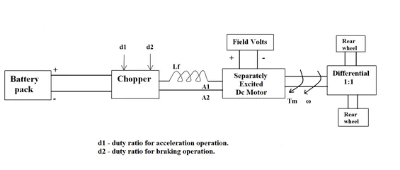
The other parameters of the electric vehicle is given below,
Motor and Controller Parameters:
Rated Armature voltage= 72 V
Rated armature current= 400 A
Ra= 0.5Ω, KΦ= 0.7 Volt second
Chopper Switching frequency= 400 Hz
The vehicle speed-torque characteristics are given by the below equation
What is EV steady state speed if duty cycle is 70%?
From torque speed relation for DC motor we have-
T*Ra= (KΦ*d1*Voltage)-(KΦ2*ω)
On substituting values we get-
T(0.5)=(0.7*0.7*72)-(0.72*ω)
T/2=35.28-0.49ω
T=70.56-0.98ω
Equating above equation with given vehicle speed-torque characteristic equation we get-
24.7+0.0051ω2=70.56-0.98ω
0.0051ω2+0.98ω-45.86=0
On solving above quadratic equation and ignoring negative solution we get ω=38.9 rad/s=371.6 rpm.
3) Develop a mathematical model of a DC Motor for the below equation using Simulink.
ω=(V/Kϕ)–(Ra.T)/Kϕ2
Simulink model for equation is shown below
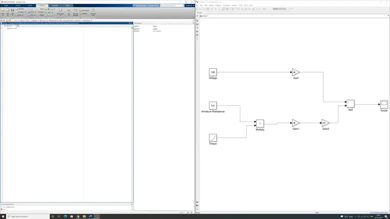
Figure 1-Simulink model of formula
The model depicts voltage and armature resistance as constant inputs. The last input, torque, is input using ramp. Torque increases by 1 unit per second in this simulation to calculate different values of speed over a range of values of torque from 0 to 100 units. The value of voltage is divided by the value of motor constant. The value of torque is multiplied by armature resistance before being divided by the value of motor constant twice. The final difference between these two values gives us the value of omega which is displayed in scope. Scope output is shown below.
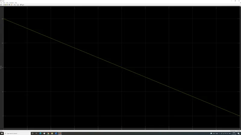
Figure 2-Scope output
In figure 2, rotor speed is plotted on vertical axis. Time is plotted on horizontal axis, but since the increase in torque is numerically equal to the passage of time, the above graph can be considered a motor speed vs torque graph. As expected of a DC motor, the speed reduces with increasing torque at constant voltage.
4) Refer to the blog on below topic:
Induction Versus DC brushless motors by Wally Rippel, Tesla
Explain in brief about author’s perspective.
The author compares induction and DC brushless motors, their construction, advantages, disadvantages, history, and applications. The construction of the stators of both machines is nearly identical, the rotor construction and control are what differentiate the two. The induction motor has armature windings into which current is induced by a difference in speed between rotor speed and field rotational speed. No magnets are used in the construction of induction motor rotor. The DC brushless motor on the other hand contains permanent magnets in its rotor and relies on the switching polarities of stator cores to alternately attract and repel rotor magnets to provide constant torque. This gives the two motors their unique properties and drive requirements.
The AC induction motor was invented in 1889, long before sophisticated motor drives were available. Despite this, the induction motor could function as a synchronous device when supplied by utility 3 phase electricity from a wall socket. For use in modern electric vehicles, a speed sensor is required to control the slip speed of motor and an inverter to vary the field frequency. The DC motor on the other hand requires an inverter to function. Hall effect sensors are used to detect rotor position and change polarity of stator poles.
Induction motors also have much higher rotor cooling requirements than a DC motor of the same power output. The limitation of permanent magnet motors is the part load efficiency loss and low speed current draw. The high starting current required to produce good starting torque causes high copper losses at low speeds. At part throttle the eddy and hysteresis losses caused by the rotating magnets causes efficiency to drop. This effect increases with increasing motor size. Induction motors on the other hand have no permanent magnets and can adjust their rotor field strength by reducing voltage and minimize magnetic losses. This means that DC motors have an advantage in peak efficiency, but induction motors have higher average efficiency.
Finally, permanent magnets are expensive, but induction motors are more difficult to control and lead to higher development costs. The author believes that DC brushless motors are ideally suited for hybrids which prioritize torque density and induction motors are best suited for high performance purely electric cars.