Week-6 Challenge: EV Drivetrain
1.Which types of power converter circuits are employed in electric and hybrid electric vehicle?
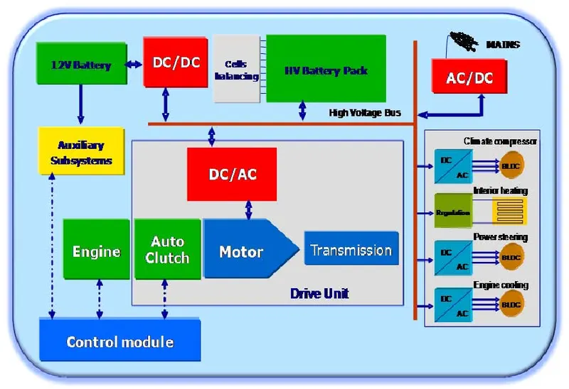
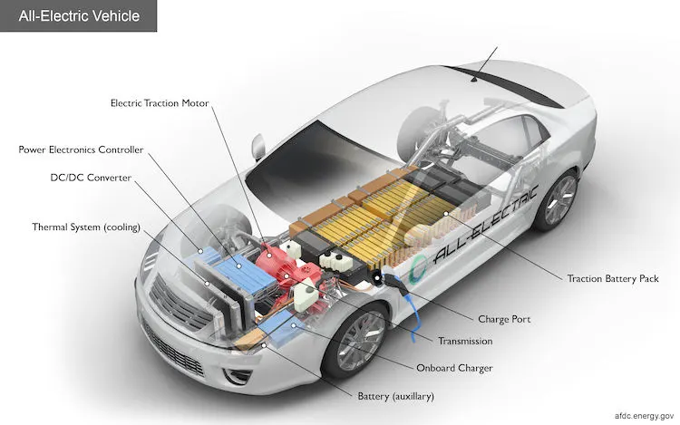
There are four main types of converters are used in EVs and HEVs.They are:
- AC to DC converters
It is also known as Rectifiers.They convert DC signal into AC supply.We use these converters in mobile chargers,laptop chargers etc. Basically these circuits are made up of stepdown transformers,diode,resistors,capacitors for filtering,voltage regulators etc. In EVs or HEVs application the battery inside the vehicle is DC and we are charging it with AC supply through on board charger or off board chargers and for this we need this AC to DC power converters.
- DC to AC converters
These circuits are known as inverters.these converts DC voltage into AC voltage.There are different types of inverters: Single phase,Three phase invertors,voltage source inverters,current source inverters,series inverters,parallel inverters,bridge type inverters,etc.In EV application there is 3phase induction motor and inorder to power that Ac supply is required so for that these inverters are needed.
- DC to DC converters
These are also known as choppers .These converters are used to convert the voltage levels of DC signals.There are mainly two types of DC-DC converters:
- Isolated type :
- Buck converter - to step down the voltage
- Boost converter - to step up the voltage
- Buck Boost converter - can do both step up and step down the voltage levels.It is used in reverse polarity conditions
- Charge pump - to step up or step down the voltage levels for low power devices
- Cuk converter - step up/down converter with zero ripple current
2.Non isolated type :
- Forward converter
- Flyback converter
In Ev applications the wiper motor,radio or any other infotainment systems or small dc devices not require the battery voltage so inorder to step down the voltage we should use buck converters.
- AC to AC converters
A solid-state ac to ac converts an AC waveform to another AC waveform, where the output voltage and frequency can be set arbitrarily.
Types:
- Cycloconverters
A cycloconverter constructs an output, variable-frequency, approximately sinusoid waveform by switching segments of the input waveform to the output; there is no intermediate DC link. With switching elements such as SCRs, the output frequency must be lower than the input. Very large cycloconverters (on the order of 10 MW) are manufactured for compressor and wind-tunnel drives, or for variable- speed applications such as wind mills,cement kilns.
- DC link converters:
First the AC is converted into DC by rectifier and it removes the negative portions and output only the positive part.
- matrix converters
In order to achieve higher power density and reliability, it makes sense to consider Matrix Converters that achieve three-phase AC-AC conversion without any intermediate energy storage element
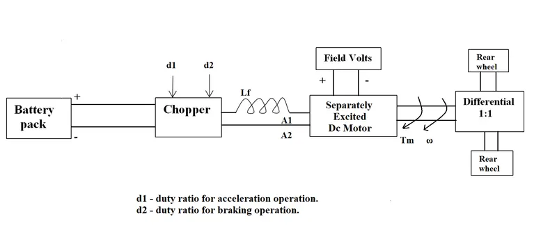
2. An Electric Vehicle's powertrain with 72V battery pack in shown in the diagram below. The duty ratio for acceleration operation is 'd1' and for the braking operation the duty ratio is 'd2'.
The other parameters of the electric vehicle is given below,
Motor and Controller Parameters:
Rated Armature voltage= 72 V
Rated armature current= 400 A
Ra= 0.5Ω, KΦ= 0.7 Volt second
Chopper Switching frequency= 400 Hz
The vehicle speed-torque characteristics are given by the below equation

What is EV steady state speed if duty cycle is 70%?
For 70% duty cycle,rated armature voltage ,V = (70/100)*72 = 50.4V
Torque equation of motor, ω = V/Kϕ -(Ra/Kϕ^2)T
rearranging for Tm , Tm = (-ω + V/Kϕ) ((Kϕ)^2/Ra)
Here vehicles torque is given as ,
equating both torques and solving we get a quadratic equation:
putting values of V, Kϕ, Ra,T :
0.0051ω² + 0.98ω - 45.86 = 0
this is a quadratic equation of type: ax² + bx + c =0
and can be solved using the formula :
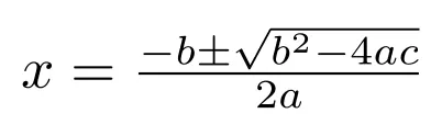
solving for angular velocity,ω we get
ω = 38.91 rad/s or -231.07 rad/s
neglect -ve value
put ω = 38.91 rad/s in Tv equation
Tv = 24.7 + (0.0051*38.91*38.91)
= 32.42 Nm
EV steady state speed = 38.91rad/s
3. Develop a mathematical model of a DC Motor for the below equation using Simulink.
ω = V/Kϕ -(Ra/Kϕ^2)T
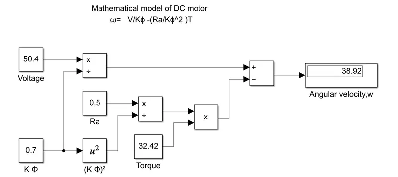
The simulink mathematical model for DC motor having below parameters are designed successfully and the output obtained is verified.
- Voltage,V = 50.4
- Kϕ = 0.7
- Armature of resistance ,Ra = 0.5Ω
- Torque,T= 32.42Nm
constant blocks are used for giving the values of V, Kϕ,Ra,T
for squaring math function block is used and the result is displayed in display block.
4.Refer to the blog on below topic:
Induction Versus DC brushless motors by Wally Rippel, Tesla
Explain in brief about author’s perspective.
- In older days we had lead acid battery,Dc brushed motor,contact controllers now it is replaced by Lithium ion battery,Dc brushless motor or Induction motor and modulating inverter drives.
- Auther is describing the difference between the DC brushless motor and Induction motor and which has the best performance
DC brushless motor has:
- Rotor contains 2 or more permanent magnets
- stator core is made up of thin stacked laminations.
- As the rotor rotates the magnitude and polarity is continously varied
- Inverter provides current control
- Stator of both BLDC motor and 3phase induction motor are same.Both have three sets of distributed windings in stator core but rotors are different.
- Rotors of Induction motor has no magnets.It has stacked steel laminations and conductors that form shorted structure
- Stator winding produce rotating magnetic field
- Both have similar stators and drives uses 3phase modulating inverters
- difference is rotors and inverter controls
- Digital controllers - control differences are with the control code
frequency of rotating magnetic field = applied electrical frequency - rotating frequency of rotor
Induced voltage at shorted structure ∝ speed difference between rotor and electrical frequency ∝ motor current
thus produced current interact with original magnetic field to produce torque
- When maximum toque is required at low speed magnetic field strength ,B should be maximum.So that the inverter and motor current maintained at lowest possible values also this reduces the I²R losses so increase in efficiency
- When low torque is required B should be decrease such that Eddy current and hysterisis loss is minimized
|
DC brushless motor |
Induction motor |
|
|