Week-7 Challenge: DC Motor Control
1. A. Explain a MATLAB demo model named ‘Speed control of a DC motor using BJT H-bridge’.
The simulink model is shown below:
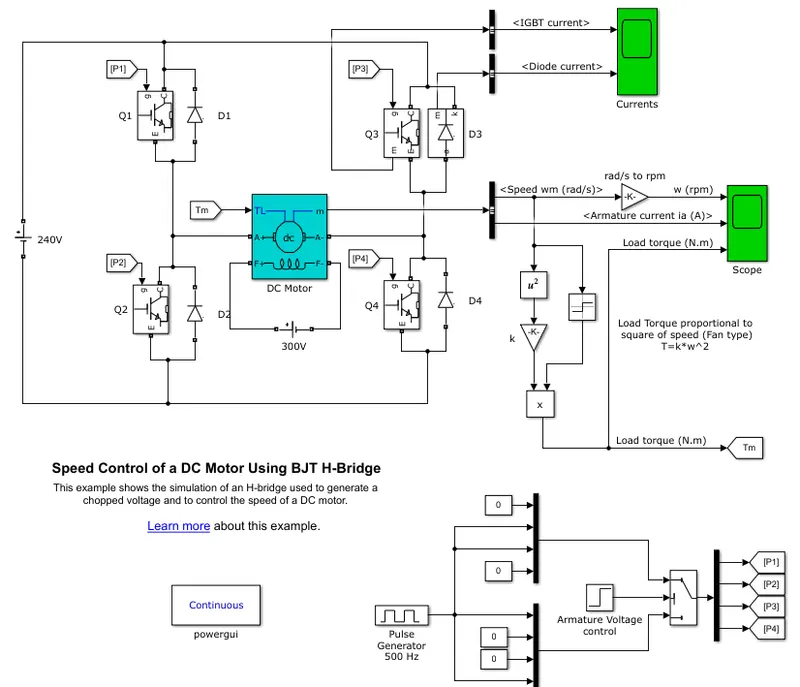
The speed control of a dc motor using BJT H-bridge is implemented using simulink.This example shows the simulation of an H-bridge used to generate a chopped voltage and to control the speed of a DC motor.The Bipolar Junction Transistor (BJT) when used for power switching applications, operates as an IGBT. When it is conducting (BJT operating in the saturated region), a forward voltage Vf is developed between collector and emitter (in the range of 1 V). Therefore, the IGBT block can be used to model the BJT device.
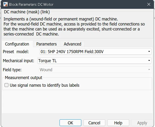
The IGBT block does not simulate the gate current controlling the BJT or IGBT. The switch is controlled by a Simulink® signal (1/0). The DC motor uses the preset model (5 HP 24V 1750 rpm). It simulates a fan type load (where Load torque is proportional to square of speed). The armature mean voltage can be varied from 0 to 240 V when the duty cycle (specified in the Pulse Generator block) is varied from 0 to 100%.
The H-bridge consists of four BJT/Diode pairs (BJT simulated by IGBT models). Two transistors are switched simultaneously: Q1 and Q4 or Q2 and Q3. When Q1 and Q4 are fired, a positive voltage is applied to the motor and diodes D2-D3 operate as free-wheeling diodes when Q1 and Q4 are switched off. When Q2 and Q3 are fired, a negative voltage is applied to the motor and diodes D1-D4 operate as free-wheeling diodes when Q2 and Q3 are switched off
While running simulation:
The motor starts in the positive direction with a duty cycle of 75% (mean DC voltage of 180V). At t= 0.5 sec., the armature voltage is suddenly reversed and the motor runs in the negative direction.'Scope' shows motor speed, armature current and load torque and 'Currents' shows currents flowing in BJT Q3 and diode D3.
The basic diagram of speed control of a DC motor using Bipolar Junction Transistor(BJT) H-bridge is shown:
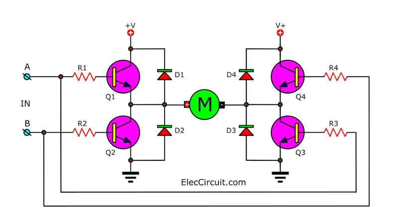
The input voltage here applied is 240V dc supply.Here the BJTs are connected in a "H" like configuration so the name H-bridge.The circuit consists of Transistors,diodes,resistors,and motor in the centre whose speed is to be controlled.Across transistors diodes are connected parallel.
DC motor:
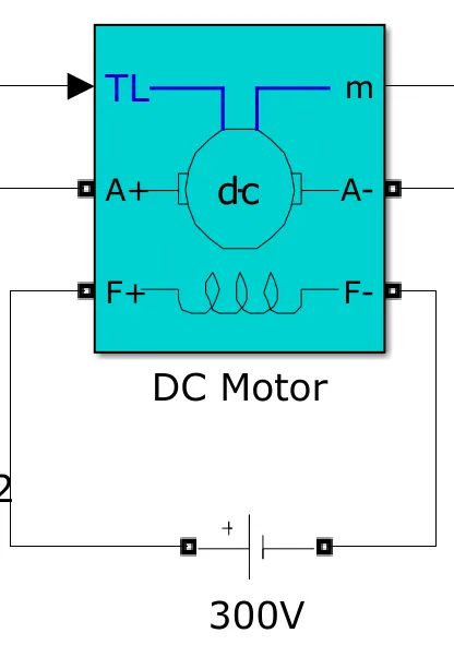
This is a seperately excited DC motor.The stator field windings must given a voltage.Here the field is given a voltage of 300V.The motor parameters are shown below:
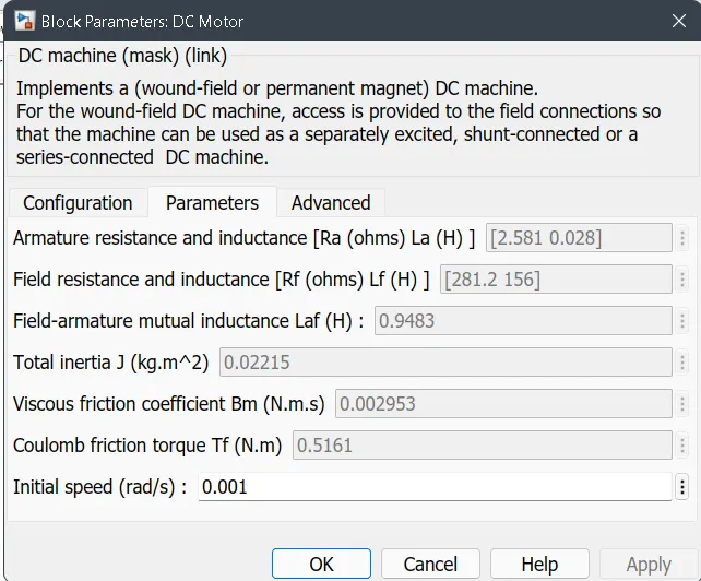
Tl is the load torque input it is given to the motor shaft ,and it is closed loop system the rotational speed output in rad/s from motor is converted into Torque by using the equation T = k*w^2 .The speed in rad/s is squared using math function block and it is multiplied with a gain and its result is multiplied with a signum function which gives output 1 for +ve ,0 for zero value and -1 for negative values.And this calculated torque is given back to the Load torque.The load torque output is shown below:
The armature of the motor is connected as shown below between H bridge.And the armature current waveform is shown below:
The speed output in rad/s is also shown:
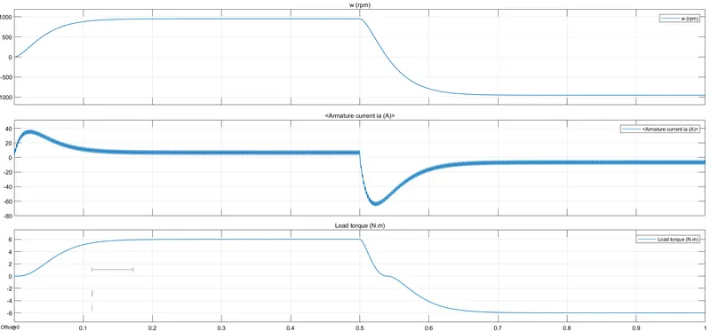
Here we can see that the speed is gradually increasing and remains in 950rad/s and then exponentially decreasing and remains negative.
Armature current increases first then remains 0 then decreases to -ve value and remains zero.
Torque increases and then remains in 5.8Nm for 0.5s and suddenly drops to -5.8Nm
The Bipolar Junction Transistor is shown below:
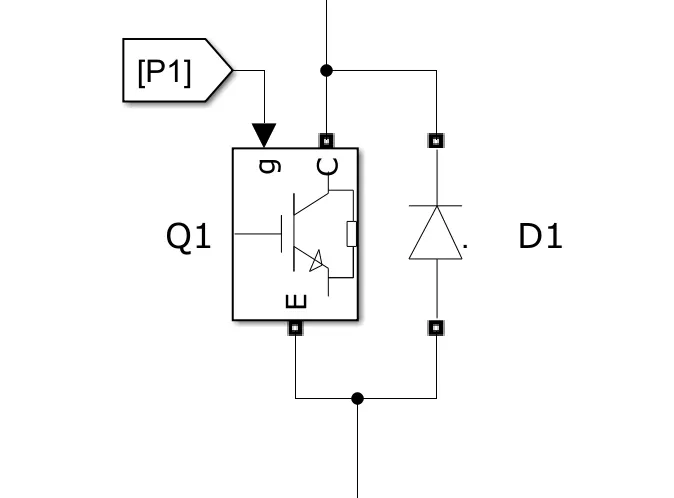
It has three terminals Emitter,collector,base.In base we have to apply gate pulses from pulse generator.The BJT is basically a switching device .When power electronics application we use IGBT that is Insulated Gate Bipolar Transistor is used .And when the gate pulse is given the switch gets closed.When the pulse is zero switch is opened.the parameters are given:
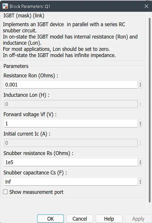
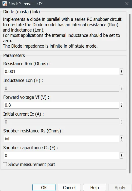
Across this a diode is connected having the following parameters.
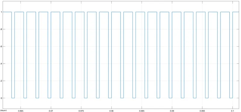
The pulses are generated using the pulse generator.The pulses having 500KHz frquency is applied.The pulse given to the gate of IGBT is shown below:
These pulses are generated using the following circuit:
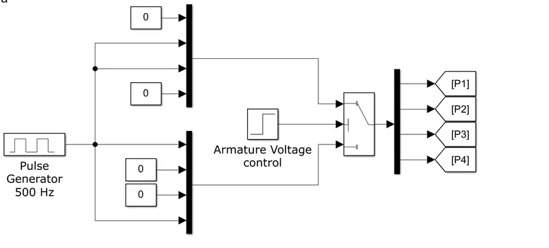
The pulse generator output is multiplexed with 2 zero constant blocks and each multiplexer output is given to a switch which is controlled by armature voltage control .It is acheived by step input signals.The threshold value is 0.5V.And it is given to gate of IGBT.
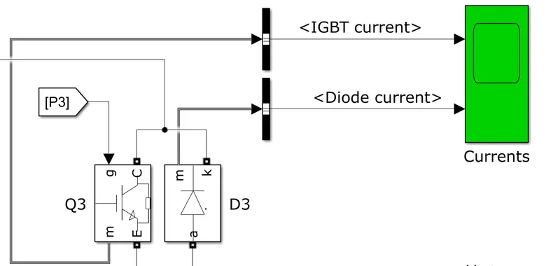
From this circuit we can measure IGBT current and diode current waveforms.The letter m in the block shows measurement either voltage or current.The IGBT and Diode current outputs are shown below:
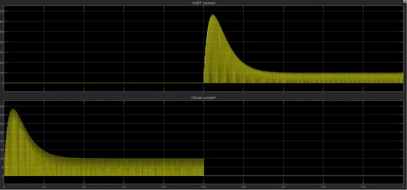
IGBT current is 0A for 0.5 time and increases exponentially to 65A and gradually reduces and stays for 11A.
Diode current increases exponentially to 37A and decreases gradually and stays in 10A.
B. Comment on the armature current shoot-up from the scope results.
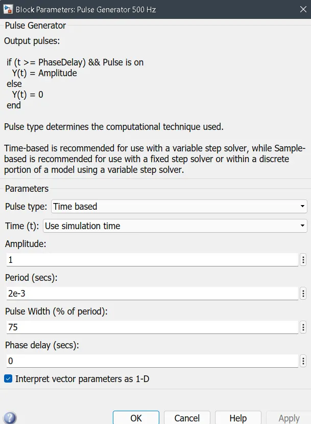
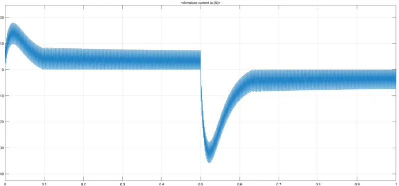
When the DC motor changes its direction from forward to reverse direction or viceversa the armature current shoots up.To avoid this shoot up the pulse width that is duty cycle of pulses from pulse generator must be decreased.Default value of Duty cycle is 75%.Reduce it to step by step and see the results:
Default case:Pulse width = 75%
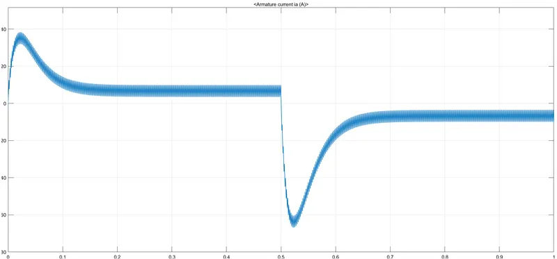
Here we can see the armature current shoots up.
Case2: Pulse width = 60%
Case 2: Pulsewidth = 50%
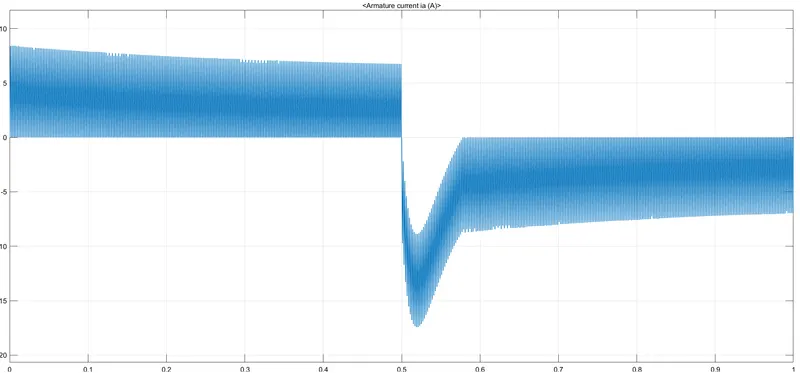
Case 3:Pulsewidth = 40%
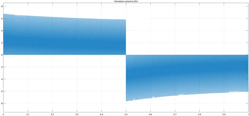
Case 4:Pulsewidth = 30%
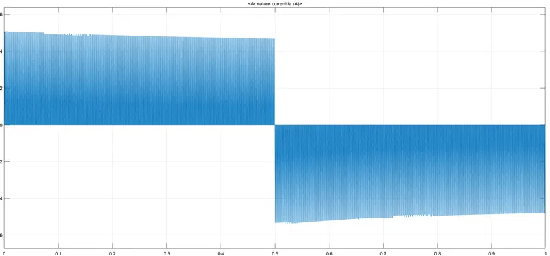
As we can see as the pulse width decreases the armature current shootup decreases.In the case 4 the armature current is almost smoother flow.The armature current shootup is due to the switching in the power circuit that causes heat emissions.These effects can be reduced by controlling pulsewidth of the pulse generated by the pulse generator.
C. Refer to the help section of ‘The Four-Quadrant Chopper DC Drive (DC7) block’. Compare it with the H-bridge model.
The four quadrant chopper or Class E chopper:
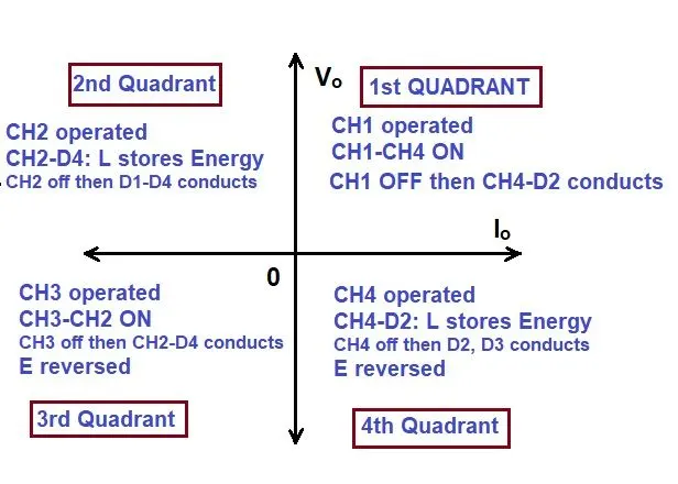
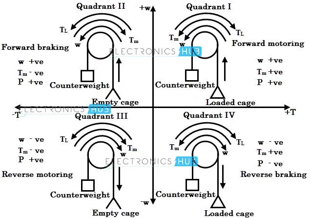
A four quadrant chopper is a chopper which can operated in all the four quadrants The power can flow either from source to load or load to source in this chopper. In first quadrant, a Class-E chopper acts as a step down chopper whereas in second quadrant it behaves as a Step up chopper This type of chopper is also known as Class-E or Type-E chopper. This article describes the working principle and operation of Class-E chopper with the help of circuit diagram:
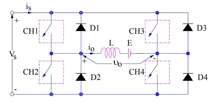
There are 4 quadrant operations:
- First quadrant operation
- Second quadrant operation
- Third quadrant operation
- Fourth quadrant operation
The simulink model for The four Quadrant Chopper DC drive is shown:
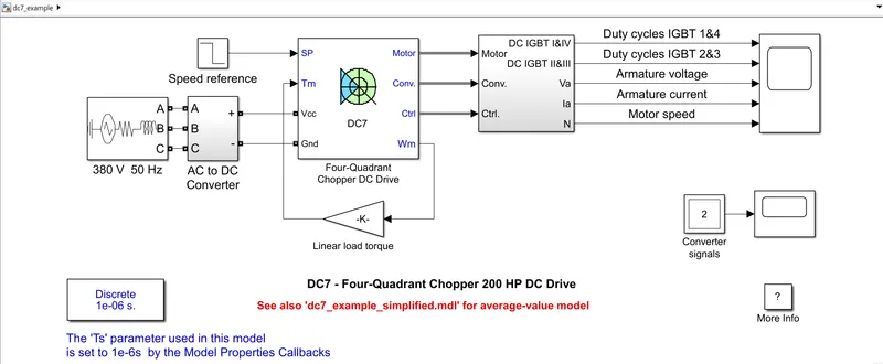
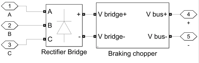
The 200 HP DC motor is separately excited with a constant 150 V DC field voltage source. The armature voltage is provided by an IGBT converter controlled by two PI regulators. The converter is fed by a 515 V DC bus obtained by rectification of a 380 V AC 50 Hz voltage source. In order to limit the DC bus voltage during dynamic braking mode, a braking chopper has been added between the diode rectifier and the DC7 block.
The first regulator is a speed regulator, followed by a current regulator. The speed regulator outputs the armature current reference (in p.u.) used by the current controller in order to obtain the electromagnetic torque needed to reach the desired speed. The speed reference change rate follows acceleration and deceleration ramps in order to avoid sudden reference changes that could cause armature over-current and destabilize the system. The current regulator controls the armature current by computing the appropriate duty ratios of the 5 kHz pulses of the four IGBT devices (Pulse Width Modulation). For proper system behaviour, the instantaneous pulse values of IGBT devices 1 and 4 are opposite to those of IGBT devices 2 and 3. This generates the average armature voltage needed to obtain the desired armature current. In order to limit the amplitude of the current oscillations, a smoothing inductance is placed in series with the armature circuit
The input signal is 380V 50Hz 3 phase AC supply and this voltage is converted to DC supply using a AC to DC converter.
AC to DC converter:
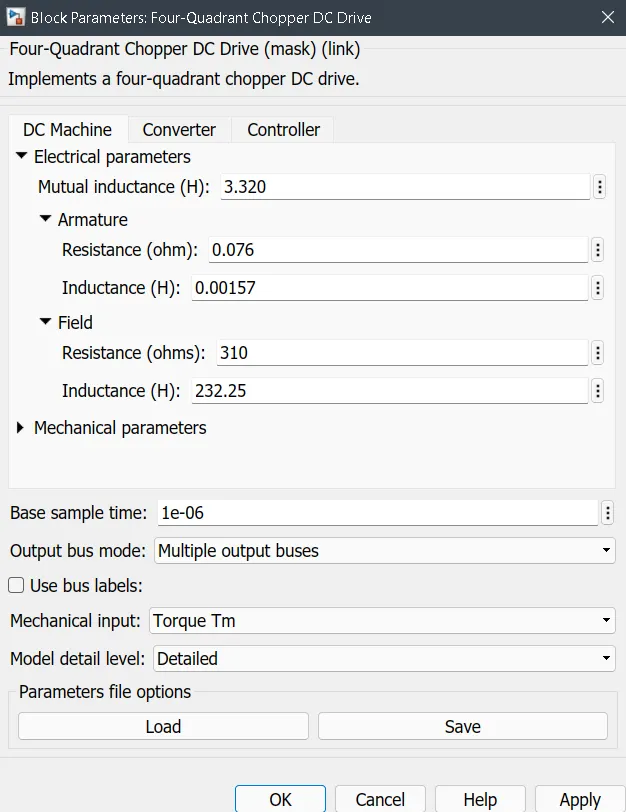
The 4 quadrant chopper having the following block parameters:
Output DC supply is given to the 4 quadrant chopper,step input having initial value 500 with step time 2 is given as speed reference.The speed output in rad/s is fed back to the block ,speed is converted back to torque using the gain block .
Output plot is shown:
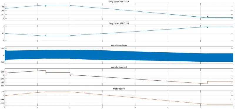
The Duty cycles of IGBT 1,2,3,4 is shown above and the armature voltage ,armature current,and motor speed vs time is plotted.
The Four-Quadrant Chopper DC Drive vs H-brideg model:
| Four Quadrant chopper | BJT H-bridge |
|
|
2. Develop a 2-quadrant chopper using simulink & explain the working of the same with the relevant results. (Refer to article - Multiquadrant operation of motor )
The basic circuit diagram for 2 quadrant chopper or Class C chopper is shown below:
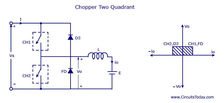
Type C chopper is obtained by connecting type –A and type –B choppers in parallel. We will always get a positive output voltage V0 as the freewheeling diode FD is present across the load. When the chopper is on the freewheeling diode starts conducting and the output voltage v0 will be equal to Vs . The direction of the load current i0 will be reversed. The current i0 will be flowing towards the source and it will be positive regardless the chopper is on or the FD conducts. The load current will be negative if the chopper is or the diode D2 conducts. We can say the chopper and FD operate together as type-A chopper in first quadrant. In the second quadrant, the chopper and D2 will operate together as type –B chopper.The average voltage will be always positive but the average load current might be positive or negative. The power flow may be life the first quadrant operation ie from source to load or from load to source like the second quadrant operation.The two choppers should not be turned on simultaneously as the combined action my cause a short circuit in supply lines. For regenerative braking and motoring these type of chopper configuration is used.
The simulink model for the 4-Quadrant chopper (Class c chopper) is shown below:
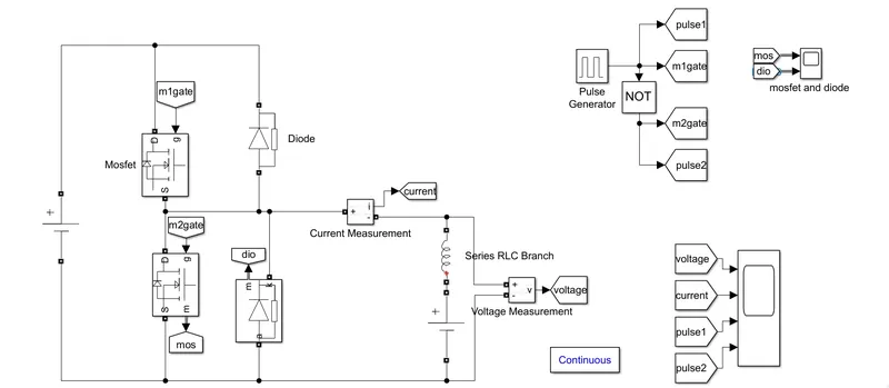
The DC voltage source connected is 24V .Here two mosfets are used and gate input of both mosfets donot collide each other.That is if MOSFET1 has value 1 the MOSFET2 value must be 0 and viceversa.The motor load is considered as LE load ie, inductor and a voltage source having 12V DC supply.
Here a MOSFET is used as the switching device which has the following specifications:
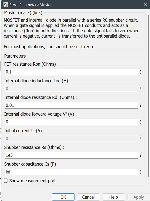
MOSFET:
MOSFET (Metal Oxide Semiconductor Field Emission Transistor) and internal diode in parallel with a series RC snubber circuit. When a gate signal is applied the MOSFET conducts and acts as a resistance (Ron) in both directions. If the gate signal falls to zero when current is negative, current is transferred to the antiparallel diode.
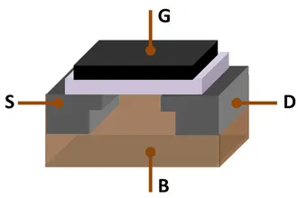
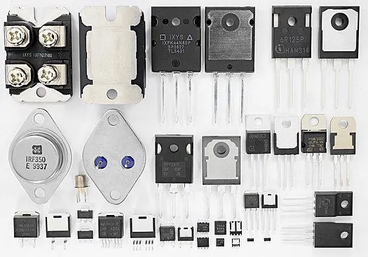
Typically mosfets have switching frequency of arround 25–500kHz
Diode:
Implements a diode in parallel with a series RC snubber circuit.In on-state the Diode model has an internal resistance (Ron) and inductance (Lon).
Current measurement:
Ideal current measurement. The Output signal parameter is disabled when the block is not used in a phasor simulation. The phasor simulation is activated by a Powergui block placed in the model.
Voltage measurement:
Ideal voltage measurement. The Output signal parameter is disabled when the block is not used in a phasor simulation. The phasor simulation is activated by a Powergui block placed in the model.
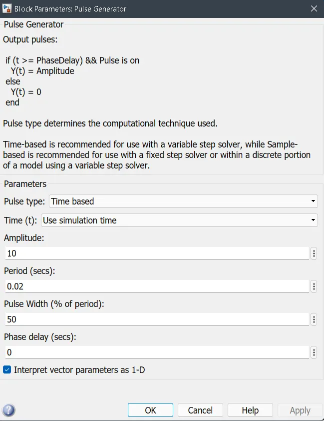
Pulse generator:
It is used to generate pulses of amplitude 10 having pulse width 50% .It is required to operate the MOSFET.Gate pulses are given by this pulse generator.Then only MOSFET works properly.
OUtput: Voltage,Current,Pulse generator output
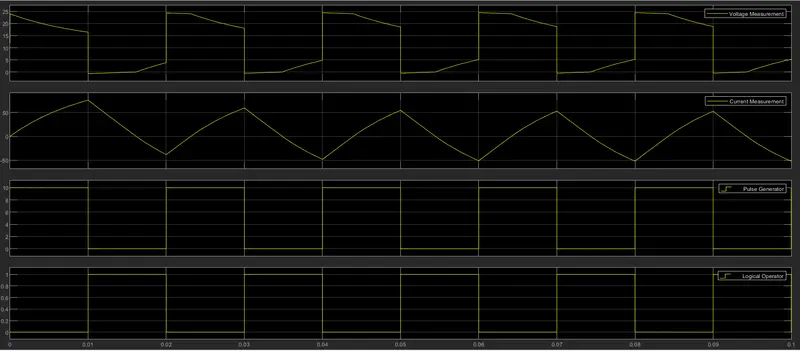
As the load voltage is high the load current increases and as the load voltage decays the load current also decreases.That is when voltage is high the inductor stores energy and when low it emits the stored energy.
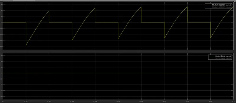
Output plot : Mosfet current and diode current
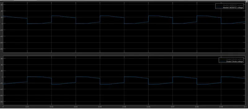
Output plot : Mosfet voltage and diode voltage
3. Explain in a brief about operation of BLDC motor.
A brushless DC electric motor (BLDC motor or BL motor), also known as an electronically commutated motor (ECM or EC motor) or synchronous DC motor, is a synchronous motor using a Direct Current (DC) electric power supply. It uses an electronic controller to switch DC currents to the motor windings producing magnetic fields which effectively rotate in space and which the permanent magnet rotor follows. The controller adjusts the phase and amplitude of the DC current pulses to control the speed and torque of the motor. This control system is an alternative to the mechanical commutator (brushes) used in many conventional electric motors.
The construction of a brushless motor system is typically similar to a prmanent magnet synchronous motor (PMSM), but can also be a switched reluctance motor, or an induction synchronous motor. They may also use neodymium magnets and be outrunners (the stator is surrounded by the rotor), inrunners (the rotor is surrounded by the stator), or axial (the rotor and stator are flat and parallel).
The advantages of a brushless motor over brushed motor are high power-to-weight ratio, high speed, nearly instantaneous control of speed (rpm) and torque, high efficiency, and low maintenance. Brushless motors find applications in such places as computer peripherals (disk drives, printers), hand-held power tools, and vehicles ranging from model aircraft to automobiles. In modern washing machines, brushless DC motors have allowed replacement of rubber belts and gearboxes by a direct-drive design.
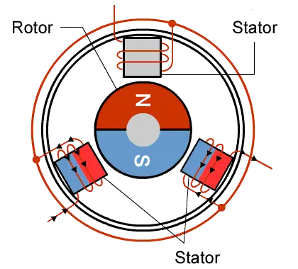
- no starting torque when directly connected to fixed frequency utility power
- needs inverter whose phase is maintained in step with angular position of rotor
- Drives require position sensor- less heat is released,rotor cooling is easy,peak point efficiency is high
- can work at 100% power factor
- In ideal BLDC drives strength of magnetic field produced by permanent magnet is adjustable
- magnetic field cant be adjusted because PM is used
- As machine size increases looses efficiency due to high losses but it has good stability over Torque - Speed region and less heat is emitted
- Dominates in HEV,PHEV
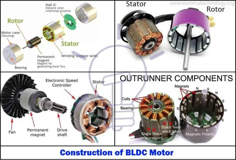
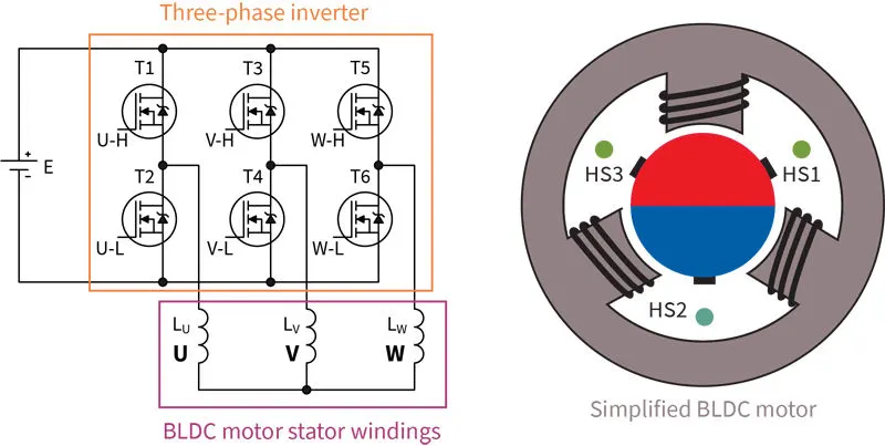
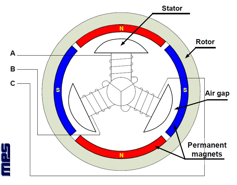
Semiconductor control is used for controlling the stator current in such a way that maximum torque is obtained at a given speed. The stator has three-phase winding while the rotor is in the form of a permanent magnet.The rotor is the part of the machine that will rotate and the stator is the part of the machine that will remain a constant in the stationary part of the machine.Speed can be controlled by controlling the stator of the machine which can be achieved by controlling the dc input voltage of the inverter. The shaft is the rotating part that is connected to the different types of load driven by the motor.
BLDC motor also consists of rotor position sensors that produce electrical signals that indicate the current position of the rotor. The stator winding of the BLDC motor is driven from an electronic drive which is a three-phase inverter.
The permanent magnet brushless DC motors use Hall sensors with 60 degrees electrical spacing. These sensors produce a logic 1 when exposed to the N-type of the rotor and logic 0 otherwise.
In the BLDC motor,
- The fields produced by the stator and rotor remain stationary with respect to each other.
- The driver circuit operates on a dc supply.
Advantages:
1. The absence of brushes reduces the frequent replacement of brushes which reduces the maintenance cost.
3. The lifespan of a Brushless DC motor is higher than the brushed DC motor.
4. Sparking is reduced due to the absence of brushes and there is a few chances of burnout due to sparking issues.
5. A Brushless DC motor provides high torque to speed ratio which is best suited for robotics and medical applications.
7.It follows a feedback control system that has the ability to modify and control the speed and torque.
8. These motors are suitable to run either in a low load or no-load.
10.These motors are used in electrical applications where less noise is required.
Disadvantages:
1. Brushless DC motors are operated at relatively low speeds. Due to this low-speed vibrations occurs in the system.
2. The cost of these motors is high.
3. As these motors consist of a feedback loop the wiring and operation are not that simple.
6. It needs three hall effect sensors to measure rotor position.
Applications:
1. Brushless DC motors are used in hybrid vehicles, electric vehicles, and other electrical equipment.
2. These motors are used in robotics for robotic arms.
3. BLDC motors are used in computer hard drives and DVD players.
4. These motors are used in fans, washing machines, dryers, pumps, blowers, and compressors.