Project 1
6kW SEPIC CONVERTER in CCM
SEPIC means Single-Ended Primary Inductance Converter having a positive output polarity.
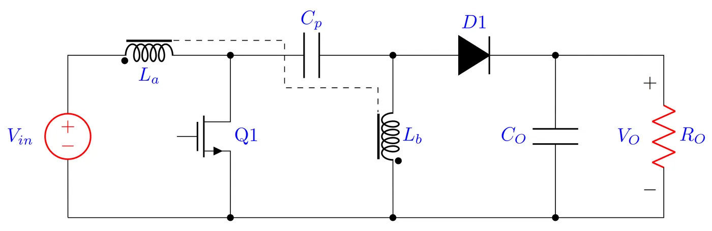
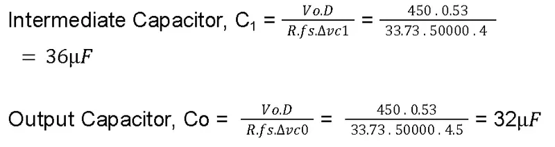
Design steps:
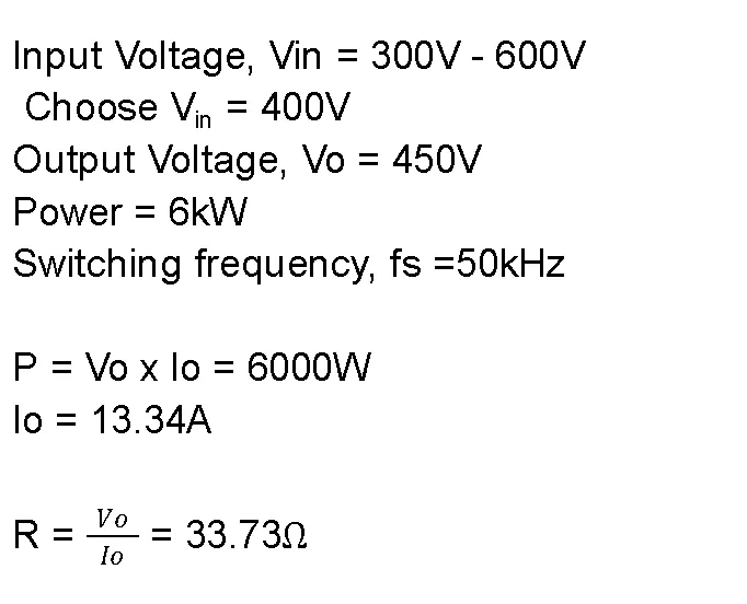
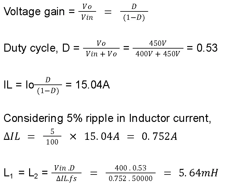
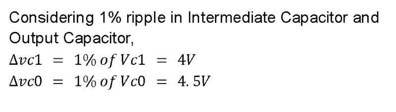
Model-Based Design in Simulink:
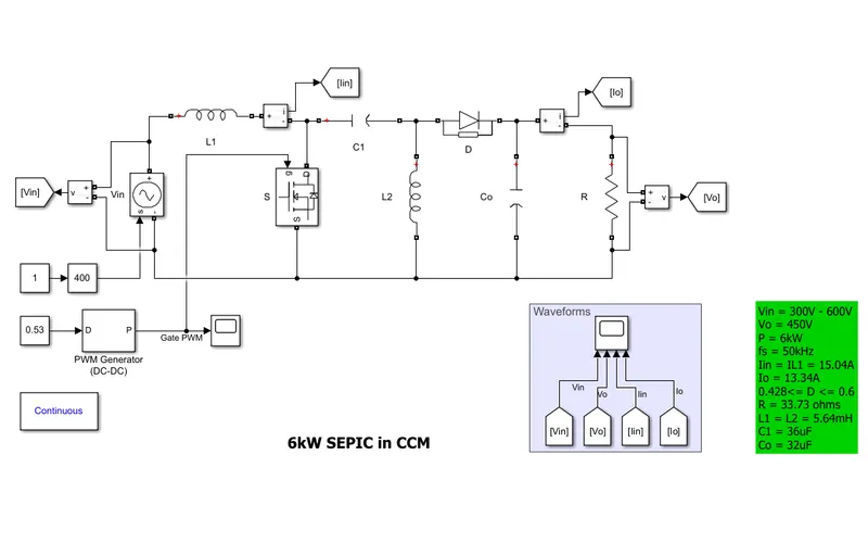
Waveforms:
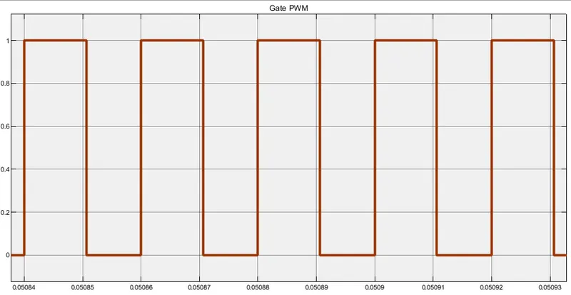
Gate pulse for MOSFET having a 53% duty ratio:
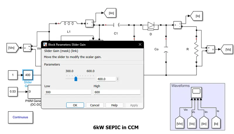
Input Voltage can be varied using the slider:
Input and Output Voltage:
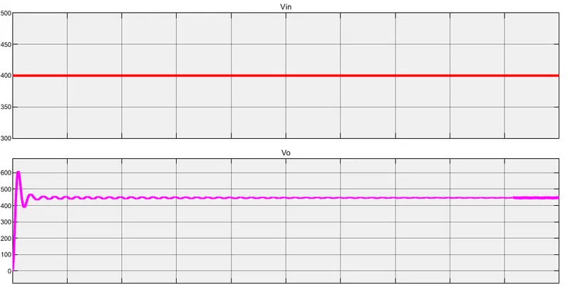
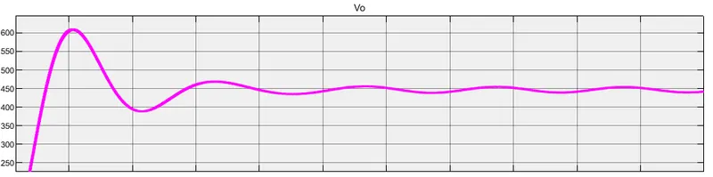
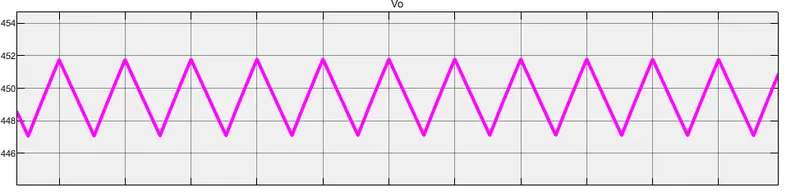
At steady-state the average output voltage is around 450V
Input Current, Iin and Output current, Io:
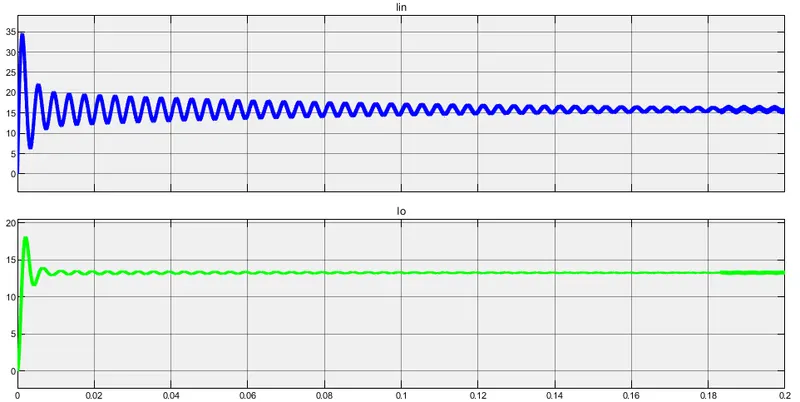

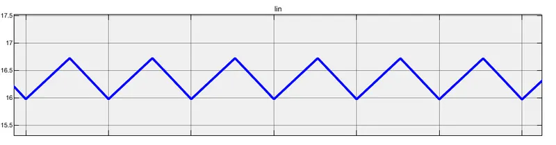
At steady-state the average input current is around 16.5A
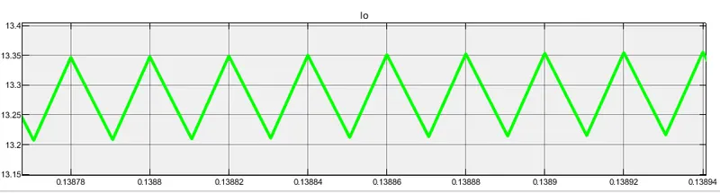
At steady-state, the average output current is around 13.3A.
Hence the mentioned 6kW SEPIC is designed, simulated, and analyzed.
300W Inverting Buck-Boost Converter:
Applications:
-
Negative Voltage Generation: The primary application of inverting Buck-Boost converters is to generate a negative output voltage from a positive input voltage. This is useful in various electronic circuits that require both positive and negative supply voltages.
-
Bipolar Power Supplies: Inverting Buck-Boost converters are used in applications where bipolar power supplies are needed, such as in audio amplifiers, operational amplifier circuits, and other analog signal processing circuits.
-
LCD Biasing: Some LCD (Liquid Crystal Display) panels require a negative voltage bias, and inverting Buck-Boost converters are used to generate the necessary negative voltage from a positive input source.
-
Telecommunication Systems: In telecommunication equipment and systems, inverting Buck-Boost converters can be used for generating the negative voltage rails needed by certain components or circuits.
-
Audio Systems: Inverting Buck-Boost converters find applications in audio systems, particularly in portable audio devices and audio amplifiers, where negative voltages are required for biasing or signal processing.
-
Automotive Electronics: In automotive applications, inverting Buck-Boost converters can be used to generate negative voltage rails for specific electronic components or sensors.
-
Industrial Control Systems: Inverting Buck-Boost converters are utilized in various industrial control systems where negative voltage requirements exist.
-
Battery-Powered Devices: Inverting Buck-Boost converters are employed in battery-powered devices that need both positive and negative supply voltages for different circuit elements.
-
Biasing Circuitry: Inverting Buck-Boost converters can be used in biasing circuitry for certain electronic components like transistors or sensors that require negative voltage biases.
-
Medical Electronics: In some medical devices and equipment, inverting Buck-Boost converters are used to generate the necessary negative supply voltages for specific applications.
Design steps:
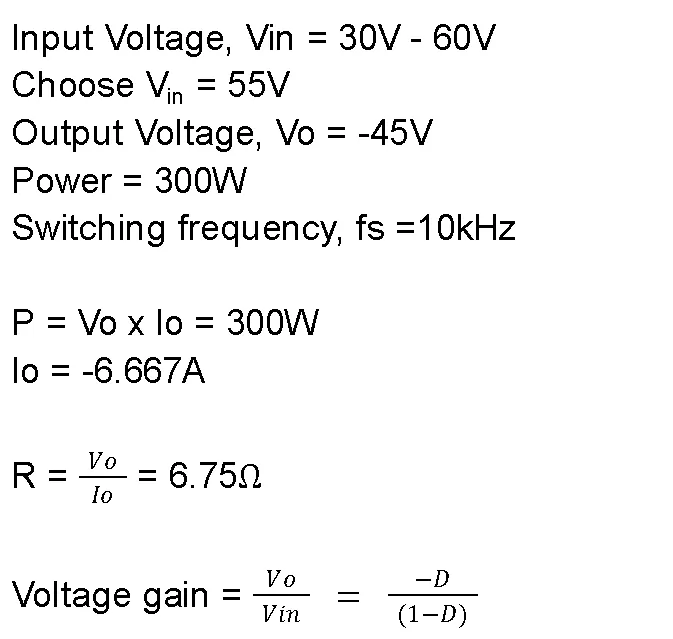
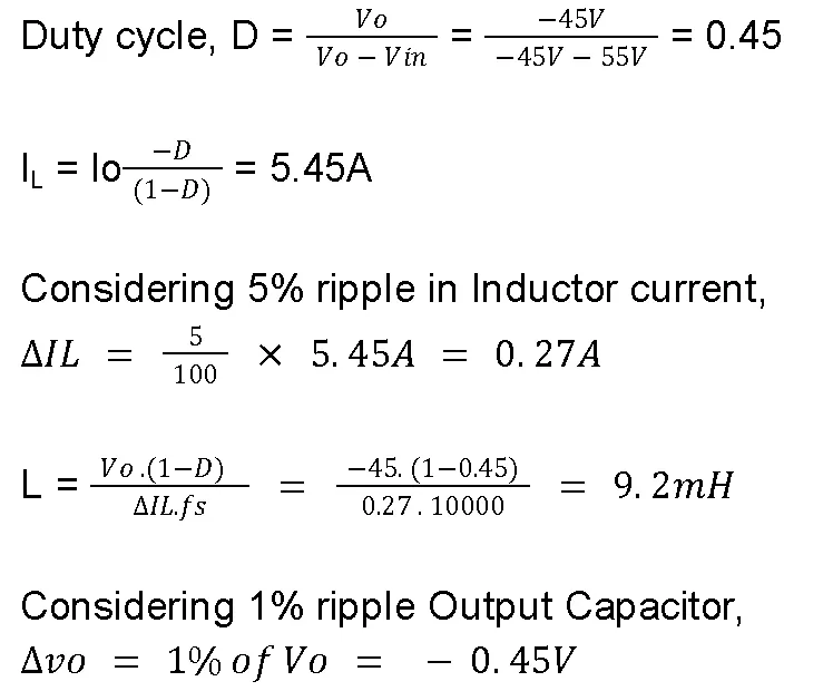

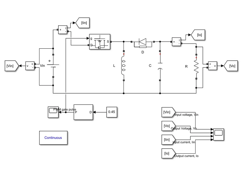
Inverting Buck-Boost converter in Simulink:
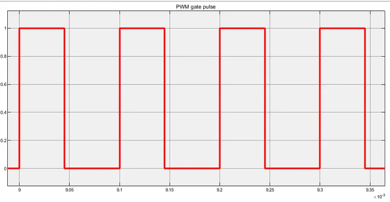
PWM gate pulse having 45% duty ratio for Mosfet:
Input Voltage and Output Voltage:
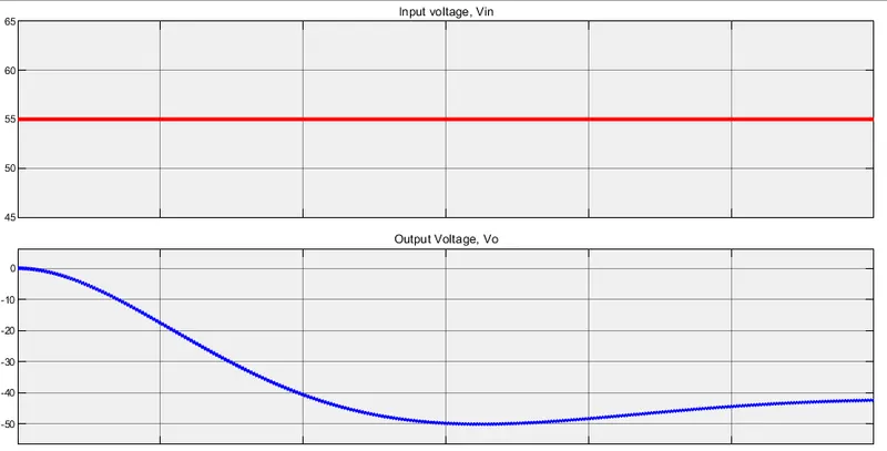
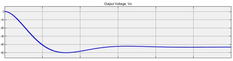
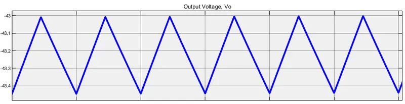
At steady-state the average output voltage is around -43V
Input Current vs Output current:
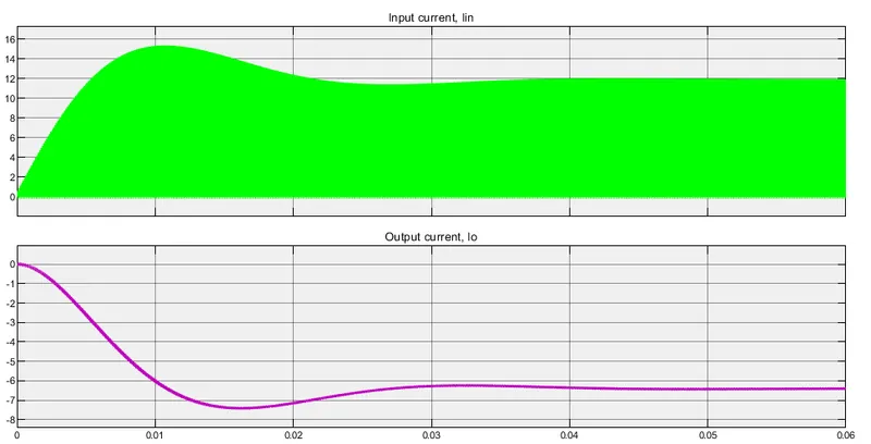
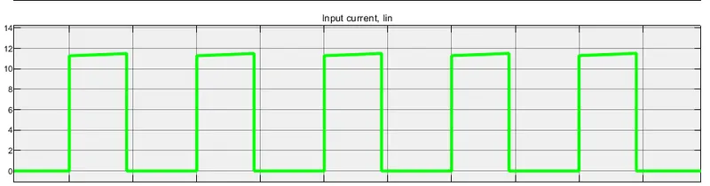
At steady-state the average input current is 6A
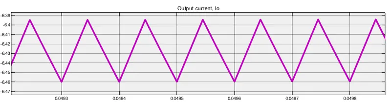
At steady-state the output current is around -6.4A.
Hence Inverting Buck-Boost converter is designed and simulated in Matlab/Simulink.
BUCK CONVERTER IN DCM :
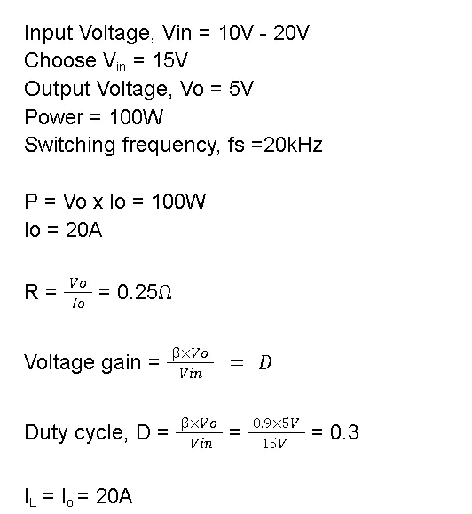
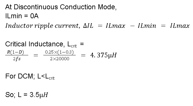
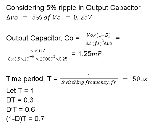
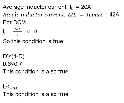
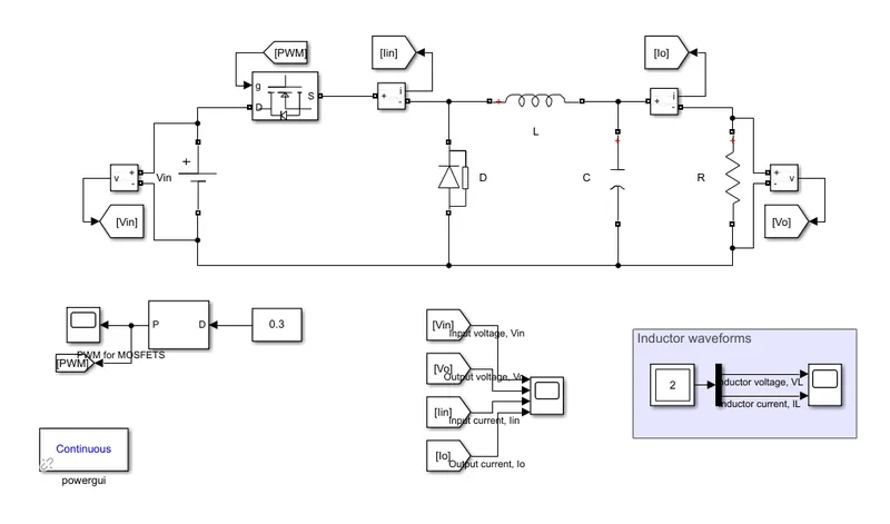
Buck converter in DCM designed in Simulink:
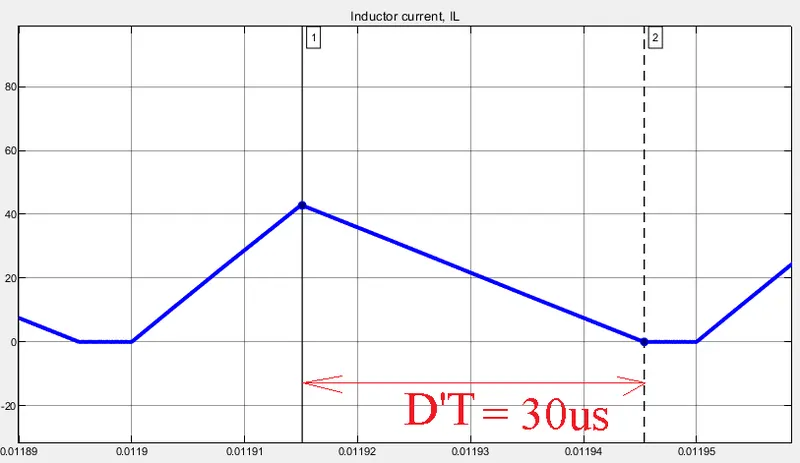
Waveforms:
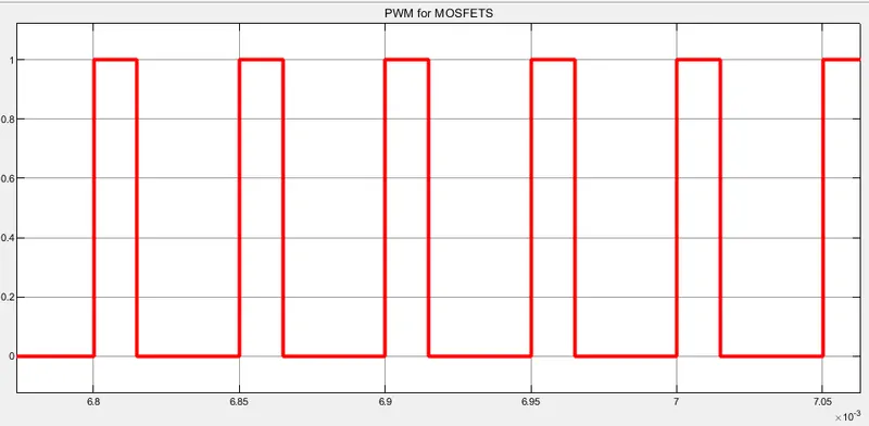
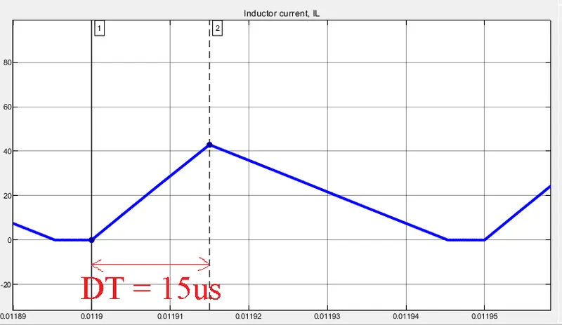
D = 0.3
Input Voltage and Output Voltage:
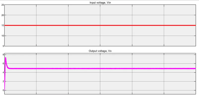
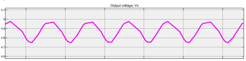
Average Output Voltage, Vo = 4.9V
Input Current and Output current:
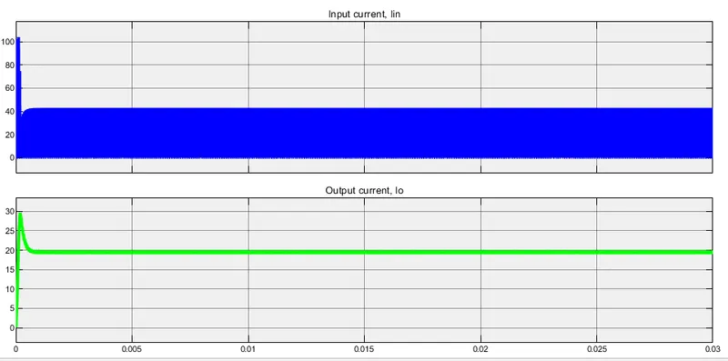
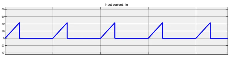
This is the current in the switch, MOSFET conducts only during DT period. Here the peak current = ILmax = 42A
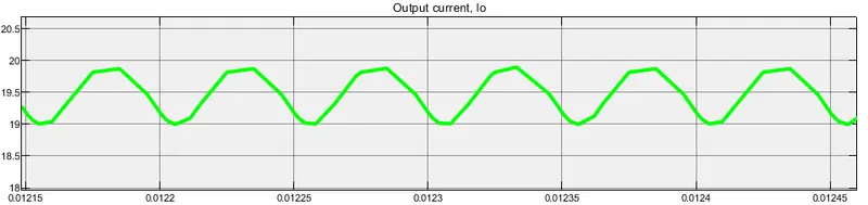
The output current is around 19.5A.
Inductor voltage and current:

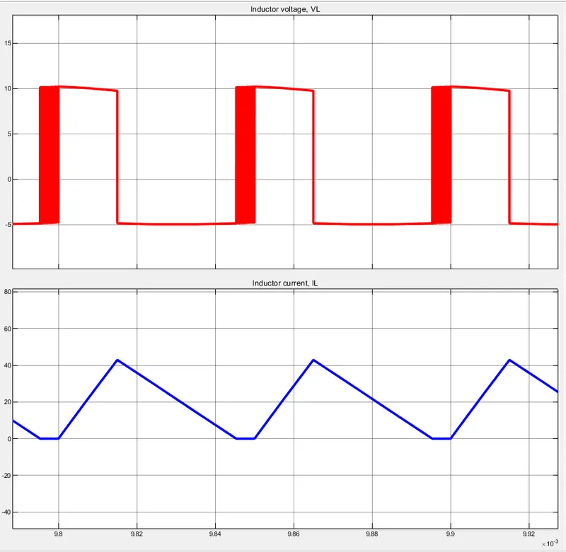
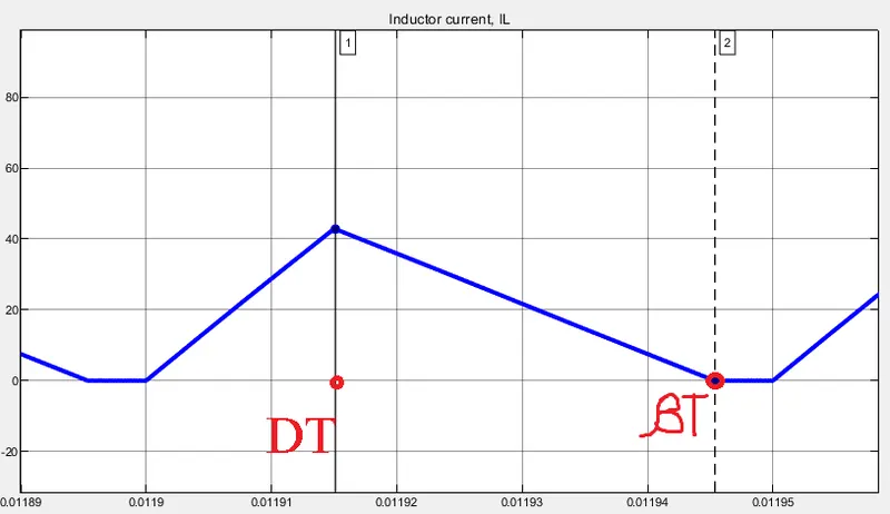
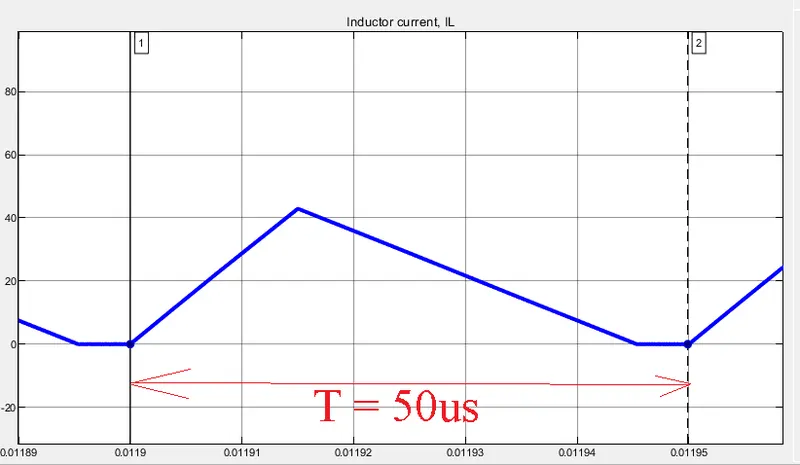
Here we can clearly see that the Inductor current is discontinuous for (T - `beta` T) period.
Hence designed and simulated a 100W Buck converter working in Discontinuous Conduction Mode in Simulink.