Project-1: Powertrain for aircraft in runways
Powertrain for aircraft in runways
Part A:
1)Search and list out the total weight of various types of aircrafts.
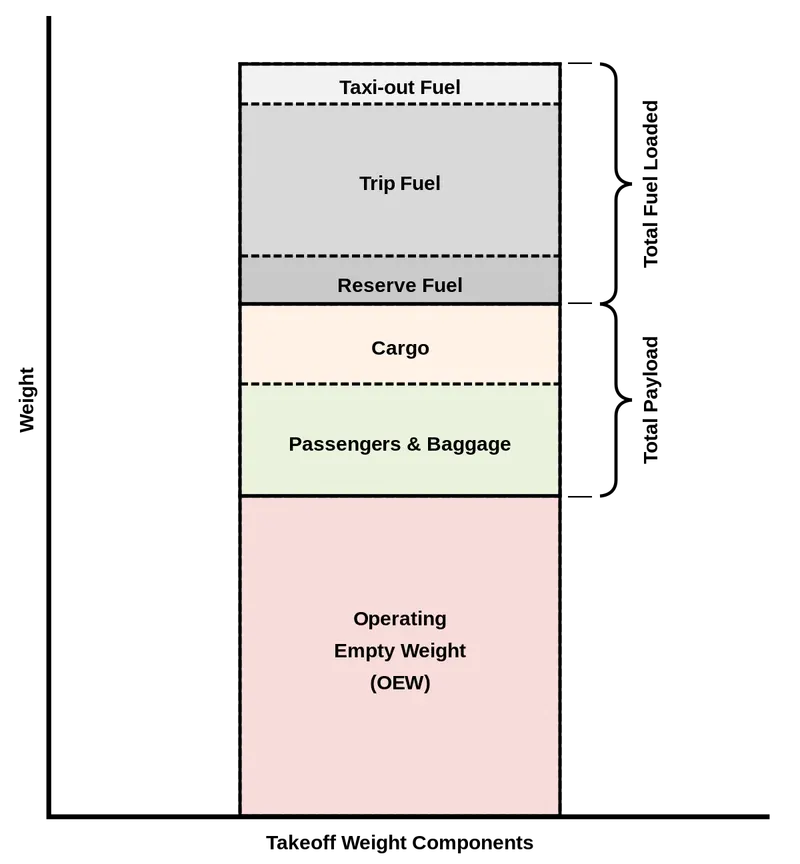
The Federal Aviation Administration defines that the aircraft gross weight (also known as the all-up weight and abbreviated AUW) is the total aircraft weight at any moment during the flight or ground operation.An aircraft's gross weight will decrease during a flight due to fuel and oil consumption. An aircraft's gross weight may also vary during a flight due to payload dropping or in-flight refuelling.At the moment of releasing its brakes, the gross weight of an aircraft is equal to its takeoff weight. During flight, an aircraft's gross weight is referred to as the en-route weight or in-flight weight.
MTOW = Maximum take-off weight
MLW = Maximum landing weight
TOR = Take-off run
LR = Landing run (SL, ISA+15°, MLW)
| Type | MTOW [kg] | MLW [tonnes] | TOR [m] | LR [m] | ICAO category | FAA category |
|---|---|---|---|---|---|---|
| Airbus A220-100 | 59,000 | 50.80 | 1463 | 1356 | Medium | Large |
| Airbus A220-300 | 65,000 | 57.61 | 1890 | 1494 | Medium | Large |
| Airbus A300-600 | 163,000 | 138 | 2324 | 1536 | Heavy | Heavy |
| Airbus A300-600R | 192,000 | 140 | 2385 | 1555 | Heavy | Heavy |
| Airbus A310-200 | 142,000 | 123 | 1860 | 1480 | Heavy | Heavy |
| Airbus A310-300 | 157,000 | 124 | 2290 | 1490 | Heavy | Heavy |
| Airbus A318 | 59,000 | 57.5 | 1375 | 1340 | Medium | Large |
| Airbus A319 | 64,000 | 62.5 | 1850 | 1470 | Medium | Large |
| Airbus A320-100 | 68,000 | 66 | 1955 | 1490 | Medium | Large |
| Airbus A321-100 | 83,000 | 77.8 | 2200 | 1540 | Medium | Large |
| Airbus A330-200 | 242,000 | 180 | 2220 | 1750 | Heavy | Heavy |
| Airbus A330-300 | 242,000 | 185 | 2500 | 1750 | Heavy | Heavy |
| Airbus A330-900 | 251,000 | 191 | 3100 | Heavy | Heavy | |
| Airbus A340-200 | 253,500 | 181 | 2990 | Heavy | Heavy | |
| Airbus A340-300 | 276,700 | 190 | 3000 | 1926 | Heavy | Heavy |
| Airbus A340-500 | 371,950 | 240 | 3050 | 2010 | Heavy | Heavy |
| Airbus A340-600 | 367,400 | 256 | 3100 | 2100 | Heavy | Heavy |
| Airbus A350-900 | 270,000 | 175 | 2670 | 1860 | Heavy | Heavy |
| Airbus A350-1000 | 308,000 | 233.5 | Heavy | Heavy | ||
| Airbus A380-800 | 575,000 | 394 | 3100 | 1930 | Heavy | Super |
| Airbus A400M | 141,000 | 122 | 980 | 770 | Heavy | Heavy |
| Antonov An-124-100M | 405,060 | 330 | 2520 | 900 | Heavy | Heavy |
| Antonov An-225 | 640,000 | 591.7 | 3500 | Heavy | Super | |
| ATR 42-500 | 18,600 | 18.3 | 1165 | 1126 | Medium | Small |
| ATR 72-600 | 22,800 | 22.35 | 1333 | 914 | Medium | Large |
| Avro RJ-85 | 42,000 | 36.74 | Medium | Large | ||
| BAe Jetstream 41 | 10,890 | 10.570 | 1493 | 826 | Medium | Small |
| Beechcraft 1900D | 7,765 | 7.605 | 1036 | 853 | Medium | Small |
| Boeing 377 | 67,000 | Medium | Large | |||
| Boeing 707-120B | 117,000 | 86.3 | Medium | Large | ||
| Boeing 707-320B | 151,000 | 97.5 | Heavy | Heavy | ||
| Boeing 707-320C | 151,000 | 112.1 | Heavy | Heavy | ||
| Boeing 717-200BGW | 50,000 | 46.265 | 1950 | Medium | Large | |
| Boeing 717-200HGW | 55,000 | 47.174 | 1950 | Medium | Large | |
| Boeing 720 | 104,000 | 79.5 | Medium | Large | ||
| Boeing 720B | 106,000 | 79.5 | Medium | Large | ||
| Boeing 727-100 | 72,500 | 62.4 | Medium | Large | ||
| Boeing 727-100C | 72,500 | 62.4 | Medium | Large | ||
| Boeing 727-200 | 78,000 | 68.1 | Medium | Large | ||
| Boeing 727-200 Advanced | 84,000 | 70.1 | Medium | Large | ||
| Boeing 737-300 | 63,000 | 51.7 | 1939 | 1396 | Medium | Large |
| Boeing 737-400 | 68,000 | 54.9 | 2540 | 1540 | Medium | Large |
| Boeing 737-500 | 60,000 | 49.9 | 1832 | 1360 | Medium | Large |
| Boeing 737-600 | 66,000 | 54.66 | 1796 | 1340 | Medium | Large |
| Boeing 737-700 | 70,000 | 58.06 | 1921 | 1415 | Medium | Large |
| Boeing 737-800 | 79,000 | 65.32 | 2308 | 1634 | Medium | Large |
| Boeing 737-900 | 85,000 | 66.36 | 2500 | 1704 | Medium | Large |
| Boeing 737-900ER | 85,000 | 71.35 | 2804 | 1829 | Medium | Large |
| Boeing 747-8 | 443,613 | 306.175 | 3100 | Heavy | Heavy | |
| Boeing 747-8F | 447,700 | 346.091 | 3100 | 1800 | Heavy | Heavy |
| Boeing 747-100 | 340,200 | 265.300 | Heavy | Heavy | ||
| Boeing 747-200 | 377,840 | 285.700 | 3338 | 2109 | Heavy | Heavy |
| Boeing 747-300 | 377,840 | 260.320 | 3222 | 1905 | Heavy | Heavy |
| Boeing 747-400 | 396,900 | 295.742 | 3018 | 2179 | Heavy | Heavy |
| Boeing 747-400ER | 412,770 | 295.742 | 3090 | Heavy | Heavy | |
| Boeing 757-200 | 116,000 | 89.9 | 2347 | 1555 | Medium | Large |
| Boeing 757-300 | 124,000 | 101.6 | 2550 | 1750 | Medium | Large |
| Boeing 767-300 | 159,000 | 136.078 | 2713 | 1676 | Heavy | Heavy |
| Boeing 767-300ER | 187,000 | 136.08 | 2713 | 1676 | Heavy | Heavy |
| Boeing 767-400ER | 204,000 | 158.758 | 3414 | Heavy | Heavy | |
| Boeing 777-200ER | 297,550 | 213.00 | 3380 | 1550 | Heavy | Heavy |
| Boeing 777-200LR | 347,450 | 223.168 | 3000 | Heavy | Heavy | |
| Boeing 777-300 | 299,370 | 237.683 | 3380 | Heavy | Heavy | |
| Boeing 777-300ER | 351,800 | 251.29 | 3100 | Heavy | Heavy | |
| Boeing 777F | 347,800 | 260.816 | 2830 | Heavy | Heavy | |
| Boeing 787-8 | 228,000 | 172.365 | 3300 | 1695 | Heavy | Heavy |
| Boeing 787-9 | 254,000 | 192.777 | 2900 | Heavy | Heavy | |
| Boeing 787-10 | 254,000 | 201.849 | Heavy | Heavy | ||
| Bombardier CRJ200 | 23,000 | 21.319 | 1918 | 1479 | Medium | Large |
| Bombardier CRJ700 | 33,000 | 30.39 | 1564 | 1478 | Medium | Large |
| Bombardier CRJ900 | 36,500 | 33.345 | 1778 | 1596 | Medium | Large |
| Bombardier Q400 | 28,000 | 28.01 | 1219 | 1295 | Medium | Large |
| Caravelle III | 46,000 | Medium | Large | |||
| Cessna Citation CJ4 | 7,761 | 7.103 | 1039 | 896 | Medium | Small |
| Concorde | 185,000 | 111.1 | 3440 | 2220 | Heavy | Heavy |
| Convair 880 | 87,500 | Medium | Large | |||
| de Havilland Comet 1 | 50,000 | Medium | Large | |||
| de Havilland Comet 2 | 54,000 | Medium | Large | |||
| de Havilland Comet 3 | 68,000 | Medium | Large | |||
| de Havilland Comet 4 | 70,700 | Medium | Large | |||
| de Havilland Hercules | 7,000 | Medium | Small | |||
| Douglas DC-4 | 33,000 | Medium | Large | |||
| Douglas DC-6 | 44,000 | Medium | Large | |||
| Douglas DC-6A | 48,600 | Medium | Large | |||
| Douglas DC-6B | 48,500 | Medium | Large | |||
| Douglas DC-7 | 55,000 | Medium | Large | |||
| Douglas DC-8-32 | 140,000 | Heavy | Heavy | |||
| Douglas DC-8-51 | 125,000 | Medium | Large | |||
| Douglas DC-8-61 | 147,000 | Heavy | Heavy | |||
| Embraer 120 Brasilia | 11,500 | 11.25 | 1560 | 1380 | Medium | Small |
| Embraer 170 | 36,000 | 32.8 | 1644 | 1274 | Medium | Large |
| Embraer 175 | 37,500 | 32.8 | 2244 | 1304 | Medium | Large |
| Embraer 190 | 48,000 | 43 | 2056 | 1323 | Medium | Large |
| Embraer ERJ 145 | 22,000 | 19.3 | 2270 | 1380 | Medium | Large |
| Embraer Phenom 100 | 4,800 | 4.43 | 975 | 741 | Light | Small |
| Embraer Phenom 300 | 8,150 | 7.65 | 956 | 677 | Medium | Small |
| Fokker 100 | 46,000 | 39.95 | 1621 | 1350 | Medium | Large |
| Handley Page Hermes | 39,000 | Medium | Large | |||
| Hawker Siddeley Trident 2E | 65,000 | Medium | Large | |||
| Ilyushin IL-86 | 208,000 | 175 | Heavy | Heavy | ||
| Ilyushin IL-96-300 | 250,000 | 175 | 2600 | 1980 | Heavy | Heavy |
| Ilyushin Il-96M | 270,000 | 195.04 | 3115 | 2118 | Heavy | Heavy |
| Learjet 75 | 9,752 | 8.709 | 1353 | 811 | Medium | Small |
| Lockheed C-5 Galaxy | 381,000 | 288.417 | 2530 | 1494 | Heavy | Heavy |
| Lockheed L-1011-200 | 211,400 | Heavy | Heavy | |||
| Lockheed L-1011-500 | 231,300 | 166.92 | 2636 | Heavy | Heavy | |
| McDonnell Douglas DC-10 | 256,280 | 183 | 2990 | 1890 | Heavy | Heavy |
| McDonnell Douglas MD-11 | 273,300 | 185 | 2990 | 1890 | Heavy | Heavy |
| McDonnell-Douglas MD-83 | 73,000 | 63.28 | Medium | Large | ||
| McDonnell-Douglas MD-90-30 | 71,000 | 64.41 | 2165 | 1520 | Medium | Large |
| Pilatus PC-24 | 8,300 | 7.665 | 893 | 724 | Medium | Small |
| Saab 340 | 13,150 | 12.930 | 1300 | 1030 | Medium | Small |
| Saab 2000 | 22,800 | 21.5 | 1300 | Medium | Large | |
| Scaled Composites Model 351 Stratolaunch | 589,670 | 3660 | Heavy | Super | ||
| Tupolev Tu-154M | 104,000 | 80 | Medium | Large | ||
| Tupolev Tu-204SM | 104,000 | 87.5 | 2250 | Medium | Large | |
| Vickers VC10 | 152,000 | 151.9 | Heavy | Heavy | ||
| Vickers Viscount 800 | 30,400 | Medium | Large |
2)Is there any difference between ground speed and air speed?
Ground speed:
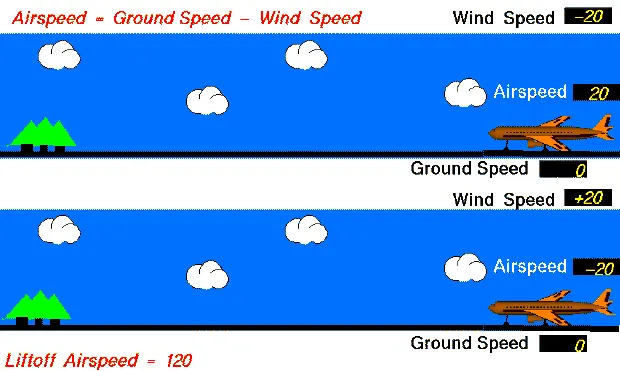
Ground speed is the horizontal speed of an aircraft relative to the Earth’s surface. It is vital for accurate navigation that the pilot has an estimate of the ground speed that will be achieved during each leg of a flight. An aircraft diving vertically would have a ground speed of zero.An aircraft diving vertically would have a ground speed of zero. Information displayed to passengers through the entertainment system of airline aircraft usually gives the aircraft ground speed rather than airspeed.Ground speed can be determined by the vector sum of the aircraft's true airspeed and the current wind speed and direction; a headwind subtracts from the ground speed, while a tailwind adds to it. Winds at other angles to the heading will have components of either headwind or tailwind as well as a crosswind component.An airspeed indicator indicates the aircraft's speed relative to the air mass. The air mass may be moving over the ground due to wind, and therefore some additional means to provide position over the ground is required. This might be through navigation using landmarks, radio aided position location, inertial navigation system, or GPS. When more advanced technology is unavailable, an E6B flight computer may be used to calculate ground speed. Ground speed radar can measure it directly.Ground speed is quite different from airspeed. When an aircraft is airborne the ground speed does not determine when the aircraft will stall, and it doesn't influence the aircraft performance such as rate of climb.
Air speed:
In aviation, airspeed is the speed of an aircraft relative to the air. Among the common conventions for qualifying airspeed are:
1.Indicated airspeed ("IAS"), what is read on an airspeed gauge connected to a Pitot-static system;
2.Calibrated airspeed ("CAS"), indicated airspeed adjusted for pitot system position and installation error;
3.Equivalent airspeed ("EAS"), calibrated airspeed adjusted for compressibility effects;
4.True airspeed ("TAS"), equivalent airspeed adjusted for air density, and is also the speed of the aircraft through the air in which it is flying.
Calibrated airspeed is typically within a few knots of indicated airspeed, while equivalent airspeed decreases slightly from CAS as aircraft altitude increases or at high speeds.With EAS constant, true airspeed increases as aircraft altitude increases. This is because air density decreases with higher altitude.The measurement and indication of airspeed is ordinarily accomplished on board an aircraft by an airspeed indicator ("ASI") connected to a pitot-static system. The pitot-static system comprises one or more pitot probes (or tubes) facing the on-coming air flow to measure pitot pressure (also called stagnation, total or ram pressure) and one or more static ports to measure the static pressure in the air flow. These two pressures are compared by the ASI to give an IAS reading.
| Ground speed | Air speed |
|
|
3)Why is it not recommended to use aircraft engine power to move it on the ground at Airport?
Aircraft Ground Running is usually used to describe the operation of some or all of the engines of an aircraft, whilst on the ground, for the purpose of functionally checking the operation of either engines or aircraft systems.Ground running may be carried out either prior to, during or after the rectification of a defect or scheduled work on an engine or an aircraft system, when this requires engines to be operating in order to assess its function. Although the aircraft may need to be taxied or towed to an approved ground running position under a clearance from ATC, most operators and maintenance organisations do not require pilots to be on board because aircraft technicians can be trained and approved for these duties.
- The Risk to Operational Safety
The risks which may arise from engine ground running relate to the potential for loss of control of the aircraft by those persons occupying the pilot seats in the flight deck. In most cases, such persons will be maintenance personnel holding specific company-issued approval for the required tasks. The consequences of loss of control during taxi or towing are the same as apply to these operations generally and this article is concerned only with the risks arising from the static running of one or more aircraft engines. Unwanted consequences from such static running are mainly related to those arising from the unintended movement of the aircraft during engine running - effectively a loss of control - especially during high power engine running. Damage can occur to the aircraft itself, other aircraft nearby or to airside structures. In addition, there is a risk of injury to ground support personnel who may be in relatively close proximity to the aircraft.
- Overall Risk Mitigation
The best form of overall mitigation is to ensure that all persons authorised to supervise or directly participate in engine ground running from the flight deck, who are not pilots or flight engineers currently rated on the specific aircraft type, are in receipt of suitable initial training and that there is a proper system for both initial and recurrent qualification for engine ground running duties. Both initial and recurrent qualification must include practical training and assessment of task competence using either a full flight simulator or an aircraft. Between formal competency assessments, a maximum interval between performance of the qualified task should be specified. If that interval is exceeded, the qualification would become void until remedial action has been competed. In this respect, the task of engine ground running should be seen as part of a broader group of aircraft ground movement tasks which can be carried out under the control of flight deck occupants other than type rated flight crew.
4)How an aircraft is pushed to runway when its ready to take off?
In aviation, pushback is an airport procedure during which an aircraft is pushed backwards away from its parking position, usually at an airport gate by external power. Pushbacks are carried out by special, low-profile vehicles called pushback tractors or tugs.Although many aircraft are capable of moving themselves backwards on the ground using reverse thrust (a procedure referred to as a powerback),the resulting jet blast or prop wash would cause increased noise, damage to the terminal building or equipment, and hurt airport staff due to high-speed debris.This debris would also be sucked into the engine, as it is in normal use, and cause excessive wear - a major cause of wear on aircraft engines is during ground use.A pushback is therefore the preferred method when ground-handling aircraft.
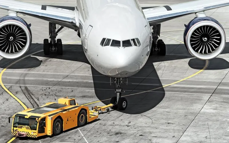
Once the aircraft commander has given their confirmation of brakes released to the person in charge of the ground crew who are to carry out the pushback, the ground crew become temporarily responisble for the safe manoeuvring of the aircraft in accordance with either promulgated standard procedures or as specifically agreed beforehand. Almost all aircraft types required that the ground locking pin be installed in the nose landing gear during any pushback. However this is now no longer always the case. If a ground locking pin is installed for the pushback, it will need to be removed after the completion of the ground vehicle manoeuvre if the airfact has been pushed back prior to intended flight.The traditional method of allowing the ground vehicle to move an aircraft is to attach it to the aircraft nose landing gear by means of a towbar. These must be approved for use with s particular aircraft type and clearly marked as such, since there is no universall towbar specification, the same towbar attachment and ground vehicle may also be used for Aircraft towing in the forward direction. An alternative method which is becoming more common for pushback is the use of a specialised vehicle called a towbarless tug. This positions two level arms either side of the aircraft nose landing gear and these are used to engage with the aircraft gear leg and raise it slightly off the ground. These specialised vehicles can also be used to tow aircraft forward.The responsibilities of the ground crew team carrying out a pusback include ensuring that no part of the aircraft structure will impact any fixed object other aircraft and my include giving clearance to start one or more engines just before, during or immediately after a pushback. Effective communication between the person in charge in the flight deck and the person in charge of the ground crew and between the members of the ground crew team is critical.
The case of engines running pull forward as a supplementary action prior to ground vehicle disconnection after a pushback should be considered as part of the pushback procedure and trained accordingly since it bears little practical resemblance to the towing for longer distances of empty out of service with engines stopped. Engines starts ay be routinely accomplished immediately before or during pushback. Many aircraft operators require that when pushback is accomplished without headset communications, engine starts do not take place whilst the aircraft is being pushed, preferring instead to require that engine starting takes place before or after completion of the pushback.For smaller aircraft, the pushback tug doen't require a massive amount of power. They utilize the weight of the tug, sometimes up to 60tons, to ensure that the wheels don't just spin on the tarmac. We connect a tow bar at the aircraft first and then at the tug. It takes skill to push an aircraft back using these types of tug, you have two steering axis at the nose gear and at the tug where the tow bar is connected. So when you steer right, the nose of the aircraft goes opposite. However with bigger aircraft, tug designers ran intoa problem. Even with a 60-ton tug, there isn't enough weight to stop the tug wheels spinning. To get round this problem, needed something weigh the tug down. Something like the weight of a 560-ton A380. Tow barless tugs clamp around the nose wheel of the aircraft and lift it up, thus utilizing the weight of the aircraft to provide the traction for its wheels. It needs between 40 and 90 seconds to connect the tug with the aircraft and lift it up.
5)Learn about take off power, tyre design, rolling resistance, tyre pressure, brake forces when landing.
Takeoff power:
The amount of power that an engine is allowed to produce for a limited period of time for takeoff. The use of takeoff power is usually limited to 5 min for reciprocating engines and up to 2½ min for gas turbine engines. This may not always be the case. Specifically, with respect to reciprocating engines, it is the brake horsepower developed under standard, sea-level conditions and under the maximum conditions of the crankshaft rotational speed and the engine manifold pressure approved for the normal take-off. It is limited in continuous use to the period of time shown in the approved engine specifications. With respect to gas turbine engines, it is the thrust developed under static conditions at a specified altitude and atmospheric conditions of the rotor shaft rotational speed and gas temperature approved for the normal takeoff. It is limited in continuous use to the period of time shown in the approved engine specifications.
Power = Mass x Acceleration x distance/time
To many it means "how much throttle" , which is how much fuel/time.
"Throttle" x prop efficiency = Thrust
This gives you a unit of Force that can be directly compared to glide data as follows:
Potential energy Mass x Gravity x altitude loss = ThrustThrust x horizontal distance flown
This rearranged to ThrustThrust = Mass x Gravity x altitude loss/horizontal distance flown
ThrustThrust = force required for straight and level flight, expressed in "pounds or Newtons"
So if your plane weighs 10 lb and glides 5:1, you need 2 lb of thrust for straight and level flight.
One would at least double, or even triple this for "takeoff power", depending on your performance preferences. Sufficient "takeoff power" will give a safe climb rate to avoid difficulties with downdrafts.
For example: my plane glides 5:1 at 60 mph or around 5000 feet/minute and loses 1000 feet/minute. At 10 lbs it was calculated to need 2 lbs of thrust for straight and level flight.
How much more thrust do we need to climb 500 feet per/minute. Again, the glide data provides a very good estimate, 2 lbs x 500 fpm/1000 fpm = 1 lb additional or 3 lbs total at 60 mph. Higher speeds with more drag, or lower speeds "behind the power curve" will require more than 3 lbs of thrust.
Tyre design:
Designing aircraft tires is a very intense undertaking. Once an aircraft manufacturer goes to the tire manufacturer with the size and weight requirements, the tire manufacturer begins the process of designing a tire that meets the needs of the aircraft manufacturer as well as all regulatory requirements — including foreign regulations in many cases.Engineers are challenged with designing tires with cool running, heat-resistant materials while simultaneously exceeding tire service requirements. Tire prototypes are put through rigorous tests that simulate cycles of landings, take-offs, and taxi operations. It is only after the tires pass all mandatory tests and meet the requirements of the aircraft manufacturer and airworthiness authorities that the tires are put into production.Two types of tires are used in aircraft applications — bias-ply tires and radial tires. Although both types of tires share some similarities in design, there are differences that need to be noted.
Tire classfication:
Aircraft tires are classified in various ways including by: type, ply rating, whether they are tube-type or tubeless, and whether they are bias ply tires or radials. Identifying a tire by its dimensions is also used. Each of these classifications is discussed as follows.
Type 1:
Type I tires are manufactured, but their design is no longer active. They are used on fixed gear aircraft and are designated only by their nominal overall diameter in inches. These are smooth profile tires that are obsolete for use in the modern aviation fleet. They may be found on older aircraft.
Type 3:
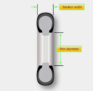
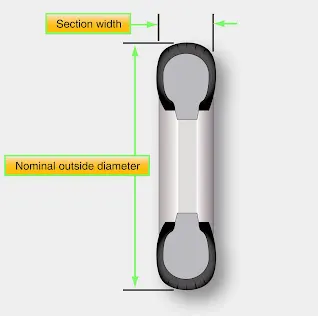
Type III tires are common general aviation tires. They are typically used on light aircraft with landing speeds of 160 miles per hour (mph) or less. Type III tires are relatively low-pressure tires that have small rim diameters when compared to the overall width of the tire. They are designed to cushion and provide flotation from a relatively large footprint. Type III tires are designated with a two number system. The first number is the nominal section width of the tire, and the second number is the diameter of the rim the tire is designed to mount upon.
Type 7:
Type VII tires are high performance tires found on jet aircraft. They are inflated to high-pressure and have exceptional high load carrying capability. The section width of Type VII tires is typically narrower than Type III tires. Identification of Type VII aircraft tires involves a two-number system. An X is used between the two numbers. The first number designates the nominal overall diameter of the tire. The second number designates the section width.
Type 8:
Type VIII aircraft tires are also known as three-part nomenclature tires. [Figure 3] They are inflated to very high-pressure and are used on high-performance jet aircraft. The typical Type VIII tire has relatively low profile and is capable of operating at very high speeds and very high loads. It is the most modern design of all tire types. The three-part nomenclature is a combination of Type III and Type VII nomenclature where the overall tire diameter, section width, and rim diameter are used to identify the tire. The X and “–” symbols are used in the same respective positions in the designator.
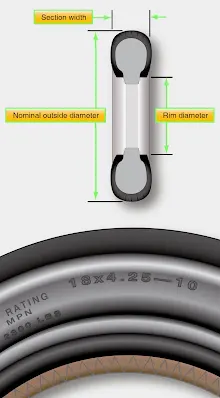
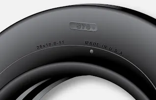
When three part nomenclature is used on a Type VIII tire, dimensions may be represented in inches or in millimeters. Bias tires follow the designation nomenclature and radial tires replace the “–” with the letter R. For example, 30 X 8.8 R 15 designates a Type VIII radial aircraft tire with a 30-inch tire diameter, an 8.8-inch section width to be mounted on a 15-inch wheel rim.
Bias ply or radial:
Another means of classifying an aircraft tire is by the direction of the plies used in construction of the tire, either bias or radial. Traditional aircraft tires are bias ply tires. The plies are wrapped to form the tire and give it strength. The angle of the plies in relation to the direction of rotation of the tire varies between 30° and 60°. In this manner, the plies have the bias of the fabric from which they are constructed facing the direction of rotation and across the tire. Hence, they are called bias tires. The result is flexibility as the sidewall can flex with the fabric plies laid on the bias.
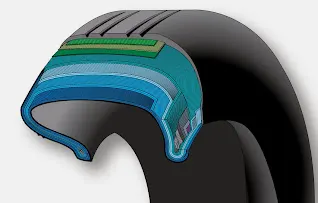
some modern aircraft tires are radial tires. The plies in radial tires are laid at a 90° angle to the direction of rotation of the tire. This configuration puts the non-stretchable fiber of the plies perpendicular to the sidewall and direction of rotation. This creates strength in the tire allowing it to carry high loads with less deformation.
Bead:
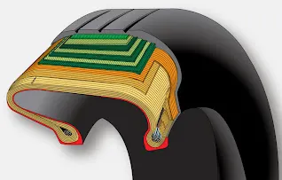
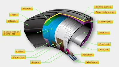
The tire bead is an important part of an aircraft tire. It anchors the tire carcass and provides a dimensioned, firm mounting surface for the tire on the wheel rim. Tire beads are strong. They are typically made from high-strength carbon steel wire bundles encased in rubber. One, two, or three bead bundles may be found on each side of the tire depending on its size and the load it is designed to handle. Radial tires have a single bead bundle on each side of the tire. The bead transfers the impact loads and deflection forces to the wheel rim. The bead toe is closest to the tire centerline and the bead heel fit against the flange of the wheel rim.An apex strip is additional rubber formed around the bead to give a contour for anchoring the ply turn-ups. Layers of fabric and rubber called flippers are placed around the beads to insulate the carcass from the beads and improve tire durability. Chafers are also used in this area. Chafer strips made of fabric or rubber are laid over the outer carcass plies after the plies are wrapped around the beads. The chafers protect the carcass from damage during mounting and demounting of the tire. They also help reduce the effects of wear and chafing between the wheel rim and the tire bead especially during dynamic operations.
Carcass Plies:
Carcass plies, or casing plies as they are sometimes called, are used to form the tire. Each ply consists of fabric, usually nylon, sandwiched between two layers of rubber. The plies are applied in layers to give the tire strength and form the carcass body of the tire. The ends of each ply are anchored by wrapping them around the bead on both sides of the tire to form the ply turn-ups. As mentioned, the angle of the fiber in the ply is manipulated to create a bias tire or radial tire as desired. Typically, radial tires require fewer plies than bias tires.Once the plies are in place, bias tires and radial tires each have their own type of protective layers on top of the plies but under the tread of the running surface of the tire. On bias tires, these single or multiple layers of nylon and rubbers are called tread reinforcing plies. On radial tires, an undertread and a protector ply do the same job. These additional plies stabilize and strengthen the crown area of the tire. They reduce tread distortion under load and increase stability of the tire at high speeds. The reinforcing plies and protector plies also help resist puncture and cutting while protecting the carcass body of the tire.
Tread:
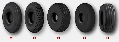
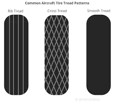
The tread is the crown area of the tire designed to come in contact with the ground. It is a rubber compound formulated to resist wear, abrasion, cutting, and cracking. It also is made to resist heat build-up. Most modern aircraft tire tread is formed with circumferential grooves that create tire ribs. The grooves provide cooling and help channel water from under the tire in wet conditions to increase adhesion to the ground surface. Tires designed for aircraft frequently operated from unpaved surfaces may have some type of cross-tread pattern. Older aircraft without brakes or brakes designed only to aid in taxi may not have any grooves in the tread. An all-weather tread may be found on some aircraft tires. This tread has typical circumferential ribs in the center of the tire with a diamond patterned cross tread at the edge of the tire.The tread is designed to stabilize the aircraft on the operating surface and wears with use. Many aircraft tires are designed with protective undertread layers as described above. Extra tread reinforcement is sometimes accomplished with breakers. These are layers of nylon cord fabric under the tread that strengthen the tread while protecting the carcass plies. Tires with reinforced tread are often designed to be re-treaded and used again once the tread has worn beyond limits. Consult the tire manufacturer’s data for acceptable tread wear and re-tread capability for a particular tire.
Sidewall:
The sidewall of an aircraft tire is a layer of rubber designed to protect the carcass plies. It may contain compounds designed to resist the negative effects of ozone on the tire. It also is the area where information about the tire is contained. The tire sidewall imparts little strength to the cord body. Its main function is protection.The inner sidewall of a tire is covered by the tire inner liner. A tube-type tire has a thin rubber liner adhered to the inner surface to prevent the tube from chafing on the carcass plies. Tubeless tires are lined with a thicker, less permeable rubber. This replaces the tube and contains the nitrogen or inflation air within the tire and keeps from seeping through the carcass plies.The inner liner does not contain 100 percent of the inflation gas. Small amounts of nitrogen or air seep through the liner into the carcass plies. This seepage is released through vent holes in the lower outer sidewall of the tires. These are typically marked with a green or white dot of paint and must be kept unobstructed. Gas trapped in the plies could expand with temperature changes and cause separation of the plies, thus weakening the tire leading to tire failure. Tube-type tires also have seepage holes in the sidewall to allow air trapped between the tube and the tire to escape.
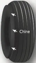
Chine:
Some tire sidewalls are mounded to form a chine. A chine is a special built-in deflector used on nose wheels of certain aircraft, usually those with fuselage mounted engines. The chine diverts runway water to the side and away from the intake of the engines.Tires with a chine on both sidewalls are produced for aircraft with a single nose wheel.
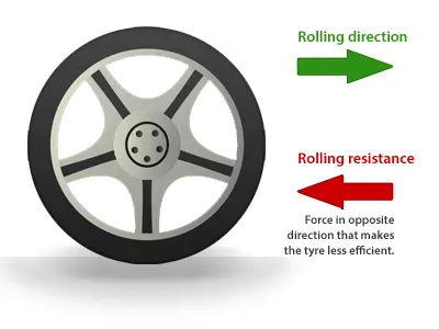
Rolling resistance of tire:
Choosing tyre materials and construction that don't heat up as much will result in less rolling resistance.
Calculating rolling resistance
This equation is used to calculate the force of rolling resistance from each tyre:
FRR = CRR x weight
FRR is the rolling resistance force.
CRR is the coefficient of rolling resistance (a number used to rate each tyre at a given pressure). weight is the force due to gravity being exerted on each tyre (= mass (kilograms) x 9.8).
This equation shows that speed does not affect the force due to rolling resistance. The type of tyre and the mass of the bike plus rider are the only two variables.
Tire pressure:
An aircraft tire or tyre is designed to withstand extremely heavy loads for short durations. The number of tires required for aircraft increases with the weight of the aircraft, as the weight of the airplane needs to be distributed more evenly. Aircraft tire tread patterns are designed to facilitate stability in high crosswind conditions, to channel water away to prevent hydroplaning, and for braking effect.Aircraft tires also include fusible plugs (which are assembled on the inside of the wheels), designed to melt at a certain temperature. Tires often overheat if maximum braking is applied during an aborted takeoff or an emergency landing. The fuses provide a safer failure mode that prevents tire explosions by deflating in a controlled manner, thus minimizing damage to aircraft and objects in the surrounding environment.
Inflation:
Each of the twelve Boeing 777-300ER main tires is inflated to 220 psi (15 bar; 1,500 kPa), weighs 120 kg (260 lb), has a diameter of 134 cm (53 in) and is changed every 300 cycles while the brakes are changed every 2000 cycles.Aircraft tires generally operate at high pressures, Inflation up to 200 psi (14 bar; 1,400 kPa) for airliners, and even higher for business jets.Tests of airliner aircraft tires have shown that they are able to sustain pressures of maximum 800 psi (55 bar; 5,500 kPa) before bursting.Aircraft tires are usually inflated with nitrogen to minimize expansion and contraction from extreme changes in ambient temperature and pressure experienced during flight.
Brake forces when landing:
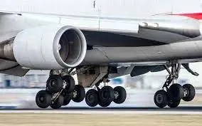
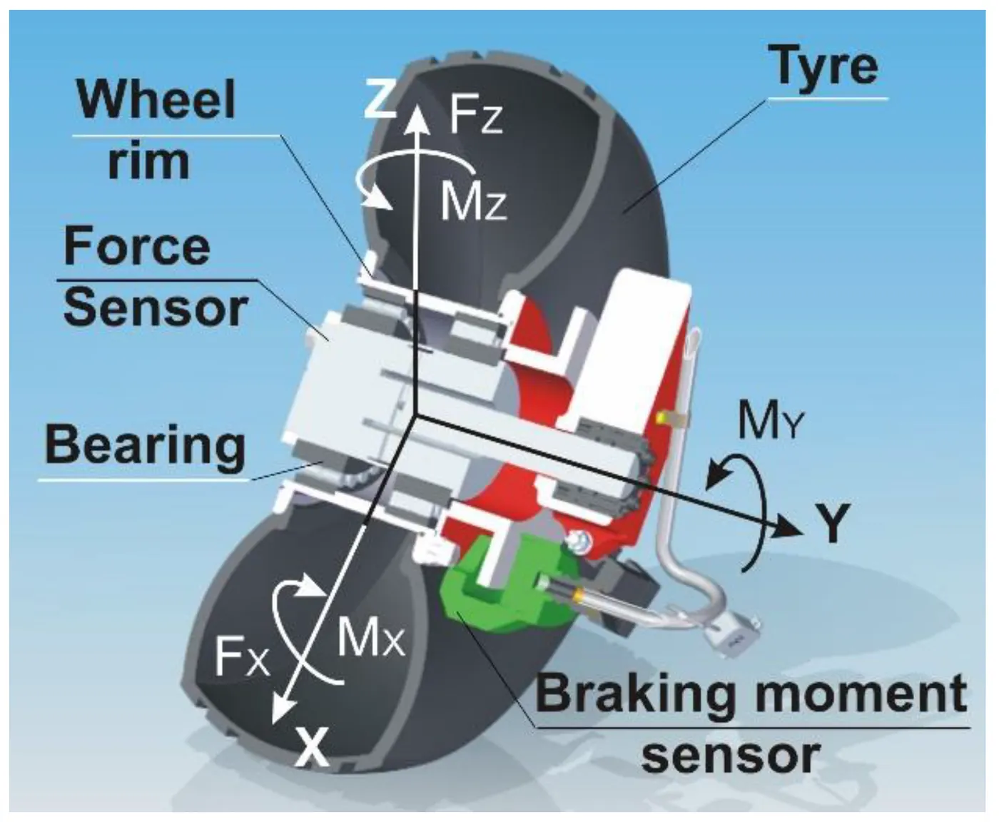
Airplanes rely on a braking system to safely land on runways. At cruising altitude, most commercial airplanes fly at a speed of roughly 500 to 600 mph. When landing, however, they must reduce their speed. A typical 747, for instance, has a landing speed of about 160 to 170 mph. And upon touching the runway, airplanes must quickly brake until they come to a complete stop.
- Wing spoilers:
Many airplanes use wing spoilers to assist with braking when landing. Not to be confused with ailerons, spoilers are extendable flaps on the ends of an airplane’s wings. Pilots can raise the spoilers to decelerate the airplane as it approaches the runway. And even while on the runway, pilots will typically leave the wing spoilers raised. Raised wing spoilers create drag, which essentially slows down the airplane so that it’s able to brake more quickly.
- Disc brakes:
In addition to wing spoilers, airplanes use disc brakes. Airplane disc brakes are similar to the braking system in automobiles. They consist of a pair of calipers that, when engaged, squeeze pads against the rotors of an airplane’s landing gear.Disc brakes are designed to remain static at all times. In other words, they don’t rotate with the wheels of an airplane’s landing gear. As the wheels turn, the disc brakes will remain static and stationary. They are a vital component of an airplane’s braking system because they are designed to apply pressure to the airplane’s wheels. Disc brakes will squeeze the wheels, thereby slowing down the speed at which they spin. In turn, this reduces the speed of the airplane so that it can come to a complete stop on the runway.
- Reverse thrust:
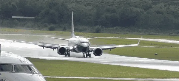
Finally, many jet airplanes use reverse thrust to assist with braking during landings. Reverse thrust is a feature in jet engine airplanes that, as the name suggests, involves the reversal of the engines’ thrust. When flying, the thrust is projected out the rear of an airplane’s engines. When landing, however, pilots may use the reverse thrust feature. Reverse thrust changes the direction of the engines’ thrust. Rather than projecting out the rear, the thrust will be projected out the front. This reversal of thrust provides deceleration that allows airplanes to slow down more quickly when landing.
Part B:
6) A. With necessary assumptions, calculate the force and power required to push / pull an aircraft by a towing vehicle.
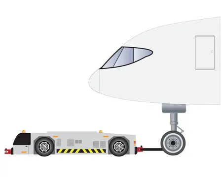
We have to calculate the force and power required to push/pull an aircraft by a towing vehicle:
Lets consider the following parameters of both the aircraft and towing vehicle:
| Airbus - A318(Aircraft) | TBL280(Towing vehicle) |
= 0.02*59000*9.8 = 11564 N
= 0.5*1.225*500.14*0.0235*`8.89^2` = 568.94 N |
= 0.02*35000*9.8 = 6860N
= 0.5*1.225*6.8*0.6*`8.89^2` = 197.5 N |
Total tractive force of aircraft = Frr + Fad = 12132.84 N
Total tractive force of towing vehicle = Frr + Fad = 7057.5 N
Total Tractive Force = 12132.84 + 7057.5
= 19190.34 N
Total Tractive Power = Tractive Force * velocity
= 170603.01 N
= 170.6 kW
Hence total tractive power required to push/pull the aircraft by towing vehicle is ,Pt = 170.6kW
total tractive force required to push/pull the aircraft by towing vehicle is ,Ft = 19190.34N
B. Develop the model for the calculated force and power using Simulink.
Simulink Model for calculting Force and Power :
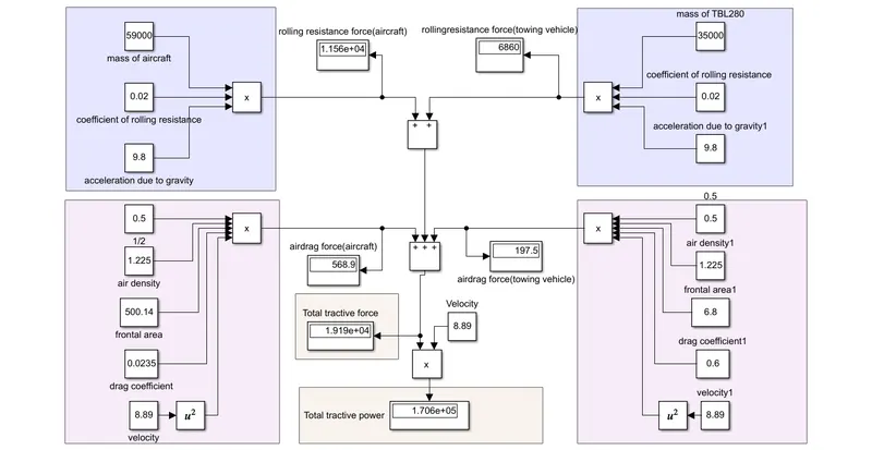
- All the values and parameters are given using the constant block.
- Top left part gives the rolling resistance force of aircraft.And the Top right part gives the rolling resistance part of towing vehicle.
- Bottom left part gives the air drag force of aircraft and bottom right part gives the air drag force of towing vehicle.
- The first adder adds to give the total rolling resistance force
- The second adder adds to give the total air drag force.
- The third adder adds the total rolling resistance force and air drag force to give the Total Tractive force.
- The total tractive force is now multiplied with the velocity which gives the Total Tractive power required to push/pull the aircraft by towing vehicle
The above showed simulink model's .slx file is given below.
7) A. Design an electric powertrain with type of motor, it’s power rating, and energy requirement to fulfill aircraft towing application in Simulink. Estimate the duty cycle range to control the aircraft speed from zero to highest. Make all required assumptions. Prepare a table of assumed parameters. Draw a block diagram of powertrain. (Hint :DC7 Block)
The Energy required to push/pull the aircraft by towing vehicle:
Lets consider the towing process is taking 30minutes of time,that is 0.5 hours or 1800seconds then
Energy,E = Tractive Power `*`time
= 170.6kW `*`30 min
= 170.6 `*`0.5
= 85.3 kWh
Now have to calculate the dutycycle required by the towing vehicle inorder to tow the aircraft ,so weed to first find the input power,
Input Power = Input voltage * Input Current
= 600V*400A
= 240kW
Duty cycle = `(Output power)/(Input Power)`
= `170.6/240`
= 0.7108
= 71.08%
Hence the duty cycle to control the aircraft speed to zero to highest = 71.08%
The following table shows the assumed parameters:
| Airbus - A318(Aircraft) | TBL280(Towing vehicle) |
|
|
Blockdiagram of Powertrain:
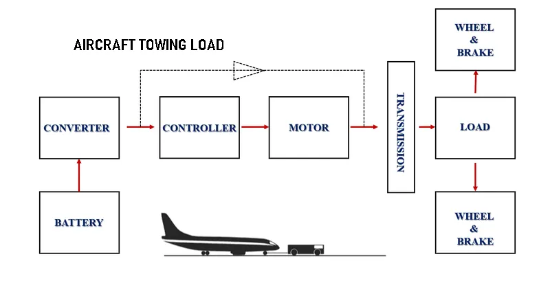
The powertrain blockdiagram is shown above.The battery is to power the powertrain,the converter converts the DC supply from the battery to required output DC voltage and it is fed to the controller which controls the speed and all parameters of the motor and the motor shaft is connected to the transmission system which is connected to the load and wheel and brake system.
Simulink model for an electric powertrain with type of motor,power rating,energy requirement to fulfill aircraft towing application:
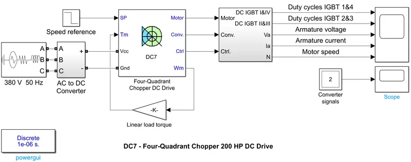
Here the 3phase 380V,50Hz AC supply is converted into the DC supply by using a rectifier.This DC supply is given to the four quadrant chopper as input.Speed reference is also given as an input.In this Four quadrant chopper DC drive the angular speed output is taken and it is multiplied by a gain and converted it to torque and fedback as the torque input.Here the ouput plots we are getting is duty cycles of IGBT 1,2,3,4 ,armature current ,armature voltage,and motor speed.The output plot is shown below:
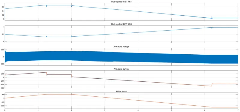
It is clear that as the armature current increases the motor speed also increases and when current decreases the speed also decreases.
B. Also,Design the parameters
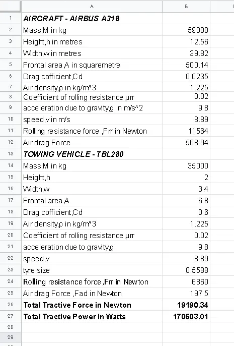
Creating a excel sheet with assumed parameters,
------------------------------------------------------------------------------------------------------------------------------------------------------------------------------------------------------------------------------------------