Week 5 - Rayleigh Taylor Instability
Aim: To perform transient state simulation using a laminar viscous and VOF Multiphase model in ANSYS-FLUENT to understand the Rayleigh Taylor instability phenomena and its different stages of development.
Objectives: The following objectives are accomplished at the end of this literature,
- What are some practical CFD models that have been based on the mathematical analysis of Rayleigh Taylor waves? In your own words, explain how these mathematical models have been adapted for CFD calculations.
- Perform the Rayleigh Taylor instability simulation for 2 different mesh sizes with the base mesh being 0.5 mm. Compare the results by showing the animations( Attach them from your google drive). Observe the differences in the animation and explain the effect of mesh size on simulation. Also, explain why a steady-state approach might not be suitable for these types of simulations.[ Choose Air and Water for this simulation]
- Run one more simulation with water and user-defined material(density = 400 kg/m3, viscosity = 0.001 kg/m-s) for refined mesh.
- Define the Atwood Number. Find out the Atwood number for both the cases and explain how the variation in Atwood number in the above two cases affects the behavior of the instability.
Introduction and Theory
The term Rayleigh Taylor instability was coined after two scientists (Lord Rayleigh and G I Taylor) who studied the behavior of two immiscible fluids placed one above the other. The dense fluid placed at the top and the less dense fluids at the bottom. Under the gravitational field effect, the less dense fluid will be displaced upwards and the denser fluid will be displaced downwards.
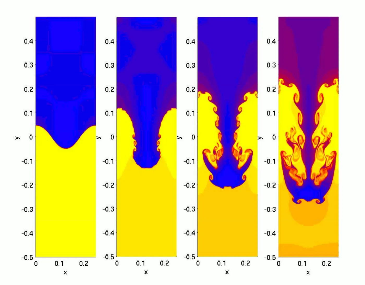
The water atop oil is an everyday example of Rayleigh-Taylor instability. It may be modeled by two completely plane-parallel layers of immiscible fluids, the denser on the top of less dense both are subjected to earth's gravitational field. The equilibrium is unstable to any disturbances of the interface. The disturbances increase with time as the denser fluid continues to move down and the less dense fluid continues to move up.
As the RT instability develops the initial disturbances progress from a linear to nonlinear phase growth eventually developing plumes flowing upwards and spikes moving downwards. In the linear phase, the fluid movement can be approximated with a linear equation, in the nonlinear phase the disturbances grow exponentially with time making it very difficult to calculate it linearly, thus the nonlinear equation comes into play. In general, the disparity in density value determines the structure of the nonlinear RT instability flows.
CFD models based on RT instability analysis
- Modeling spray atomization with the Kelvin-Helmholtz/Rayleigh-Taylor hybrid model: An improved spray atomization model is presented in both diesel and gasoline spray computation. It consists of two steps primary and secondary breakup. The KH instability model is used to predict the primary breakup of the intact liquid core of a diesel jet. The secondary breakup was modeled with the KH model in conjunction with the RT instability model.
- Modeling of RT instability for stream direct contact condensation: As per the RT instability theory, leading to the breakup of the surface and triggering steam depressurization typical of chugging phenomena, since the phenomena of chugging introduce large water mixing at the onset of every water discharge cycle.
- Cold Plumes initiated by RT instabilities in Subduction Zones, and their characteristics volcanic Distributions: The role of Slab Dip: Dehydration melting in subduction zones often produces cold plumes initiated by RT instabilities in the buoyant partially molten zones lying above the dipping subduction slabs.
- A lattice Boltzmann scheme for incompressible multiphase flow and its application in simulation of RT instability: The scheme simulates fluid flows based on distribution functions. The interfacial dynamics, such as phase segregation and surface tension, are modeled by incorporating molecular interactions. The numerical stability is improved by reducing the effect of numerical errors in the calculation of molecular interaction.
Application of RT instability
RT instability plays an important role in the formation of astrophysical structures like in the supernova remnants in the Eagle and Crab nebulae as well as in many industrial processes. It is also important in inertial confinement fusion as it determines the minimum energy required for ignition and in the design of nuclear weapons.
Solving and Modeling approach
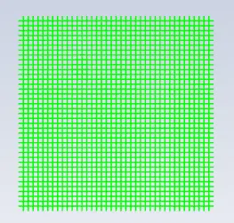
The computational domain for simulating the RT instability and loaded into Spaceclaim. The individual sub-domain was created with each surface measuring `20mm**20mm` sharing the common interface. This is possible by drawing the subdomains into the same plane and stretching the other domain into the same plane.
The Spaceclaim provides an option of "Pull" in its ribbon. By selecting the pull icon the selected geometry is turned into a surface. Thus each geometry having a common interface is selected and the surface is created.
The two interfaces must share the information to have a conformal mesh. Sharing icon is selected under Workbench. It would offer negligible to minimum interpolation at the interface, reducing computational time and rendering accuracy to the solution.
Preprocessing and solver setting
Baseline mesh
The geometry is prepared in the SpaceClaim.
The rectangle of dimension (`20mm` `**` `20mm)` is made one above the other. The lower rectangle will represent air and the upper rectangle will represent water.
The pull option present in the ribbon is selected after drawing each geometry to convert it into a surface.
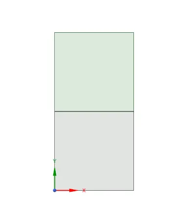
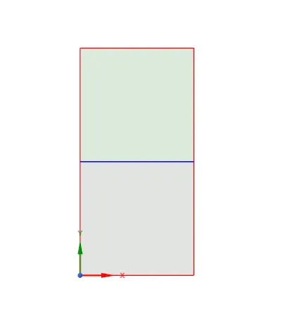
Share topology
The share topology is created such that the mesh from two surfaces shares information from each other.
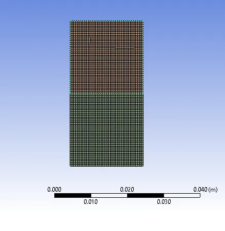
Meshing: It is the process of discretization of geometry into a small number of volumes containing nodes using a finite volume method scheme.
Solver setting
- The surface representing water is selected.
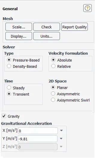
General settings
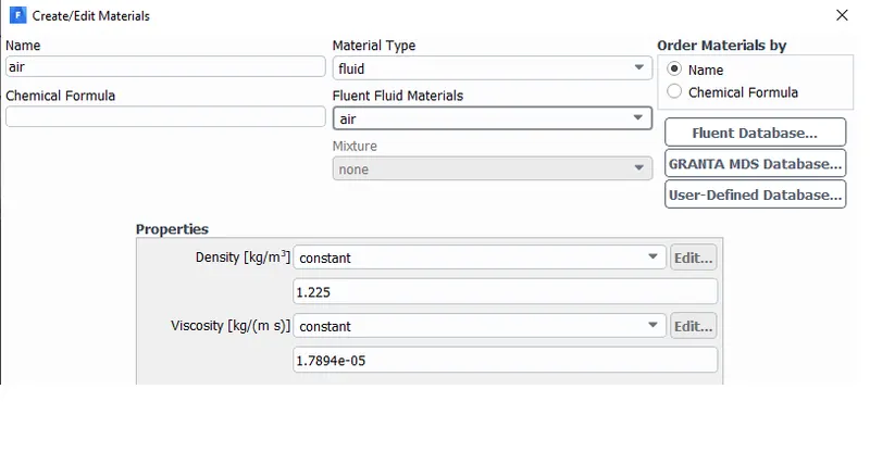
Material property
Air
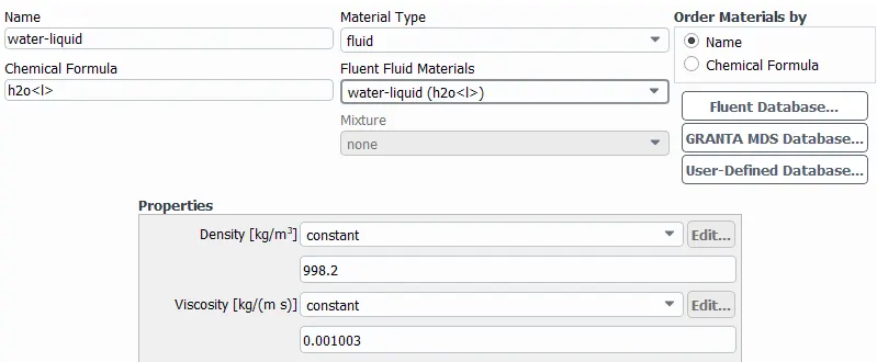
Water
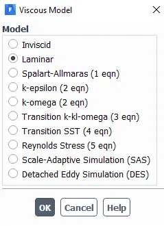
Viscous model
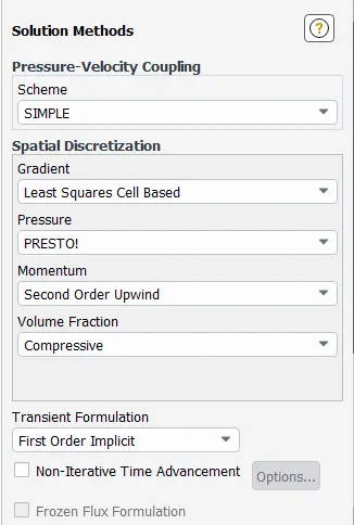
Solution methods
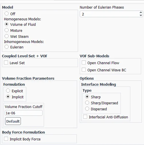
Multiphase modeling
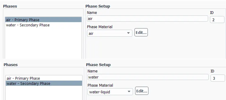
Phases
Standard initialization is selected.
The solution is initialized by hitting `t` `=` `0`.
The patch is created for tracking the different values of flow variables into different cells.
The volume fraction is selected which represents the space occupied by each phase. The tracking of phase is done by solving the continuity equation for the volume fraction of one or more phases.
The water phase has been assigned a value of 1 and the air phase has been assigned a value of 0.
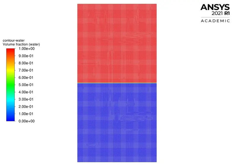
The contour plot is created for the water phase. The contour plot depicting the initial boundary condition is shown below
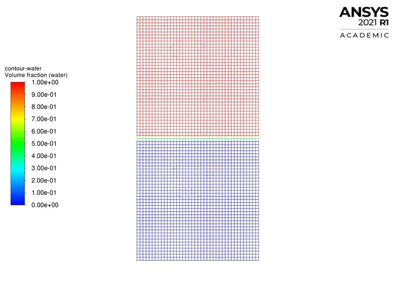
The top surface contains a water phase and the bottom face has an air phase which brings us to the conclusion that the patch has been created successfully.
The animation is created for the contour water to observe the changes in the flow pattern at different time steps.
Run calculation
Number of iteration: `1000`
Time step size : `0.005` `s`
Maximum iteration/ time step : `20`
Results
Residual plot
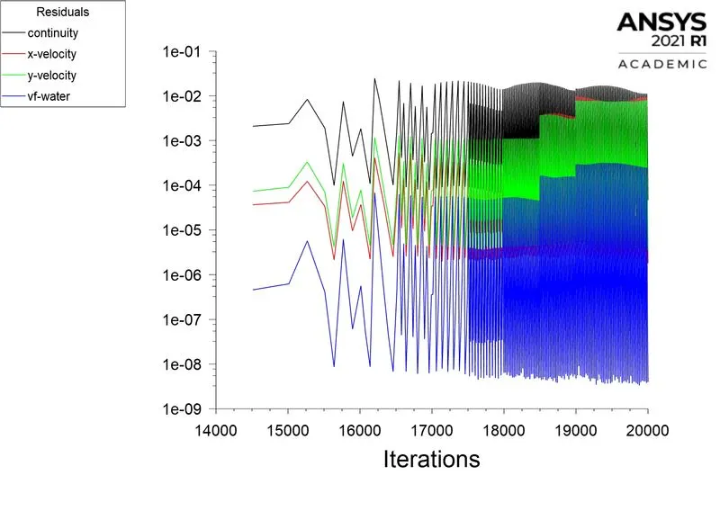
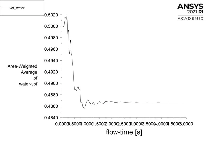
VOF_water=`0.486718`
VOF_water contour animation for element size `0.5mm`
Refined mesh
Element size: `0.1mm`
Number of elements: `80000`
Number of nodes: `80601`
Initial VOF_water contour
Results
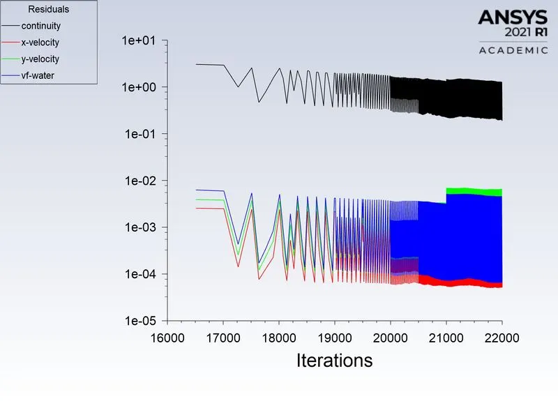
Residual plot
VOF_water plot
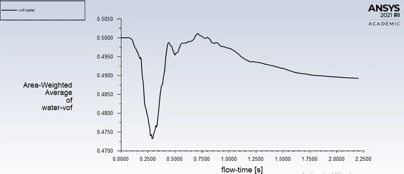
VOF_water=`0.4892575`
Refined mesh with user-defined material.
Element size: `0.1mm`
Number of elements: `80000`
Number of nodes: `80601`
User-defined material density `rho=400frac{kg}{m^3}`
User-defined viscosity `mu=0.001frac{kg}{m-sec}`
Residual plot
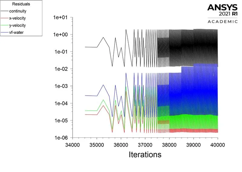
VOF_water plot
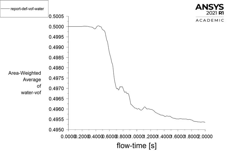
VOF_water=`0.4953473`
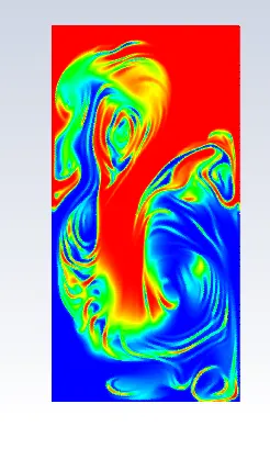
VOF_water contour animation for element size `0.1mm`
Stages in RT instability analysis for the refined mesh
- Initial disturbances
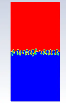
- Formation of bubbles
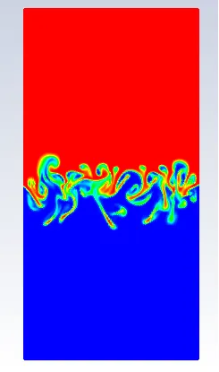
- Formation of spikes
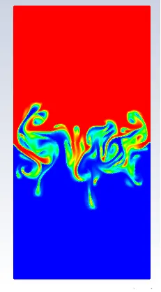
- The onset of turbulent mixing
Atwood number: The Atwood number (A) is a dimensionless number in fluid dynamics used in the study of hydrodynamic instabilities in density stratified flows. It is a dimensionless density ratio defined as
`A=frac{(rho_1-rho_2)}{(rho_1+rho_2)}`
where
`rho_1``=` density of the heavier fluid.
`rho_2``=` density of the lighter fluid.
Field of application
It is used in RT instability analysis. The penetration distance of heavier fluid into the lighter fluid is a function of acceleration time scale, `Ag t^2` where g is the gravitational acceleration and t is the time.
Atwood number for multiphase flow involving water and air
`A=frac{(rho_1-rho_2)}{(rho_1+rho_2)}``=` `0.9975`
Atwood number for multiphase flow involving water and user-defined material
`A=frac{(rho_1-rho_2)}{(rho_1+rho_2)}``=` `0.4278`
Mesh statistics and volume of fraction water values
| Element size | Number of elements | Number of nodes | VOF_water | Atwood number | ||
| Water and air | Water and user-defined material | Water and air | Water and user-defined material | |||
| `0.5mm` | `3200` | `3321` | `0.486718` | N/A | `0.9975` | `0.4278` |
| `0.1mm` | `80000` | `80601` | `0.4892575` | `0.4953473` | ||
Conclusion
- The numerical analysis of the RT instability for (water+air) and (water+user defined material) under transient conditions and using the laminar viscous model was well understood.
- The implicit time scaling method is followed for the simulation as it is unconditionally stable.
- For the second case where `A=0.4278` the density difference between the two sides of the interface is small, and the density distribution of the upper and lower layer is nearly symmetrical. The initial density stratification plays a dominant role, and the expansion compression effect has little influence.
- For the first case where `A=0.9975` the stabilization effect of initial density stratification decreases and the instability caused by the expansion-compression effect becomes more significant. The effect of compressibility on the bubble velocity is strong at large Atwood number.
- The initial disturbances, formation of bubbles, spikes formation in the bubbles, the onset of turbulent mixing were well observed for the finer mesh.
- The penetration distance is given by `Ag t^2` thus air will be having more penetration distance than the user-defined material.
- The accuracy of the solution can be improved by the reduction in time step size.
- The steady-state simulation was not carried for the RT instability analysis because we are not concerned with the end results, the disturbances in RT analysis is time-dependent so transient simulation is preferred.