Week 5.2 - Multi Level Meshing
Aim: To create a non-conformal meshing for the given Icepak object and comment on the quality of the mesh.
Introduction:
The given Icepak model is a CAD model consists of three assemblies namely Sheet metal heat sink assembly, DIMM's assembly, and a fan guide assembly. Two grilles are attached on adjacent sides as shown in Fig. 1 and the expanded view is shown in Fig. 2. A non-conformal mesh has to be created for the given model and reduce the mesh count again by creating a non-conformal mesh by refining the mesh using multi-level meshing and uniform mesh parameters. The work is to create a non-conformal mesh with not more than 500,000 mesh counts.
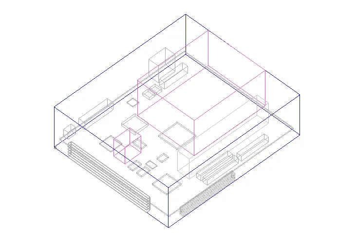
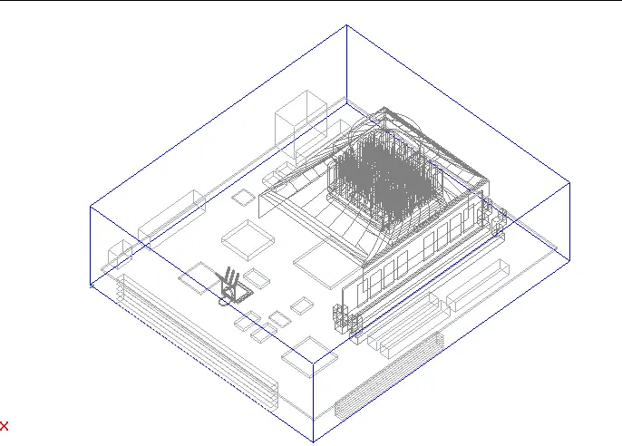
Fig. 2 Expanded view of the Icepak model
Procedure
Step 1
Automatic case check tool.
Firstly, the initial inspection is done to make sure that there are no assembly intersection or thin conducting plate and assembly interaction as shown in Fig. 3
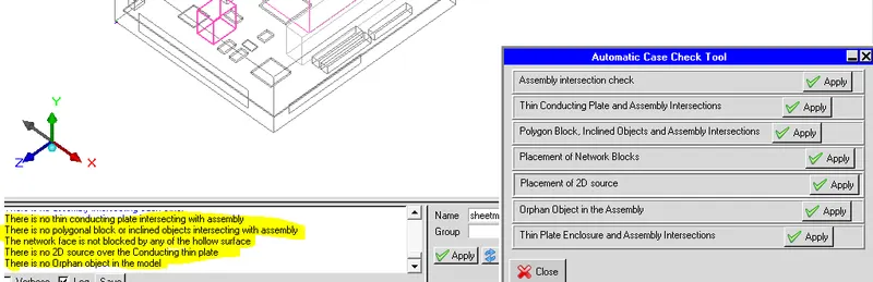 Fig. 3 Case check
Step 2
1. A non-conformal mesh has been created without using the multi-level meshing and uniform object parameters. The number of elements is found to be around 0.7 million
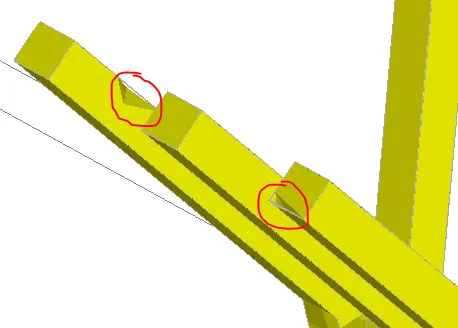
Fig. 4. The meshing of the CAD object
2. The mesh is observed around the CAD object. It shows that the CAD objected is not properly meshed Which is shown in Fig. 4
3. Also another CAD object has not meshed properly and is shown in Fig. 5
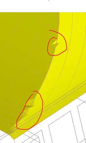
Fig. 5. Meshing Guide sweep object.
The quality (Face alignment, Volume, and skewness) of the mesh is shown in Fig. 6, 7, and 8 respectively
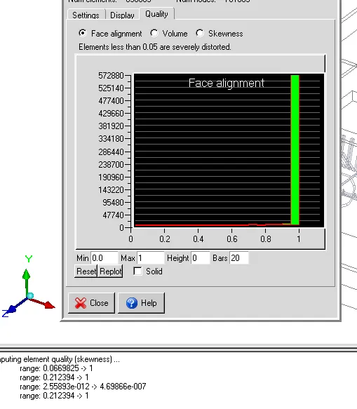 Fig. 6 Face alignment Quality
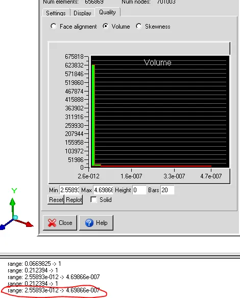 Fig. 7 Volume quality
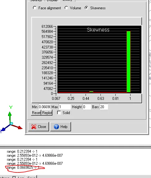 Fig. 8 Skewness quality
Step 3
Referring to the above cases, it is observed that the CAD objects have not meshed properly. Hence, multi-level is suggested.
The values for multi-level meshing is entered by right-clicking the assembly option, edit and then in the meshing tab, under multi-level settings, the allow multi-level settings are turned on, and the maximum level is set to 2 as shown in Fig. 9
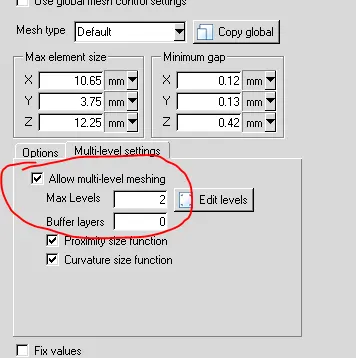
Fig. 9. Multi-level meshing
Then, in the options tab, the use average option is used as shown in Fig. 10
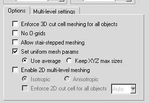
Fig. 10 Use average for set uniform mesh parameters
With the above two settings, the mesh is generated and the mesh count was found to be around 1 million elements, and the improvement in meshing is shown in Figures 11 and 12 respectively.
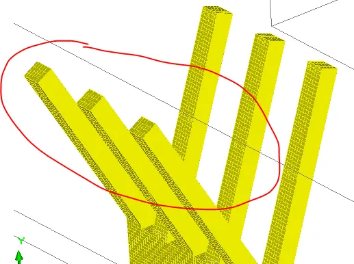
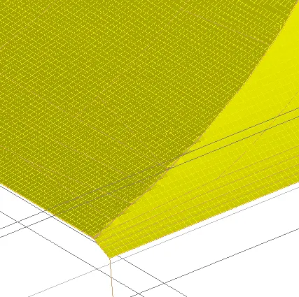
Fig. 11 Sheet metal mesh improvement Fig. 12 Guide sweep mesh improvement
The quality of the mesh is seen through the cut plane on both the cad objects and is shown in Fig 13 and 14 respectively.
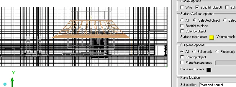
Fig. 13 Mesh around CAD object 1
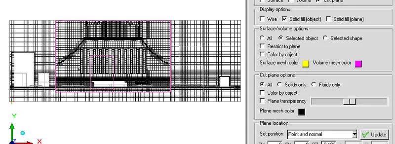
Fig. 14 Mesh around CAD object 2
By careful observation of the mesh, using multi-level meshing, the quality of the meshing of the CAD object has improved but with increased mesh count.
The quality of the mesh for face alignment, volume, and skewness after multi-level meshing settings shown in figures 15, 16, and 17 respectively.
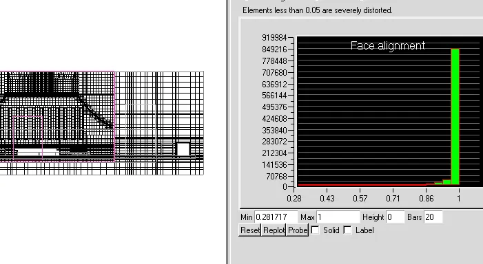 Fig. 15. Face alignment quality
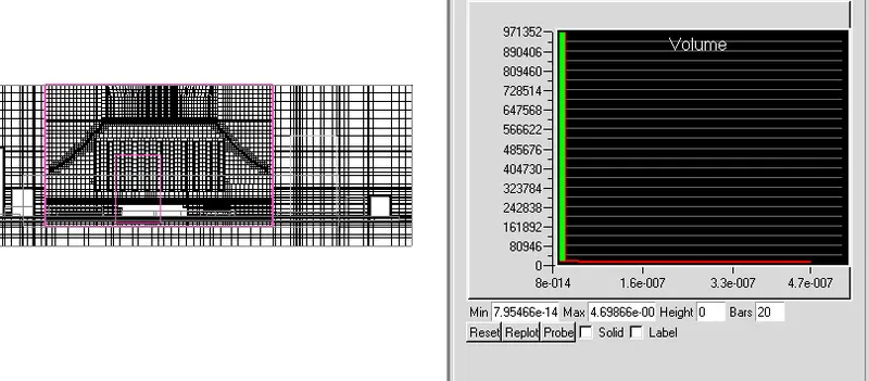 Fig. 16 Volume quality
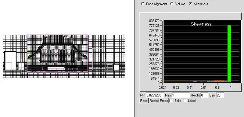 Fig. 17 Skewness quality
Result.
The quaity of the mesh for CAD objects is not of a good quality (even with the Normal mesh) as it is seen in the above figures. Hence multi-level meshing plays a vital role in discritizing the CAD objects in an effective way . This helps in improving the quality of the mesh.