Week 6.1 - Setting up a model (Electronic enclosure)
Aim: To conduct a steady state analysis for the given electronic enclosure under natural convection
Introduction: The assembly contains many components such as resistors, capacitors, heat conductors, heat sink, grilles, power house, USB ports and many more. The power house supplies a heat of 20 W and the working of all other component generates heat which will be dissipated by the heat sink.
Procedure: The given electronic enclosure is simplified in space claim as per the procedure explained below
Step 1: Simplifying the geometry
The problem is setup and is shown in Fig. 1. 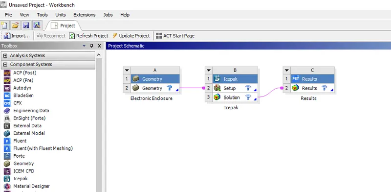
Using the split body command in the Design Menu, the given object is splitted and the geometries which doesnot affect the flow is removed and is shown in Fig. 2. and Fig. 3. also, the unnecessary screws and washers are also removed.
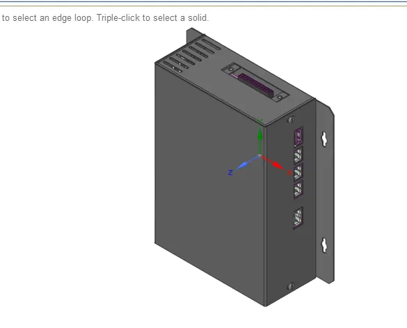
Fig. 2
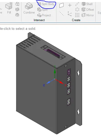
Fig. 3
After removing the top cover, screws and washers, the CAD object is shown in Fig. 4. This object is further simplified for the analysis.
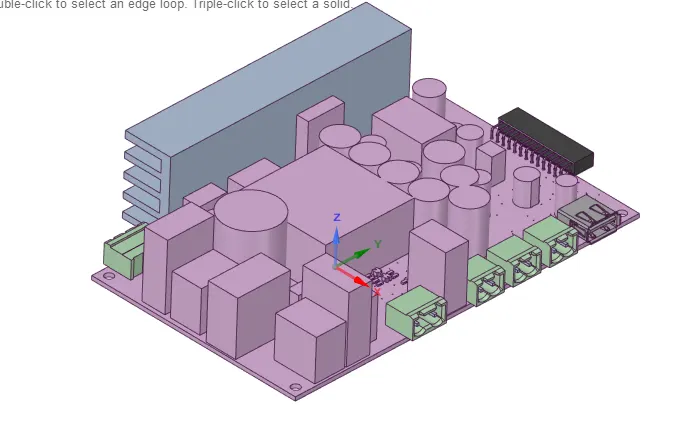
Fig. 4
After splitting the power box assembly, the icepak objects are identified in the Workbench menu as shown in Fig. 5
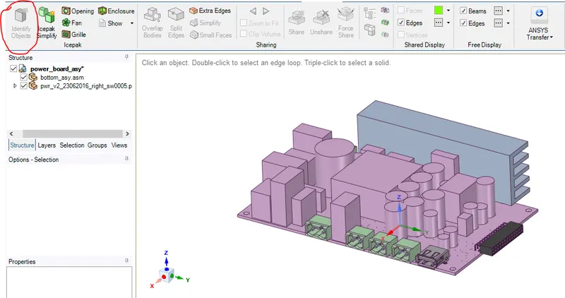
Fig. 5
The remaining objects will be simplified using icepak simplify in the same menu and is shown in Fig. 6
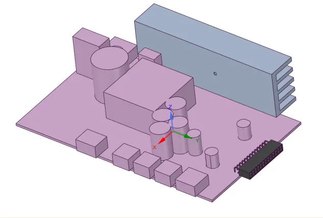
Fig. 6
The bottom board, USB port, Power port and other network ports are simplified using Level 0.
Some of the components are attached to each other. They cannot be simplified as it is. Hence, it is splitted first and the components are simplified there after.
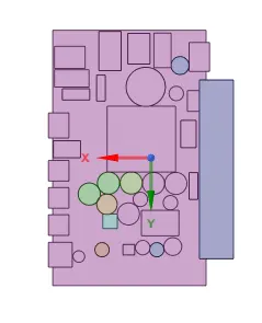
Fig. 7
Fig. 7 shows the icepak simplified objects. Careful observation shows that some of the components are attached to each other. Hence, the objects are slightly moved using Move command in Design menu.
Fig. 8 shows the Simplified final CAD object.
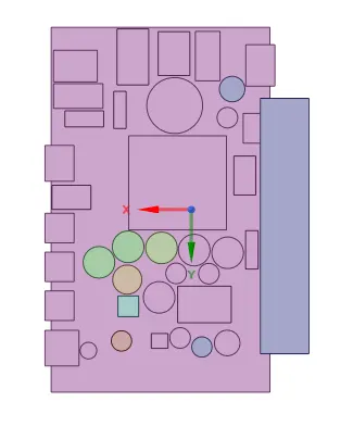
Fig. 8
Step 2: Meshing and solving in ICEPAK
Grilles are added on the two faces in Min and Max Y direction. Also an opening is given for the Min x direction as shown in Fig. 9
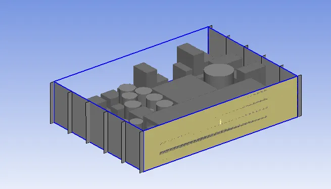
Fig. 9
The objects close to heat sink is given a power input of 10 W and the power source is given a heat input of 20 W. as shown in Fig. 10
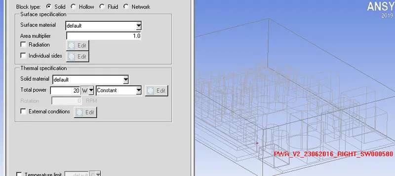
Fig. 10
After meshing, the number of elements were close to 0.4 million were generated as shown in Fig 11.
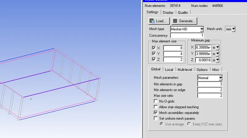
Fig. 11
Steady state negligible radiation and with zero equation turbulence model is used to solve the problem as shown in Fig. 12
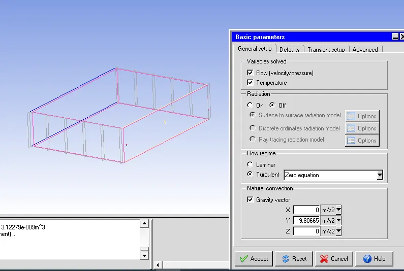
Fig. 12
Step 3: Results and Discussion
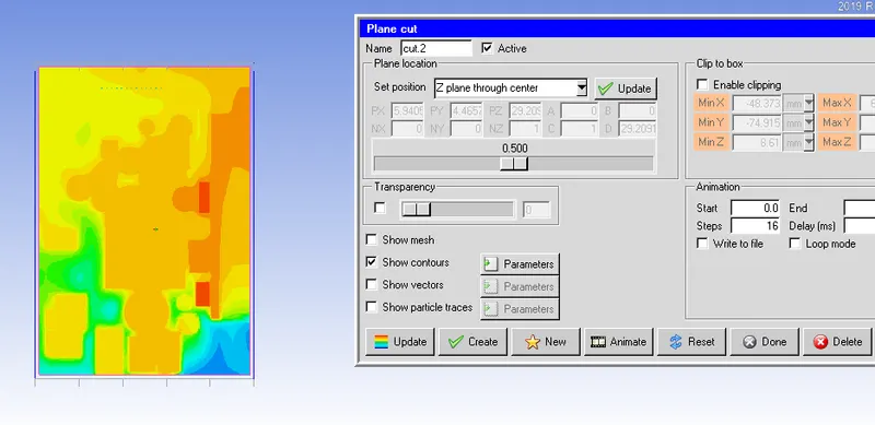
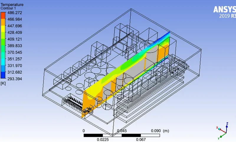
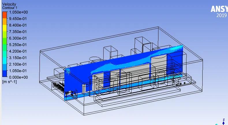
The given problem is analysed for natural convection condition using Boussinesq approximation. Following figures 13 show the temperature, velocity contours respectively.
Temperature contour
Velocity contour
From the temeprature contour, it is clear that the Maximum temperature for the gien flow conditions is found to be 486 K and it is found in an object near the heat sink.
Fig. 13
Fig, 14 and Fig. 15 show the temperature contour of the board and heat sink respectively.

Fig. 14
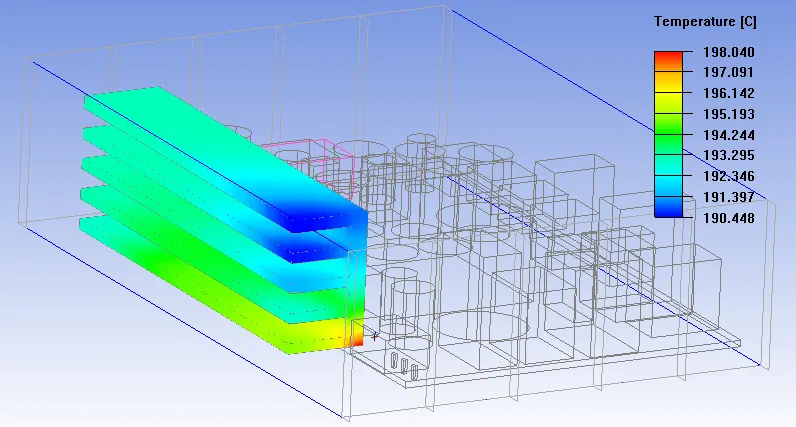
Fig. 15
Conclusion
The given problem is analysed under natural convection and following points were observed.
1. Due to less availability of space, the air movement is difficult because of which the temperature is in the electronic assembly is high. The size of the electronic cabinet need to increased marginally in order to increase the air flow rate in the board.
2. More area is required for heat sink so as to keep its temperature lower than the present value.