Week 7 - Mid-term Project - Natural Convection
Aim: To create a non conformal assembly of the given voltage panel and investigate the temperature rise for natural convection condition.
Introduction:
Electrical Control Panel:
Electrical control panel is a CRCA(cold rolled close annealed) ms sheet enclosure that contains electrical switchgear that controls and monitors a mechanical process electrically.
In process plant one or more motor control by a piece of equipment that called an electrical control panel. The electrical control panel starts or stops many equipment's through switchgear and SCADA automation by using MCCB, Contractor, PLC, Overload relay and plug-in relay, etc.
There are three types of electrical control panels.
-
Power control center (PCC Panel)
-
Motor Control center (MCC Panel)
-
Automation Panel (SCADA PLC Panel)
1. PCC Panel:
Fig. 1 shows PCC Panel that contains all of the electrical switchgear like an air circuit breaker, MCC's, mcb, and suitable size aluminum or copper busbar. The main circuit breaker is where the power comes into the control panel for all of the switchgear. This circuit breaker generally has an isolate on the panel that allows us to shut off the power. The power that comes into the panel can be anywhere from 440 volts to 800V AC.
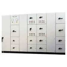 Fig. 1 PCC Panel
2. MCC Panel
Fig. 2 shows an MCC panel. In many commercial and Industry applications, multiple electric motors are required, and it is often desirable to control some of the motors. The apparatus designed for this type of function is the Motor Control Center Panel (MCC Panel).
When a motor operation runs with the protection of overload relays or solid-state motor controllers. An MCC Panel manufacturer has a control from a remote or local that is called a motor control panel. There are combinations of different types of starters like direct online (DOL) Starter or star-delta starter.
MCC Panel (motor control center) is used for motor control of various electrical power Industries. Therefore, it is most important in electricity. MCC panel is an Electrical control panel in LT panels. In other words, it can control the motor from generation to production.
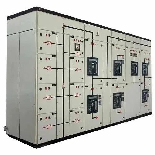 Fig. 2 MCC Panel
3. Automation panel (SCADA PLC Panel)
Fig. 3 shows SCADA and PLC panel. Automation panel (Scada PLC panel) is a Programmable digital computer also known as PLC Automation Panel is one of the most important and efficient kinds of control panels. Which are generally used in a variety of electronic and electrical circuit fittings. Integrated with solid PLC logic and flawless PLC hardware programming.
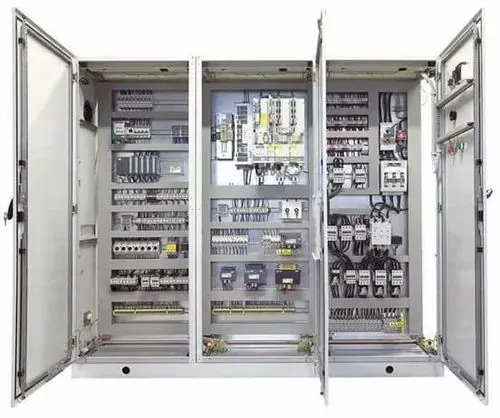
Fig. 3. SCADA and PLC Panel
Procedure:
Step 1. Create cabinet and enclosure of the given dimensions. For convenience, the size of the cabinet and the enclosure are changed.
The cabinet and enclosure dimensions in mm are given table 1below
Table 1. Cabinet and encosure dimensions
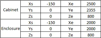
The grilles are positioned on the enclosure. The bus bars are created from the dimensions as per the dimensions given in the table. 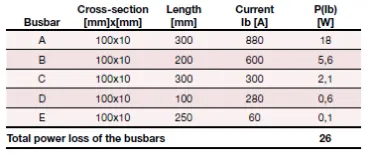
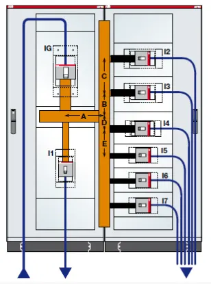
Since, liberty is given to chose to circuit breakers dimension and its position, hence the circuit breakers are created and positioned to look like the panel sketch as shown below. The circuit breakers and bus bars material are chosen to be copper pure and the surface material is chosen to be copper polished surface.
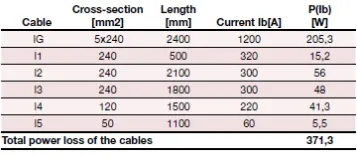
Similarly, the cables are also created as per the dimensions given in the table.
The front view, side view and isometric view of the final model is shown in Fig. 4a, 4b and 4c respectively.
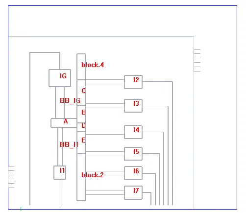 Fig. 4a
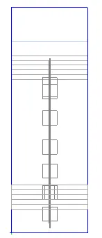 Fig. 4b
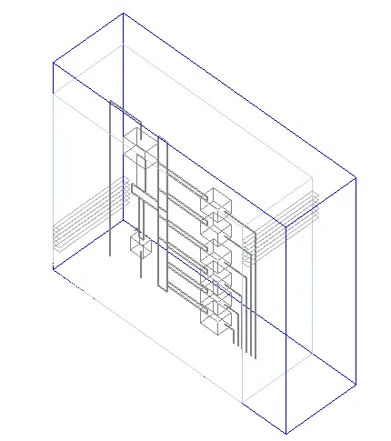 Fig. 4c
Step 2:
Mention the power loss values
As per the values given in the table 7.8 and 7.9 in the problem statement, the power loss values are specified for the circuit breakers and the bus bars.
Step 3. Meshing
An assembly is created combining all the blocks (Includes all cables, CB's and BB's). A slack of 5 mm is given in all directions as shown in Fig. 5
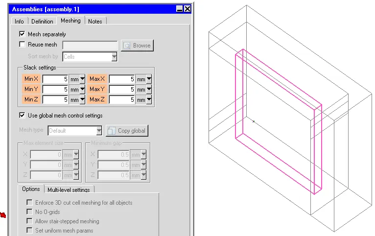
Fig. 5 Slack values for the assembly
Normal Mesh is generated which resulted in 372008 elements.
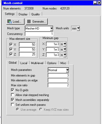
Fig. 6a,6b and 6c shows the mesh in Z plane, X plane and Y plane respectively
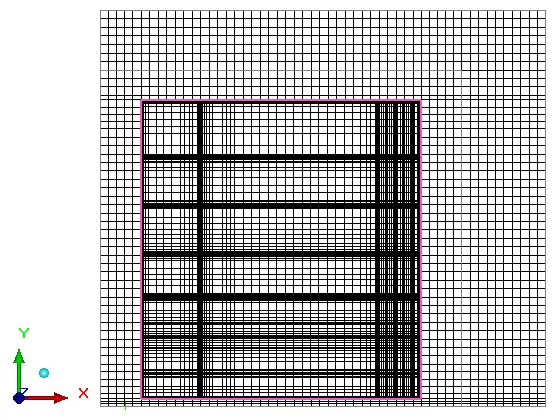 Fig. 6a.
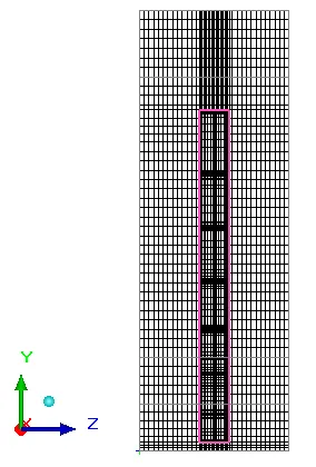
Fig. 6b
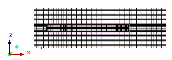 Fig. 6c
The mesh quality was found to be very good.
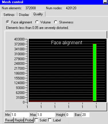 Fig. Face Alignment
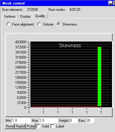 Fig. Skewness
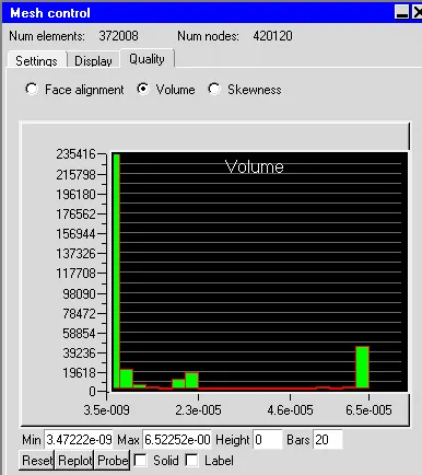 Fig. Volume
Step 4
Boundary conditions:
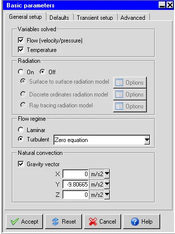
The given problem is solved for velocity and temperature variables under steady state condition considering zero equation turbulence model. The gravity vector is turned on for natural convection. The ambient temperture is considered to be 25oC.
Step 5:
Results
Temperature contour
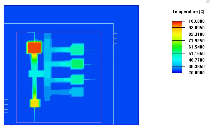 Fig. 7 Temperature contour inside the cabinet
Fig. 8 shows the velocity vectors
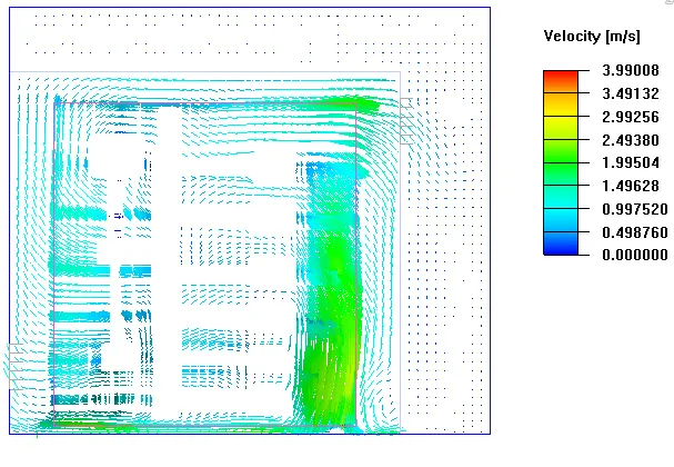 Fig.8
Fig.8
Fig. 9 shows the temperature of the circuit breakers and bus bars. The maximum temperature is found to be 103oC in the IG circuit breaker since maximum heat loss is there in the CB.
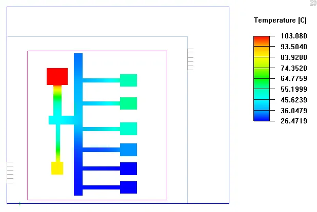
Fig. 9 Temperature contours of CBs and BBs.
Fig. 10 shows the Particle traces
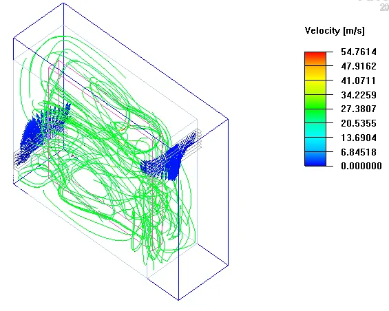
Fig. 10 Particle traces
Fig 11 shows Velocity contour in the cabinet. The maximum velocity inside the cabinet is found to be 4 m/s approx.
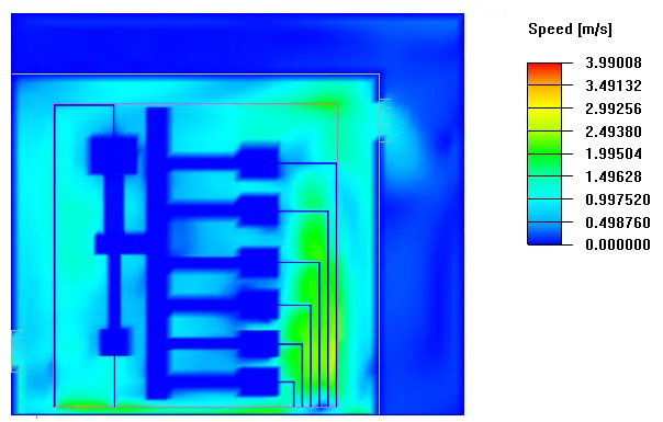
Fig. 11 Velocity contour
Conclusion:
It is seen from the contours of temperature, that the maximum temperature of the circuit breaker is bit high but but not exceeding the melting point of copper. Proper enclosure is to be designed for the movement of air around the circuit breaker in order to reduce the temperature.