Week 5.3 - Forced convection Analysis
Aim: To simplify the given CAD object and study the simplified object for forced convection
Introduction:
The given electronic assembly consists of a front panel,fan, rear panel with openings, housing. Inside the housing, the assembly consists of PWB (Printed wiring board), coils, BGA package and heat sink, 3 capacitors, 4 components, HS AF0, 6 numbers of TO-220 electronic package, 18 lead AF0, 6 semi conducting electronic dies. It is required to analyze for forced convection condition.
Assuming the components like BGA, Coils are generating a heat of 10 W and, Dies are generating a heat of 3 W.
Procedure:
Step 1: The initial setup for the problem is set up in the Ansys workbench as shown in Fig. 1
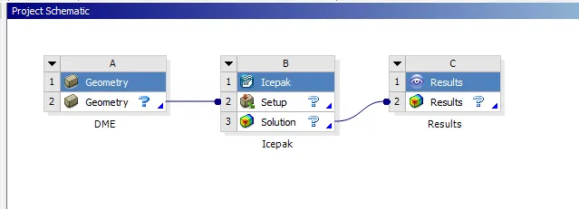 Fig. 1 Setting up of the problem
Step 2: The CAD objects are converted to icepak objects in Spaceclaim
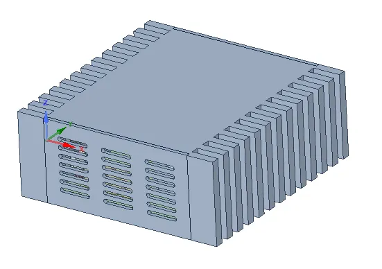
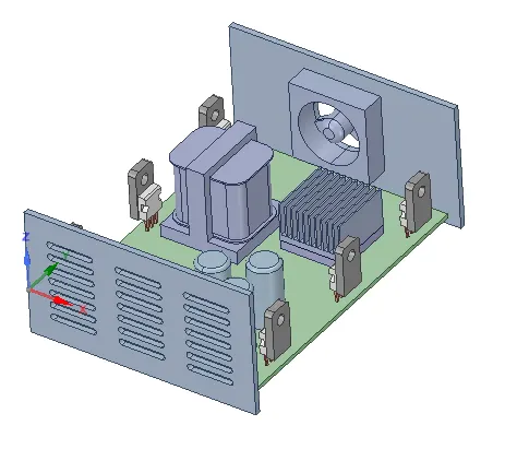
Fig. 2 CAD objects
Step 3: In the workbench menu, using icepak simplify, the CAD objects are converted to icepak objects with level 3 simplification type as shown in fig. 3.
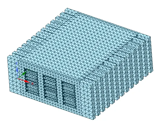
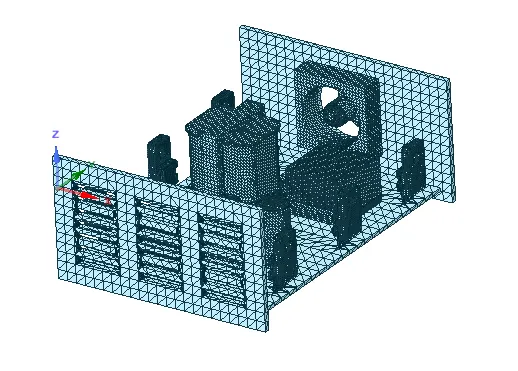
Fig. 3. Icepak objects
Step 4: The icepak objects is transfered and analysed in Ansys icepak
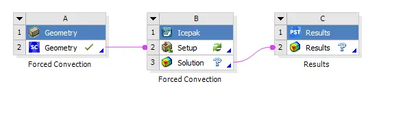
Fig. 4. Icepak setup in workbench
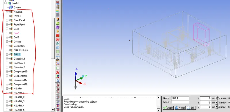
Fig. 5 Renaming of the components
Step 5: Giving the input condition for electronic Die, coil and BGA as shown in the figures 6, 7 and 8 respectively.
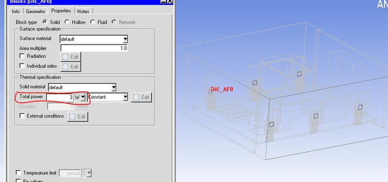
Fig. 6 Total power input for electronic Die component
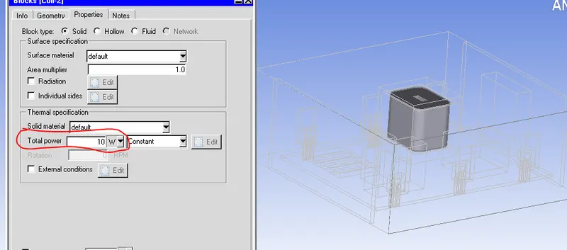
Fig. 7 Total power input for coil
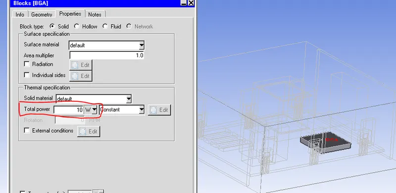
Fig. 8 Total power input for BGA
Step 6: Cabinet specifications
The Min X and Max X were given wall boundary conditions and the heat transfer coefficient of 5 W/m2k is specified for both conditions. Also, the Min Y and Max Y were given opening and the temperature is at ambient conditions as shown in Fig 9a and 9b respectively.
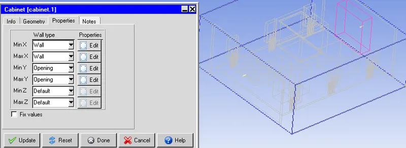
Fig. 9a Cabinet specifications
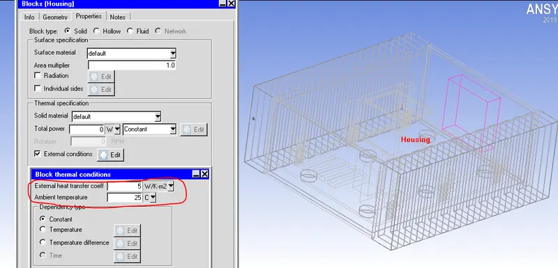
Fig. 9b Heat transfer coefficient specified for MinX and Max X
Also, the fan velocity was given a velocity of -2 m/s (Assuming flow in Positive direction)
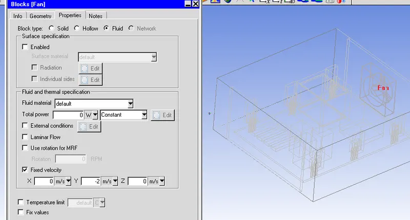
Fig. 10 Fan boundary conditions
Step 7: Meshing
For the first step, the coarse mesh is generated and the number of elements is found to be 0.6 million as shown in fig 11.
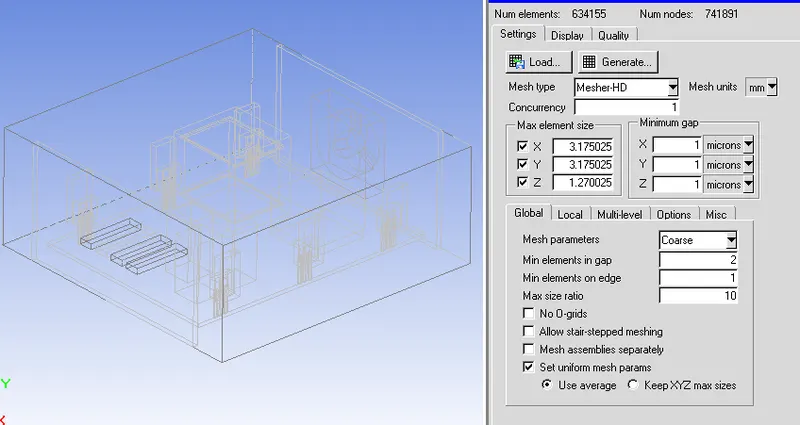
Fig 11: coarse mesh
The coarse mesh in x, y and z directions is shown in Fig. 11 a, b and C respectively
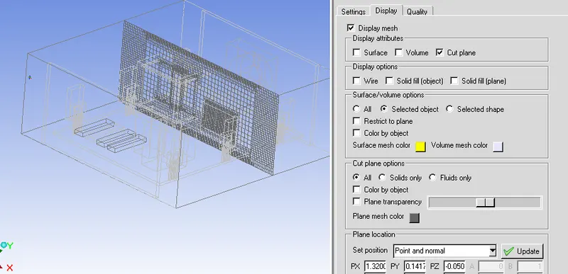
Fig. 11a Cut plane mesh in X direction
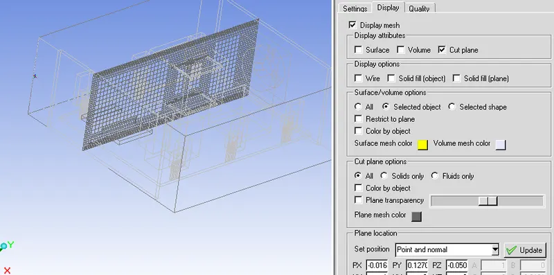
Fig. 11b Cut plane mesh in y direction
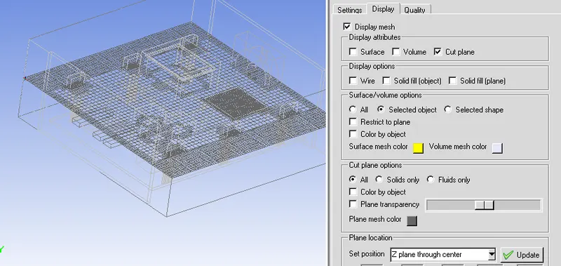
Fig. 11a Cut plane mesh in z direction
Now, the volume mesh of for heat sink is shown in Fig. 12. Initially the CAD object is not properly meshed. later with multilevel meshing of 2 for heat sink, a good mesh is generated.
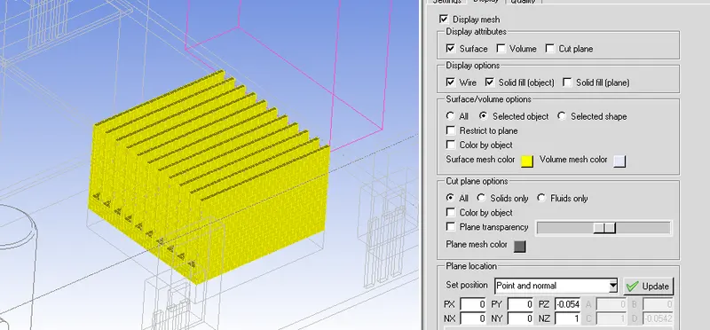
Fig. 12. Heat sink mesh
Step 8: Problem setup
A steady state forced convection heat transfer problem is created for turbulent flow condition. the k-epsilon turbulence model is used for the present problem.
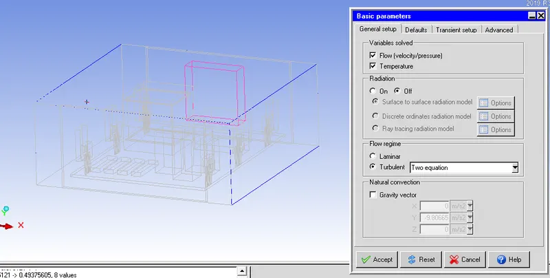
Fig. 13. Problem setup for forced convection
The problem is setup with basic settings, and in advanced conditions, with double precision, the second order discretization scheme is used for all the equations.
Step 8: Solution
After achieveing the convergence, the following results were obtained. Fig 14, 15 and 16 show the velocity plot, temperature plot and particle traces.
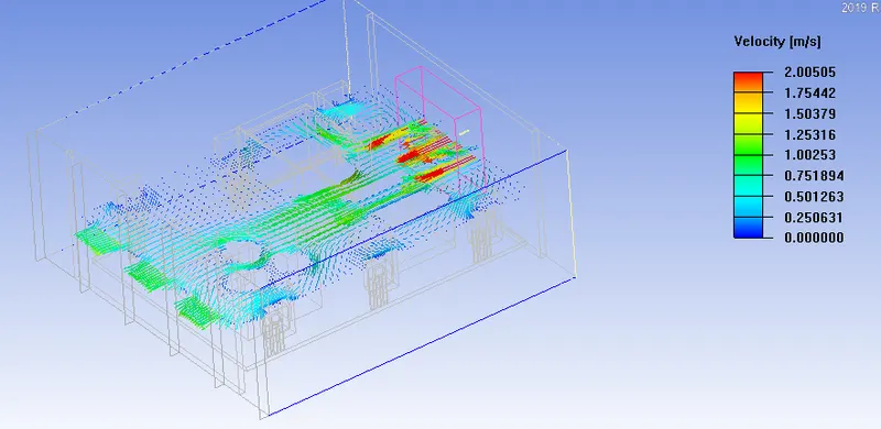
Fig 14. velocity plot
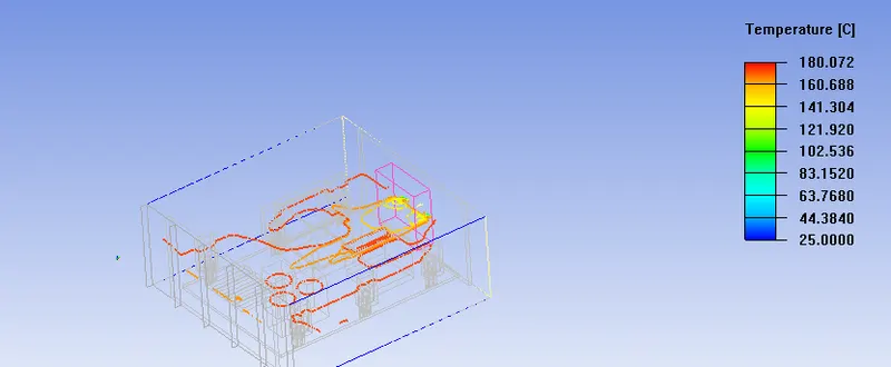
Fig. 15 Temperature plot
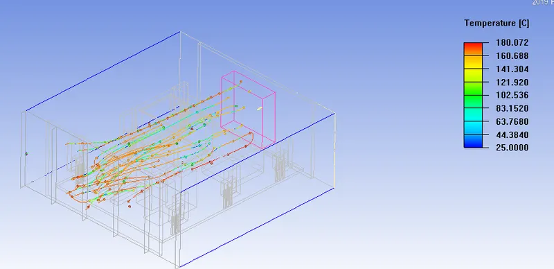
Fig. 16 Particle trace
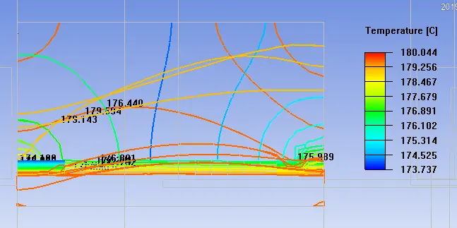
The object face for heat sink
Mesh independence study:
The CAD object is again meshed and the number of elements if found to be 1.3 million.
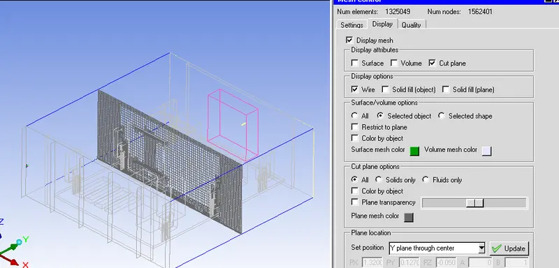
Fig. 17 the Y plane mesh.
2nd mesh:
For the same boundary conditions mentioned above, the simulation is performed and the results are shown below.
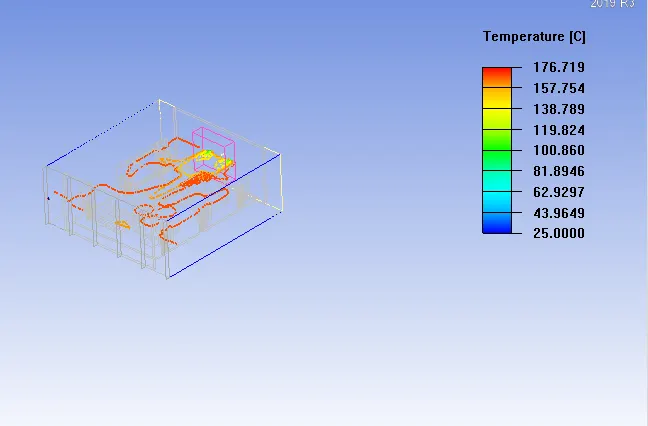
Fig. 18 Temperature plot
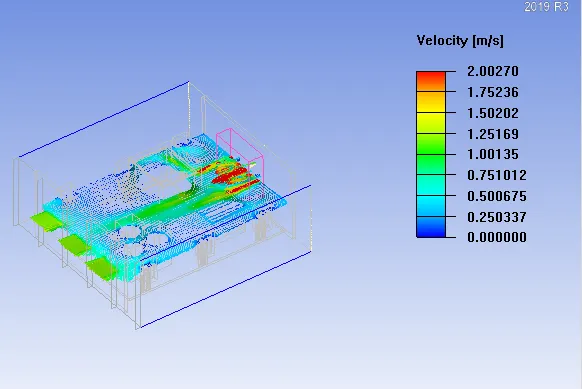
Fig 18 Velocity plot
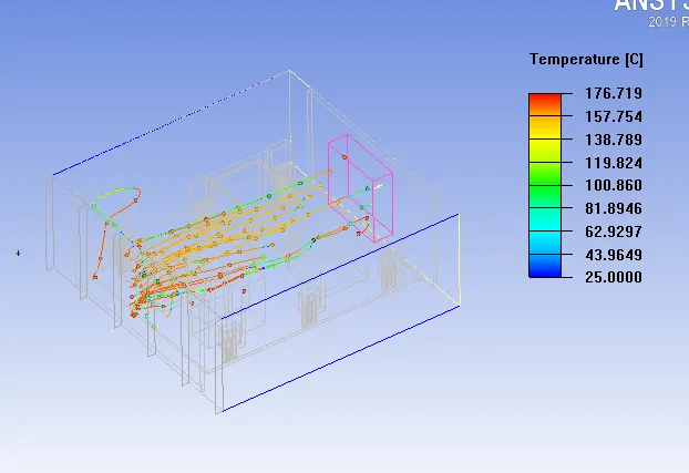
Fig 19 Particle trace
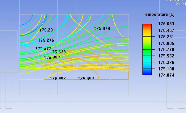
Object face for heat sink:
Result:
The given CAD object was solved for the forced convection problem assuming an heat input of 10 W from the coils and 3 W from Dies. The problem was solved for a turbulent flow condition and k-epsilon turbulence model is chosen for modeling the turbulence. The approximate Reynolds number was found to be 65000 for the present condition. The inlet velocity was considered to be -2 m/s in y-direction.
After solving the problem for forced condition, the temperature and velocity plots are plotted and the particle traces are indicated. The surface temperature in the heat sink was found to be 176 degree C for the given heat input.