Week 5.1 - Non-Conformal Meshing and Solving a Cold plate model
Aim: To Analyse the heat transfer characteristics in the given cold-plated assembly.
Introduction:
The model includes two heated plates, cooled by water circulating inside the cold-plate cavity, as well as by air driven by natural convection externally. Separately meshed assemblies will be employed to reduce the overall mesh count in the domain.
Procedure:
Step 1: Generate the model
1. The cabinet is resized as per the given dimension and is shown in figure 1.
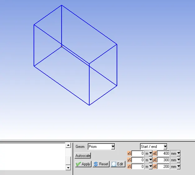
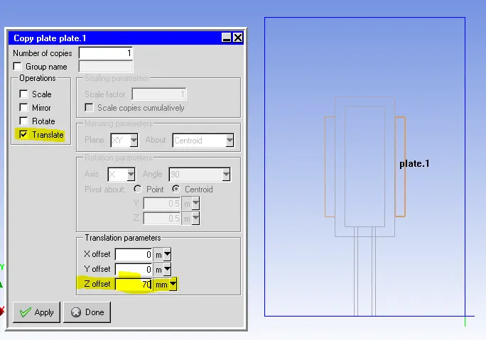
Figure 1: Cabinet
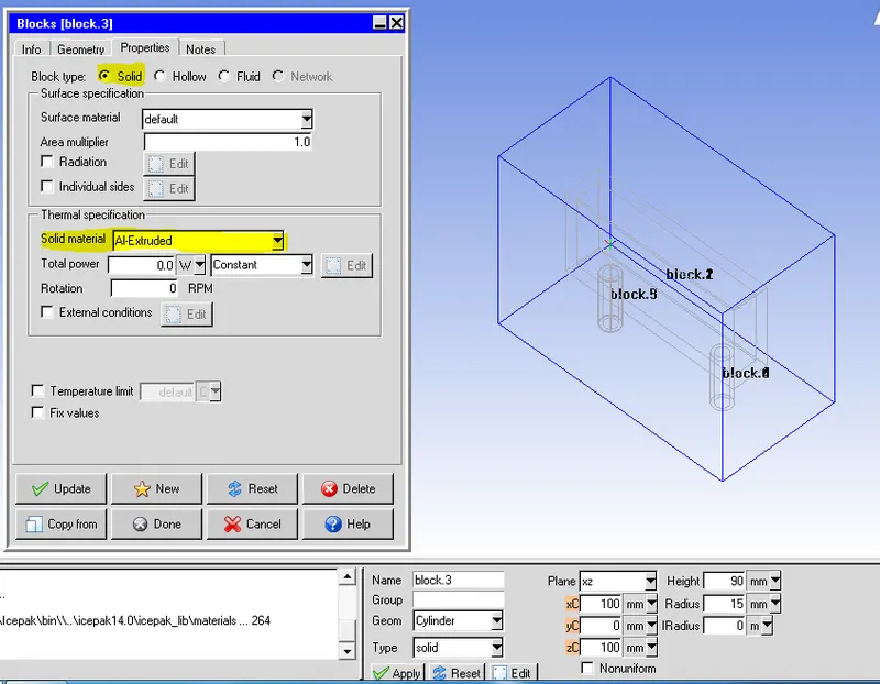
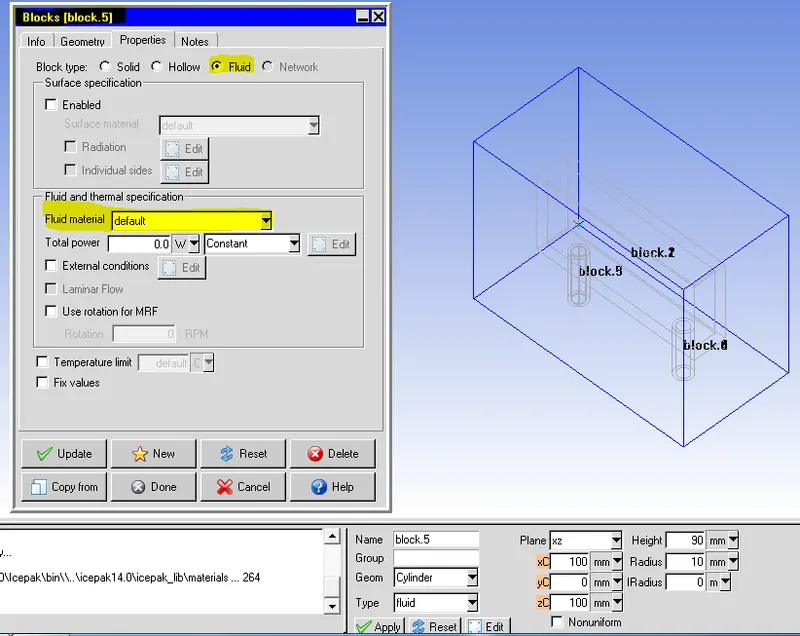
2. Create the solid and fluid block:
For solid block, 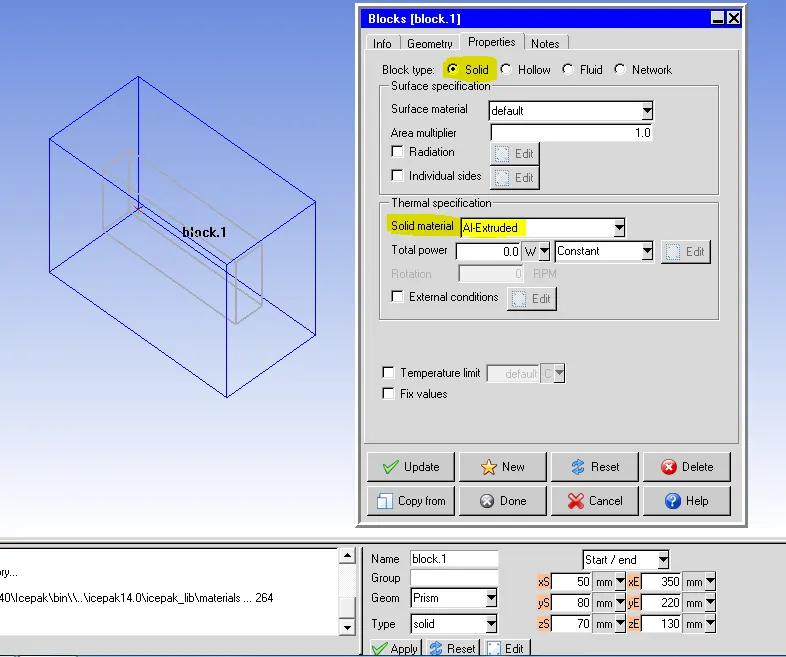
For fluid block:
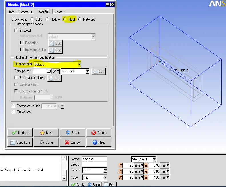
3. Solid block 2
and fluid block 2
4. Create plate 1
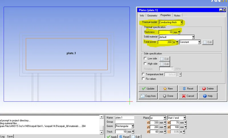
Create: Plate 2
Copy the plate1 and translate 70 mm in Z direction
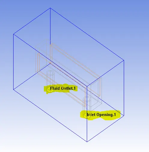
5. create a fluid opening for the inlet and outlet as per the dimensions given
6. create cabinet opening at Min X and Max X
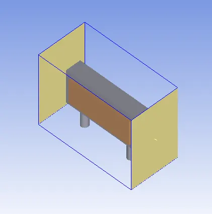
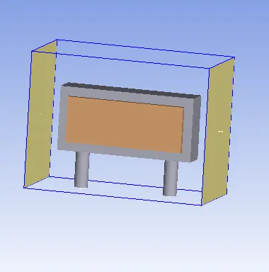
The final model is as shown below.
Step 2. Create assembly.
1. Select all the blocks, plates, and fluid inlet and outlet to create an assembly.
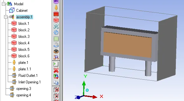
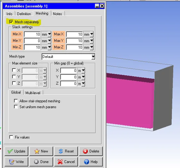
2. For the Assembly, check the Mesh separately option and enter the slack values as shown below.
Step 3: Generate Mesh
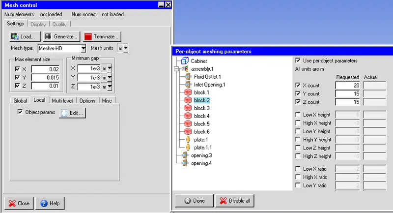
1. click on Generate Mesh and in the local option select object parameters and enter the per-object parameters as shown below.
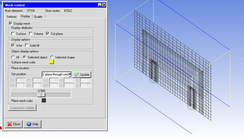
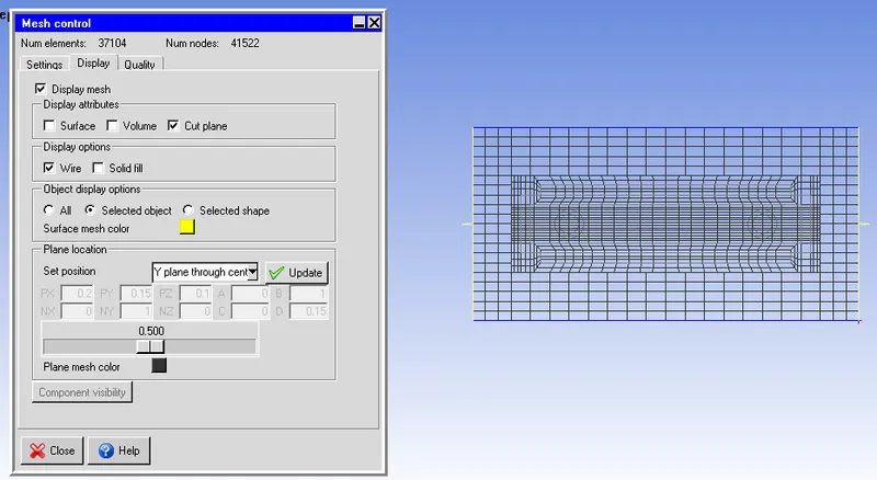
2. visualize the mesh in Z and Y plane as shown below
Step 4: Problem setup
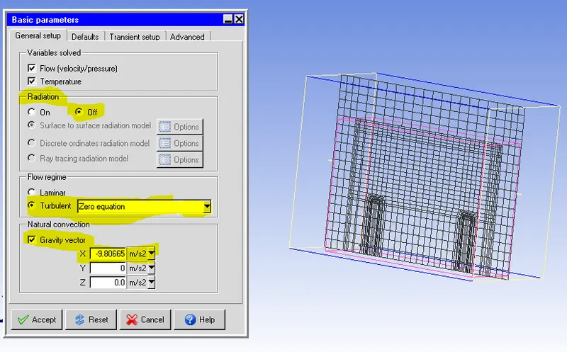
1. The problem is solved for velocity, pressure, and temperature for transient setup. Zero equation turbulence model is chosen for the problem. The gravity vector is set up in this problem. since Gravity acts in the negative x-direction, therefore the value of X is mentioned as -9.8 m/s2
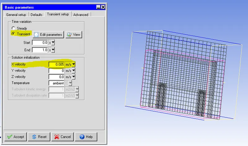
2. The approximate values of Ra and Pr is estimated and is shown below.

3. The iterations per time step is mentioned as 20.
4. The monitor points are set up for block 2, fluid inlet & outlet, and plate. (Right-click on the object to be monitored and select create option and select monitor)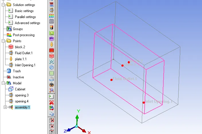
5. The solution is started by choosing the 'run solution' option.
6. The solution will be is seen which is solved for the continuity equation, x, y, and z momentum equations, and energy equation.
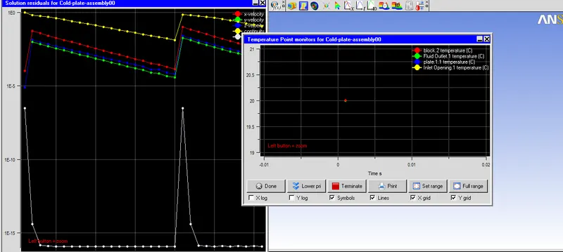
Step 5: Examining the results
1. Velocity (vector) plot through the inlet and outlet opening.
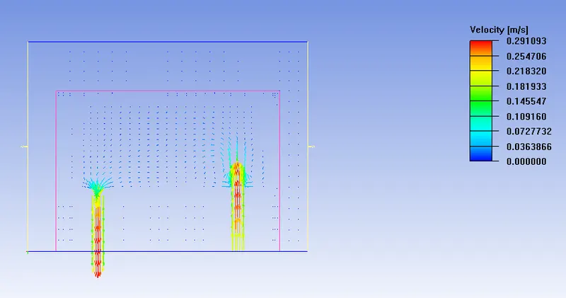
It is seen from the vector plot that the velocity is maximum in the center of the pipe.
The temperature of the objects
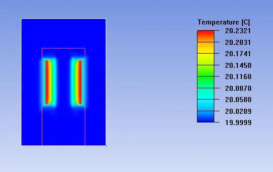
From the temperature plot, it is clear that, in the X-plane, the temperature distribution is symmetric about the Y-axis. The maximum temperature is found to be 20.23oC.
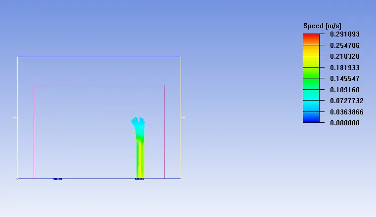
particle trace in the inlet and outlet opening
Animation: