Week - 4 - Crash Box Simulation
*Aim:-
-Simulate the crash box model using the LS-DYNA software & understand the concepts of how the conditions produce after the heating car to any particular steady object(Rigid wall)
Objective:-
-In this simulation, we request for the given delivers & compare the results for a 1.2 mm thick & 1.5 mm thick crash box
*Deliverables:-
- Input .k file and output files (d3plot, glstat, sleout, rcforc)
- Animation of the final simulation
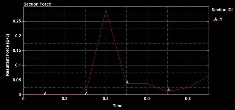
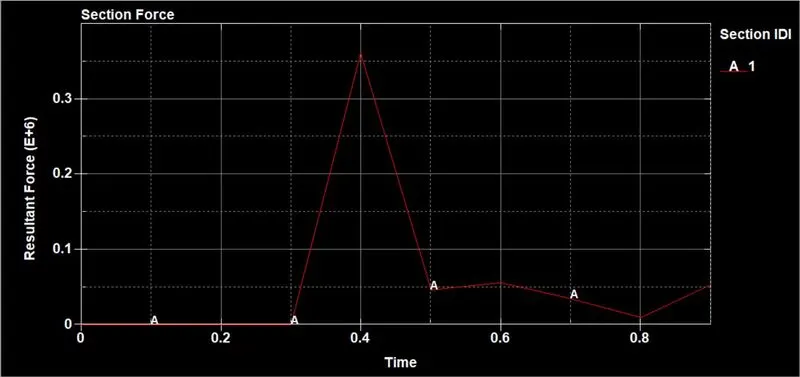
- Cross-sectional force generated in the middle of the crash box (along its length)
- Acceleration plot of a node in the middle of the crash box (along its length)
- Maximum directional stress and strain along the length of the crash box (X strain, Y strain etc)
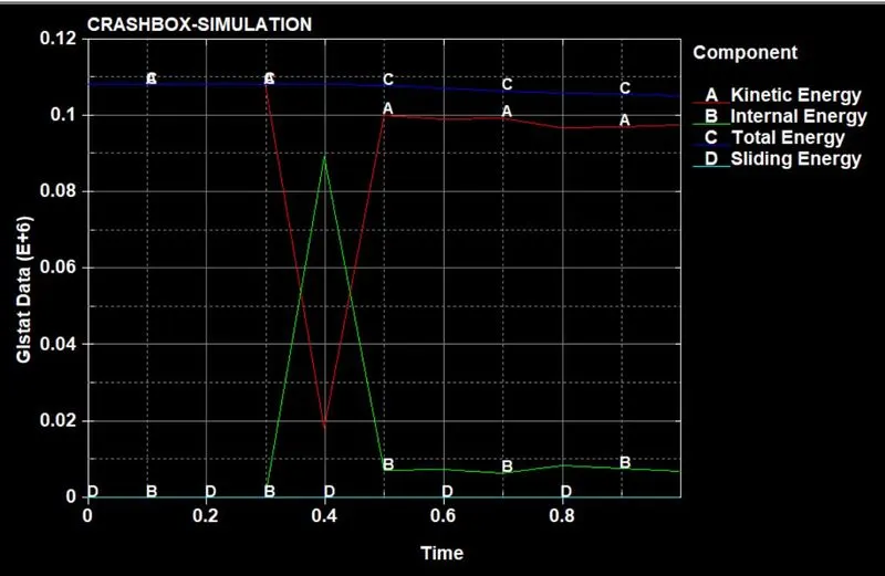
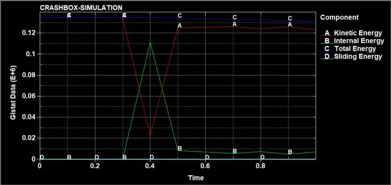
- Plot of all energies (total, internal, kinetic, hourglass, sliding)
- Compare the accelerations and stress/strain plots of 1.2/1.5mm crash boxes
Crash box test is to be conducted by creating all the necessary input keywords:-
- Material creation
- Section creation
- Assigning material & section to their respective parts
- Rigid wall creation
- Defining boundary conditions & specifying initial velocity to the box.
- Creating the contact definition.
- Model termination to be assigned
- Binary_D3plot & ASCII_opction define
- Plotting the result
*Unit system:-
-in the question given, the unit system is:- gm, mm, ms
*Procedure:-
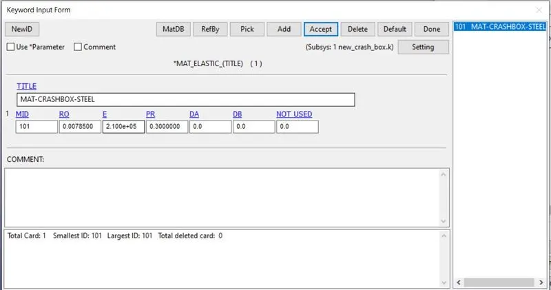
1) Material:-
We create a material card for the shell
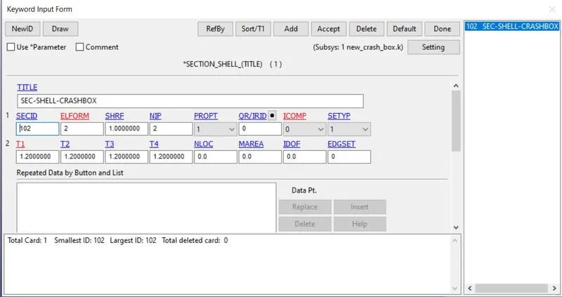
2) Section creation:-
-Session shell is taken for the crash box.
-For that we go to Model & part>keyword manager>all>section
-Here provide the element formulation is 2 & thickness is 1.2 mm/1.5 mm
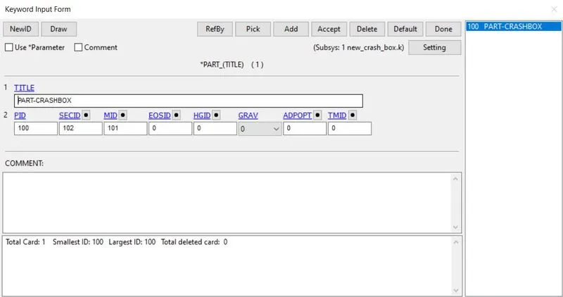
3) Assigning material & section to their respective parts:-
-After the creation of the material & session, the next step is to create the part
-Here there is one part produce. provide the material id and section ID
4) Rigid wall:-
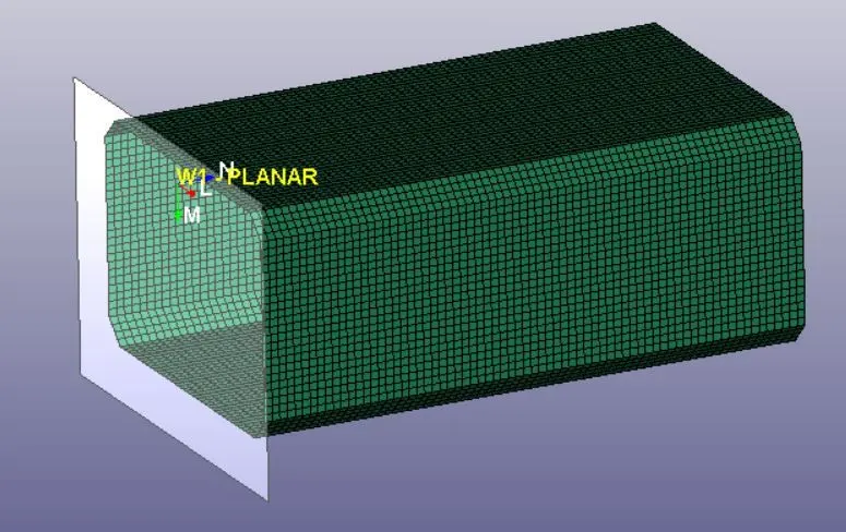
-Now we create the rigid wall
-For that first of all create a new node-set
-For that go to model & part>create> Set data> set node
-Here ew select all nodes of the crash box
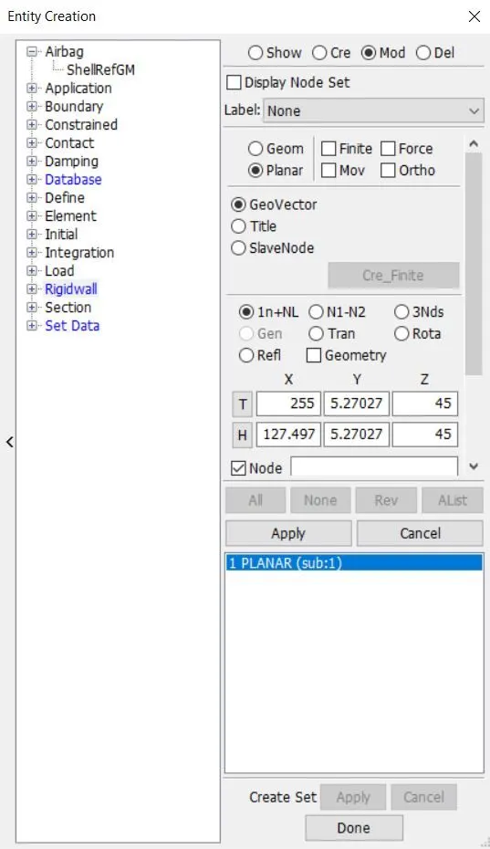
-Now we create the rigid wall
-For that go to model & part>create> Rigid wall> rigid wall
-Choose create button and go with planer type
-After that create a wall, and set using just like transalate and rotate opction
-Provide the distance between end of the crash box & rigid wall is 10 mm
5) Definding boundary conditions & specifying initial velocity to the box:-
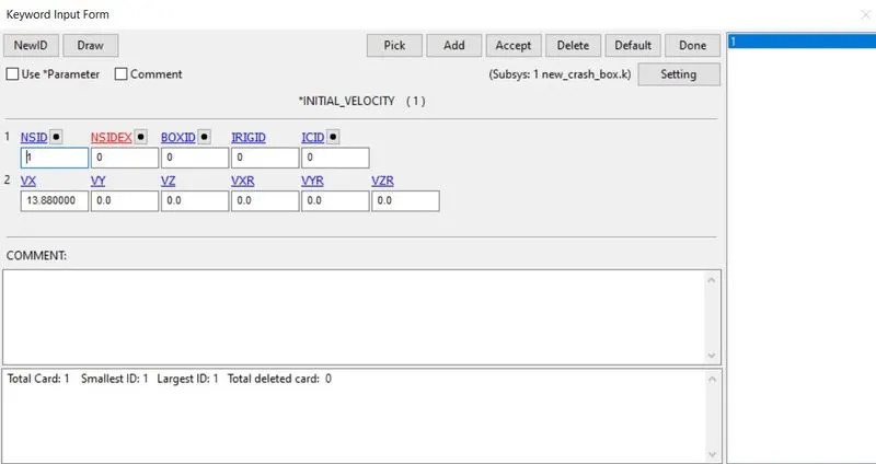
-Now we provide the velocity to the box
-In the question velocity given is 50 kmph (13.88 mm/ms^2)
6) Creating the contact definition:-
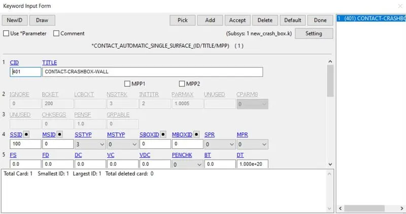
-We create the self contact for a crash box
-For that go to the Model & part>keyword manager>all>contact
-Choose Automatic_single_surface type
-Here we select the slave type is 3(by part) & only select the slave id, don't select the master ID
7) Model termination to be assigned:-
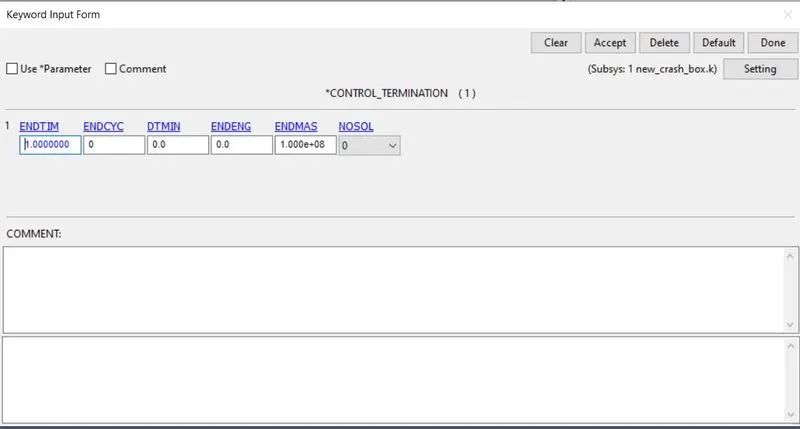
-Now we create control termination card
-Control_termination keyword is crated for the end time provide. we provide end time is 1 ms
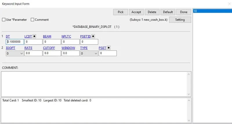
8) Binary_D3plot & ASCII_opction define:-
*BINARY_D3PLOT:-
In this keyword the frequency with which the animation is to be crated will be given and is set to 0.01 ms
9) ASCII_OPCTION KEYWORD:-
-in this keyword
- GLSTAT-Global data
- MATSUM-Material energies
- NODOUT
- RCFORC
- RWFORC
- SLEOUT
- SECFORC
- NODEOUT
Plotting the result:-
Thickness 1.2:-
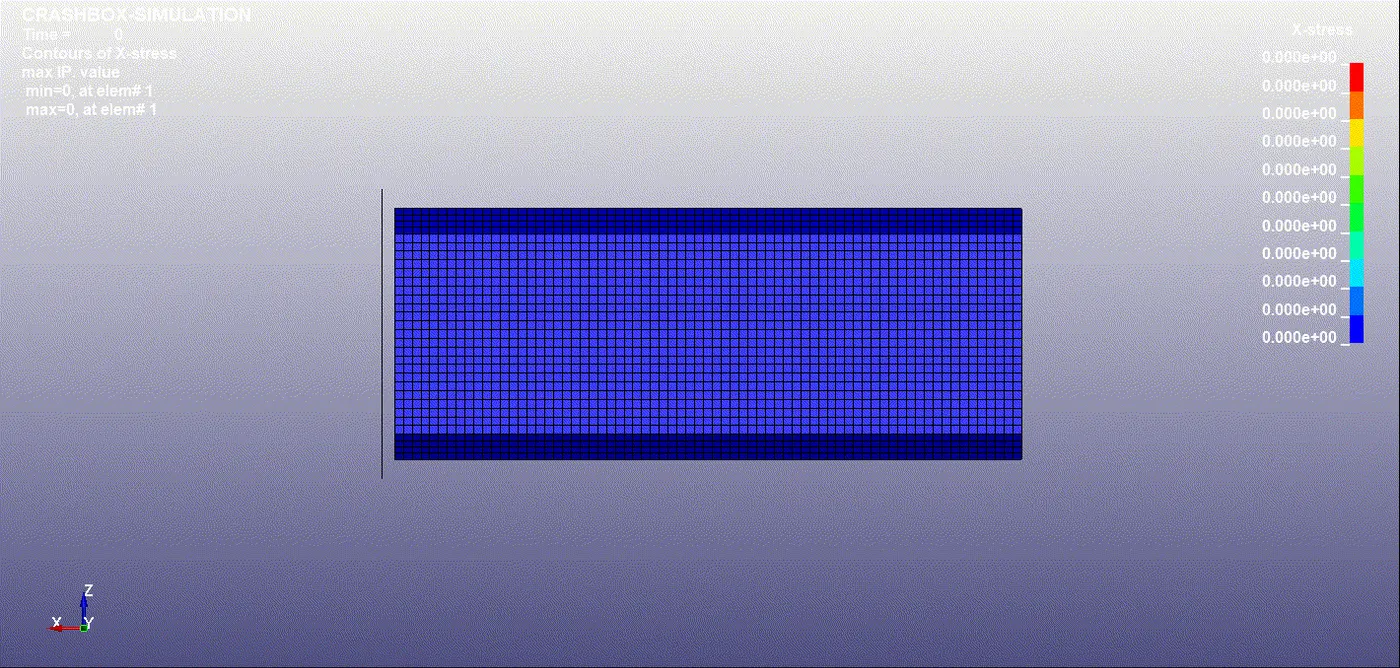
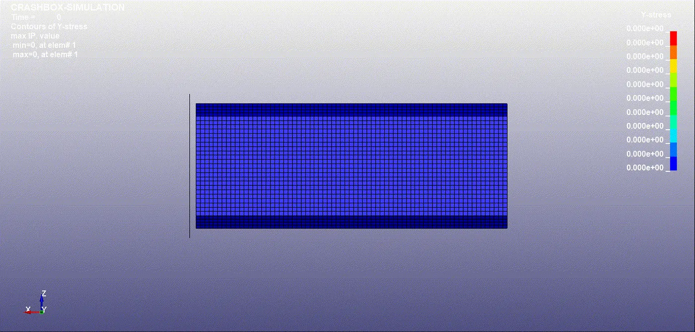
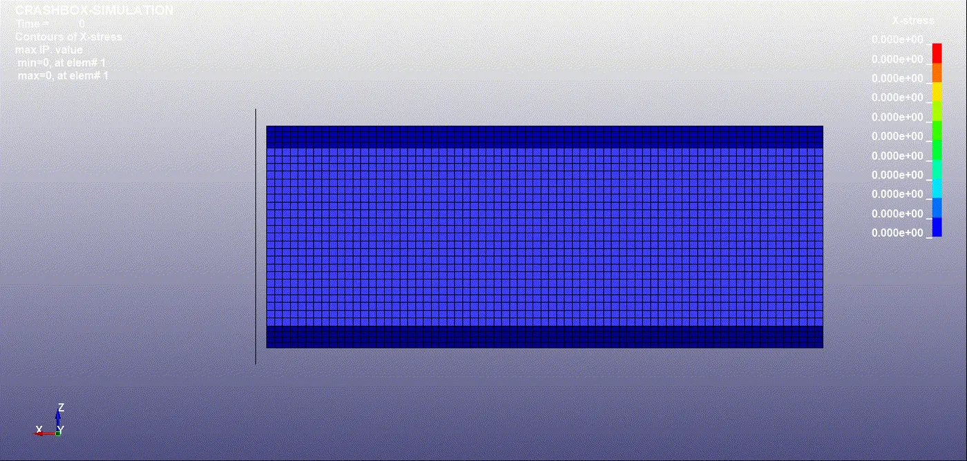
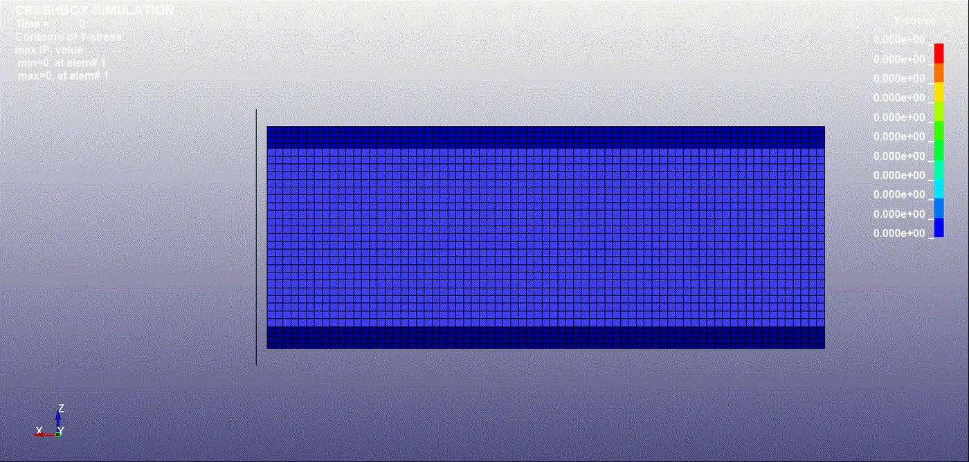
1) X and Y Stresses:
t = 1.2 mm
t = 1.5 mm
2) X and Y Strain:
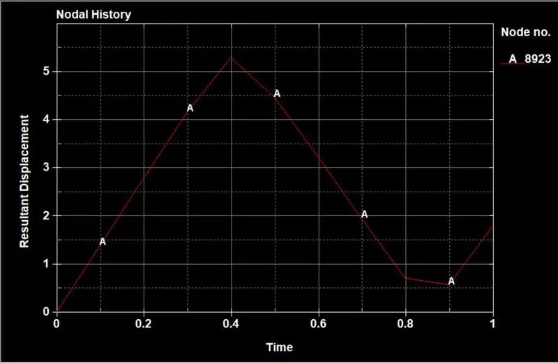
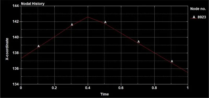
3) Nodal-Acceleration:
t = 1.2 mm t = 1.5 mm
4) Cross-Section Forces:
t = 1.2 mm t = 1.5 mm
5) Kinetic. Internal, Total and Sliding Energies:
t = 1.2 mm t = 1.5 mm
Conclusion:
- The solver deck is set up for the crash simulation & required results were requested using the appropriate *database keyword card
- The analysis ran successfully & post-processing results were done