Week - 4 - Crash Box Simulation
Aim:
The objective of this experiment is to simulate the crash test of a crash box and record the stress, strain and all the energies
Explanation:
Case setup/ Deck Setup (Keywords): gm,ms,mm Unit system
The keywords created are mentioned below.
- Section- SECTION_SHELL
Shell section is created using the above-mentioned key words and selectively reduced shell elements are used as they are economical from a computation perspective.
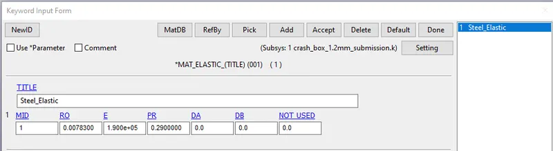
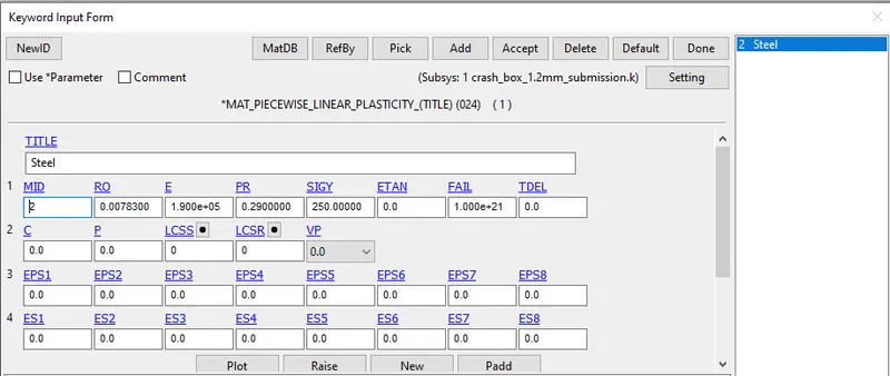
- Material- MAT_PIECEWISE_LINEAR_PLASTICITY
Two materials are used here.
One is for steel (Elastic MAT01) and other is for steel (Piecewise Non Linear MAT24) assigned to the crash tube
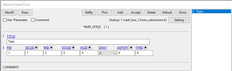
- Part definition - PART_PART
The created section ID and Material ID are then entered in PART card.
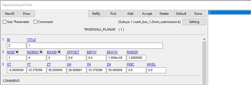
4. Rigid wall- RIGIDWALL_PLANAR

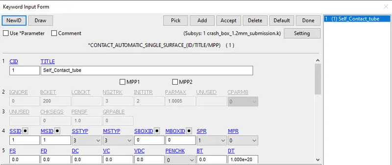
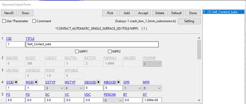
5. Contact - CONTACT_AUTOMATIC_SINGLE_SURFACE, CONTACT_FORCE_TRANSDUCER_PENALTY
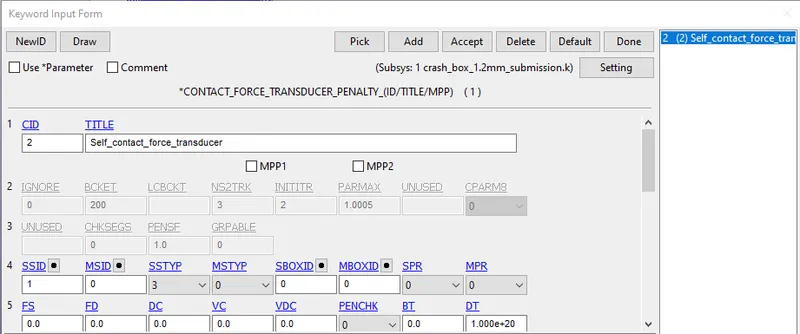
Force transducer penalty card is used because in case of single surface contacts, net contact force is zero and hence LS-Dyna doesn't write any data in the rcforc output file. Hence for single surface contacts, an additional force transducer penalty card is used to record data.
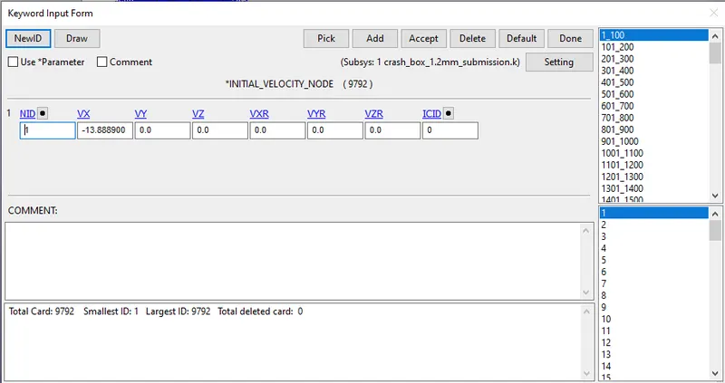
6. Load- INITIAL_VELOCITY_NODE
- Control- CONTROL_TERMINATION and CONTROL_HOURGLASS
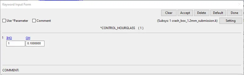
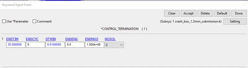
8. Database- DATABASE_ASCII and DATABASE_BINARY_D3PLOT
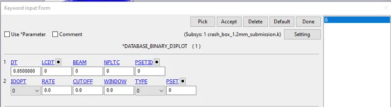
Animation:
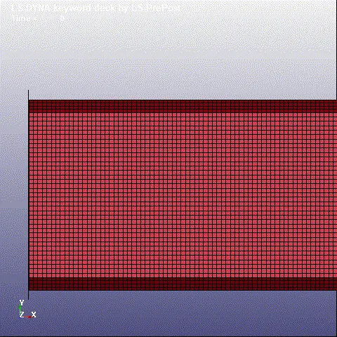
Since initial velocity is used for a part of considerable less mass with low velocity instead of prescribed motion, the tube crashes on the rigid wall and bounces off instead of crumbling and coming into self contact.
Plots & Contours:
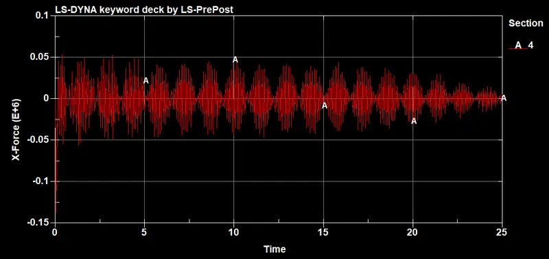
Cross-sectional force:
Since this is an impact simulation where a moving crash tube of less mass hits a rigid wall, the output will show fluctuating forces.
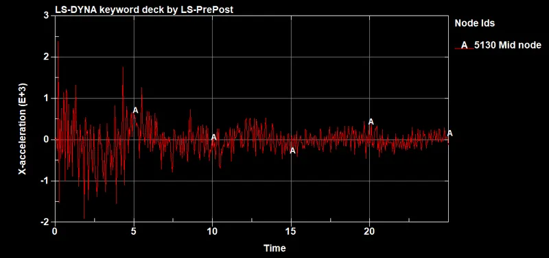
Acceleration plot of a node in the middle(Node ID 5130) of the crashbox:
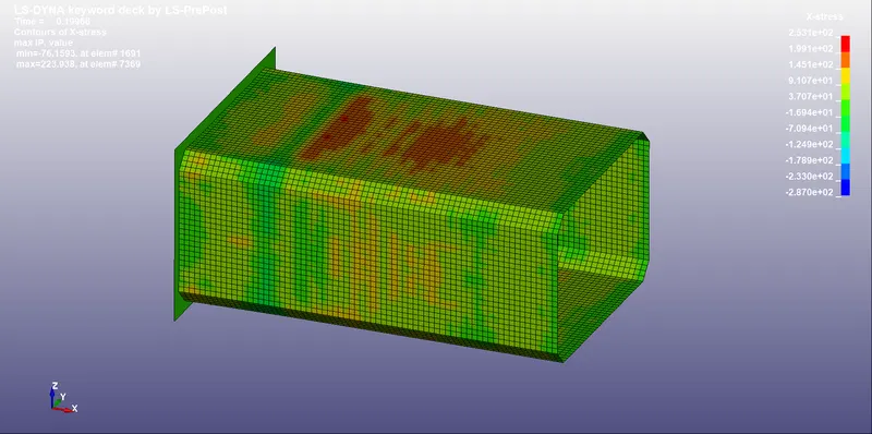
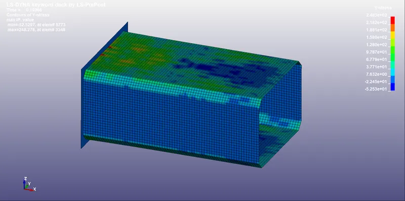
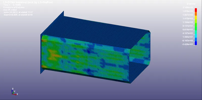
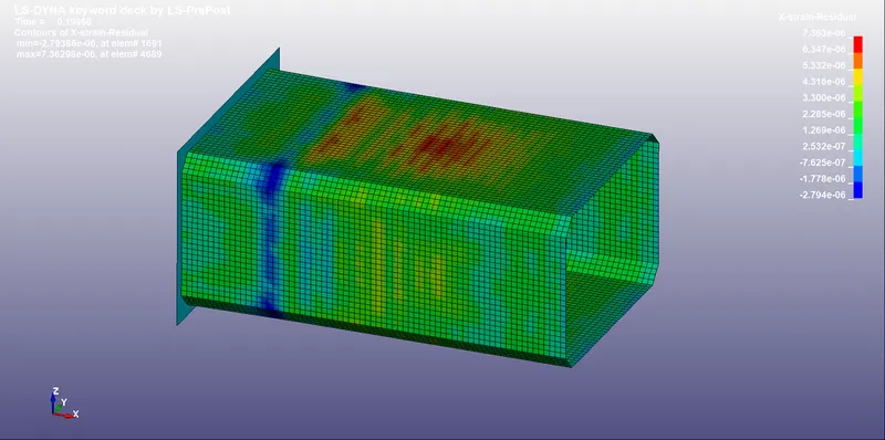
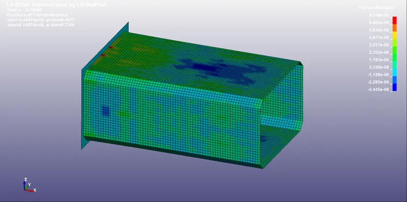
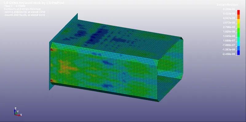
Maximum directional stress and strain along the length of the crashbox (X strain, Y strain, Z strain):
X Stress:
Y Stress:
Z Stress:
Directional elastic strain:
X Strain:
Y Strain:
Z Strain:
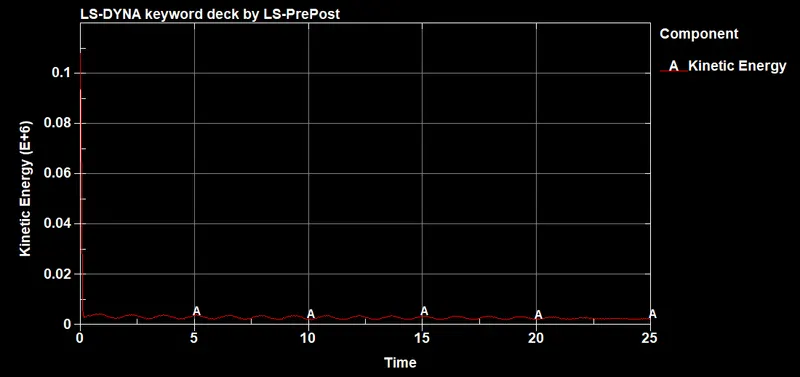
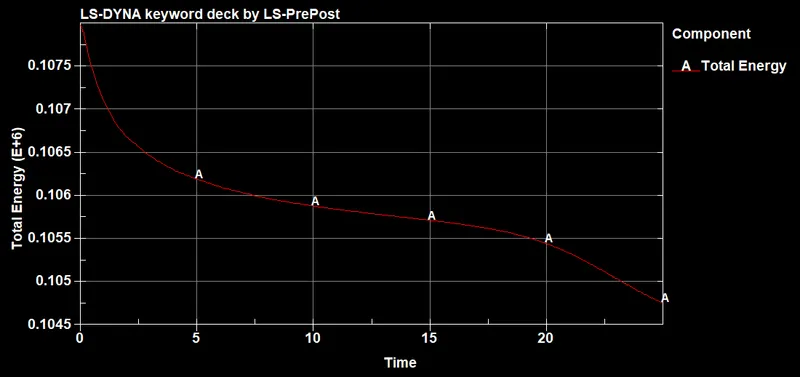
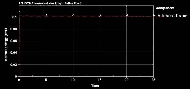
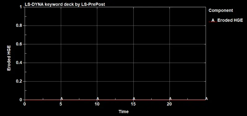
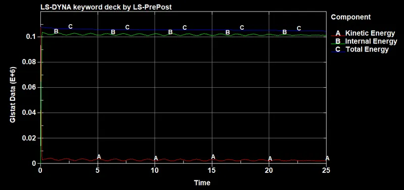
Energy Plots: Unit - N-mm
Comparison of acceleration and Stress/strain plots: Unit- Mpa
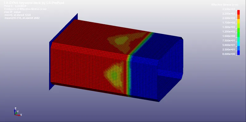
Von-mises Stress( 1.2 mm)
Von-mises Stress( 1.5 mm)
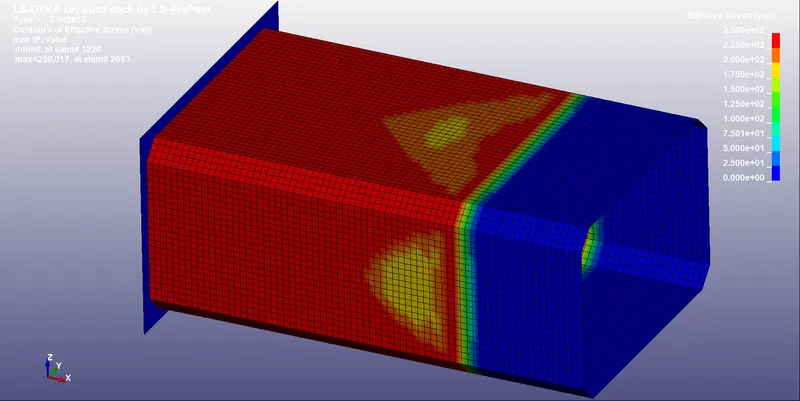
In both the cases, von mises stress is more or less the same except, in both the cases, different elements have the maximum stress.
Acceleration plot (1.2 mm):
Acceleration plot (1.5 mm):
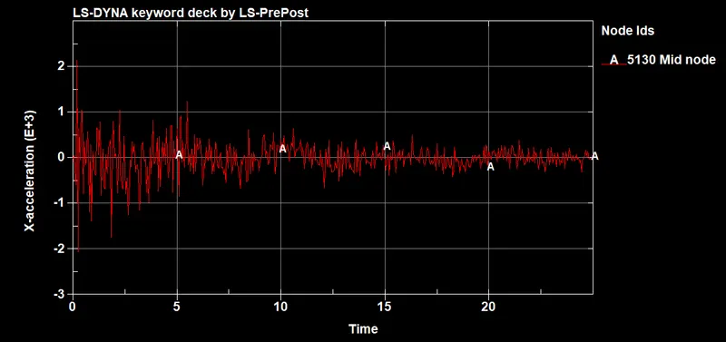
Comparison of acceleration plot:
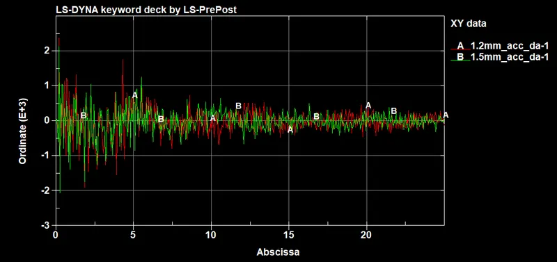
Due to the additional mass, the acceleretion has also changed a little.
Result:
Crash test of a crash box was successfully simulated and the contours and plots were presented
Conclusion:
The given meshed model was successfully used to build a LS-Dyna keyword deck and the Crash test of a crash box was successfully simulated with normal termination.