Week - 4 - Crash Box Simulation
AIM:-To perform the stimulation of the crash box by varying the thickness of 1.5mm and 1.2mm.
PROCEDURE:-
- Import the model into ls perpost.
- Apply the material property for the parts given.
- Apply the Section property to the parts in the model.
- Then after we need to give boundary conditions to the model.
- Then we need to give the runtime and time step to the model.
- We need to request the output results from the solver.
- Analyze the result from the solver.
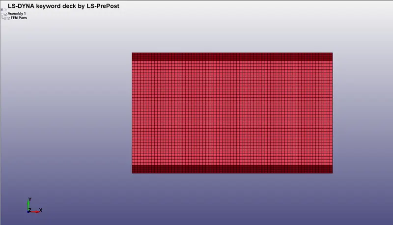
IMPORTING THE MODLE
- To import the model we need to open ls prepost and select file.
- Click on import select ls-Dyna binary polt and select the file location and press enter.
MATERIAL PROPERTY ASSIGNMENT
- For assigning the material property we need to go to keyword manager and select all.
- And then we need to go to MAT and select concerning material.
- Assigning the linear elastic material to the phone and rigid material to the ground
- And we are considering the material property of steel
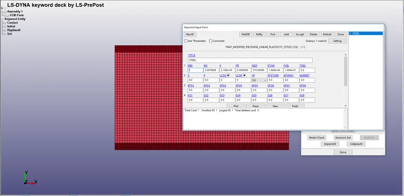
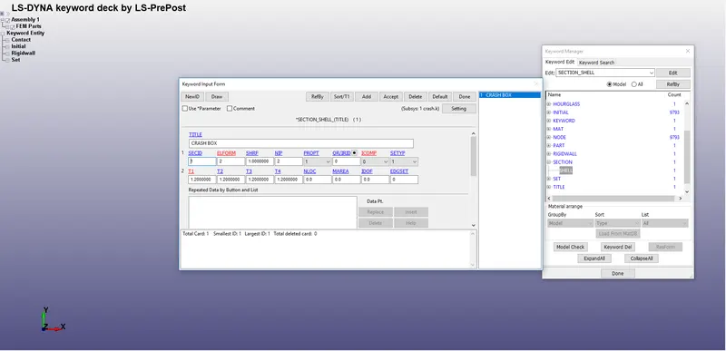
- As we are concentrate on the results of the crash box so no need to give an eq 2 and add an hourglass keyword to control the hourglass energy.
- But we must give a fully integrated formulation that decreases the hourglass and increases the accuracy of the solution or hourglass key can control.
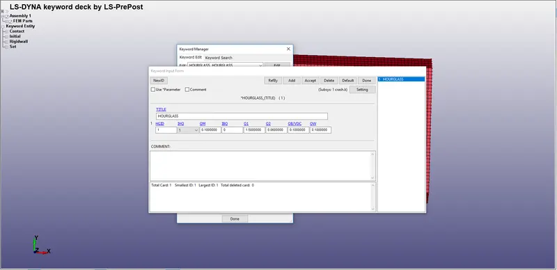
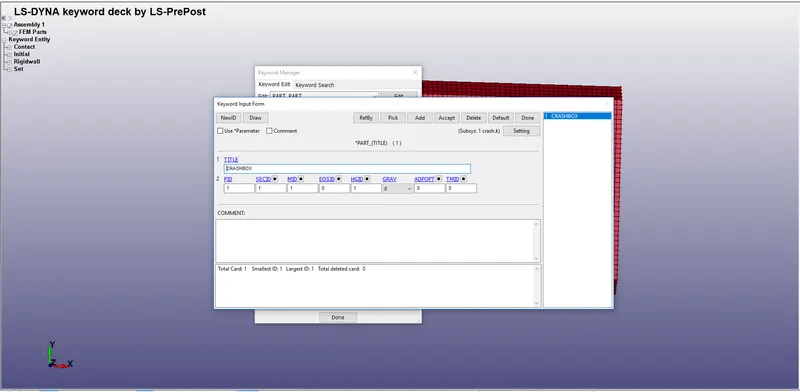
- we need to assign an hourglass to the part by giving HGID.
BOUNDARY CONDITIONS:-
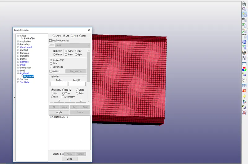
- First, we need to create a rigid wall.
- To create the rigid wall we need to go to entity creation and select rigid wall
- select planar and select on create then click on the node and by translate move the wall.
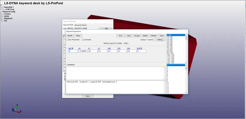
- After that, we need to give the velocity of 13.6 mm/ms
- To give velocity we need to select the initial and select velocity and select the nodes and apply.
- Before that, we need to go to constrained and select nodal rigid body and select the nodes.
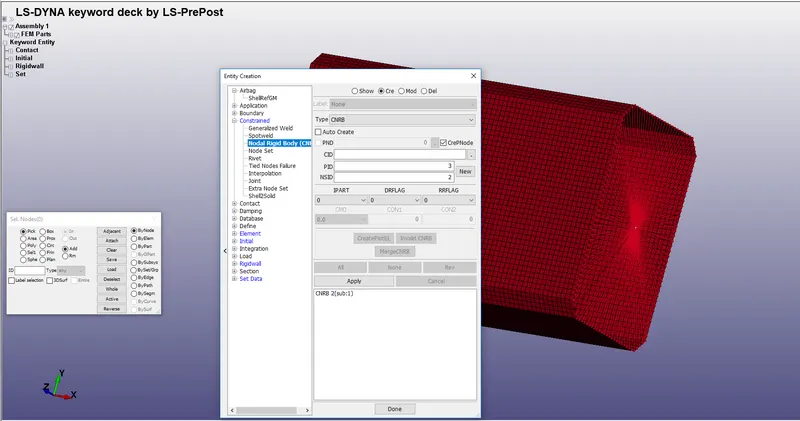
- Then after we need to mass to the CNRB to give mass we need to go to element and give the mass.
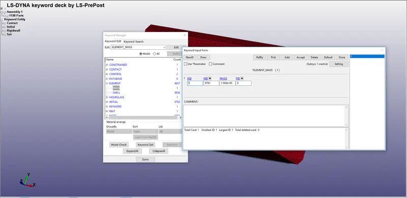
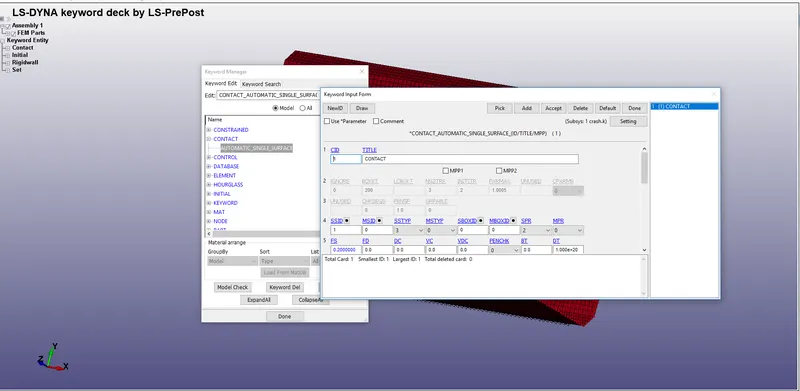
- After that, we need to give contact between them.
- In this, we can have automatic single surface contact in this we need to specify on the slave part crash box
- After that click on apply.
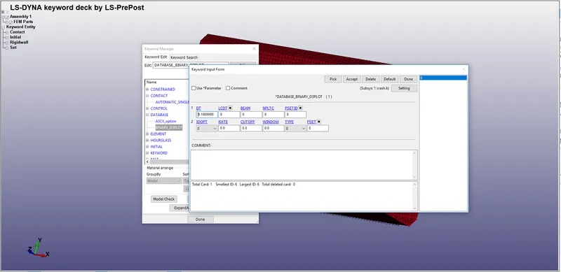
- After that, we need to request the output for the results.
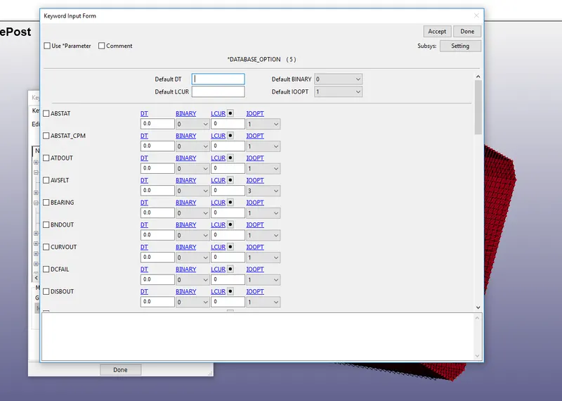
- To request the outputs we need to go to the database and select the ASCII option.
- And enable them to get the output results.
- DT is time to print the results out.
-
ELOUT:-database for element results for SSD (stress and strain
components).D3PLOT:-Database for the entire model.
GLSTAT:- file is the sum of internal energy of discrete elements.
MATSUM:- Energy values part by part.
SPCFRC:-Single point force constrained
- After that, we need to give the runtime.
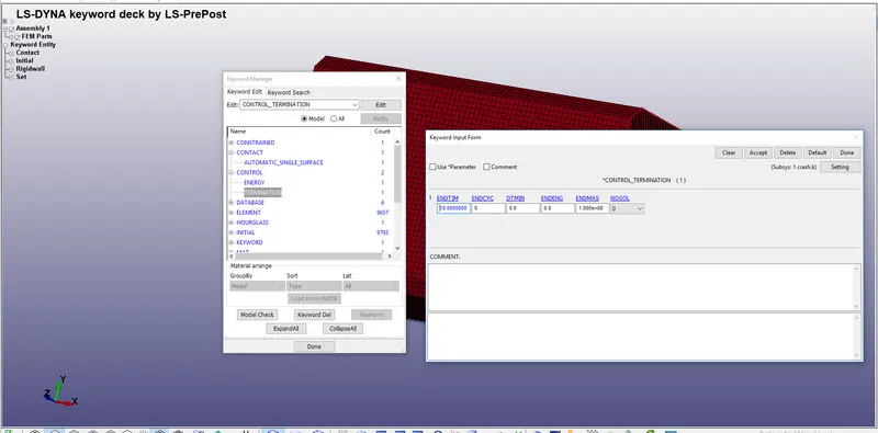
OUTPUT:-
CRASH BOX 1.2MM
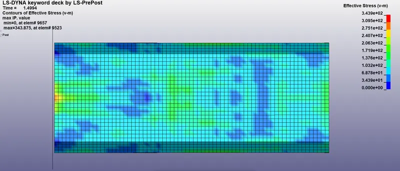
- The maximum von mises stress attained by the body is 343.9Mpa
- The yield strength of the material is 210MPa so that the component has undergone the plastic state.
- The material has undergone failure as per the theory of failure and we are observing the plastic behavior.
- So that the body will not come to its initial state.
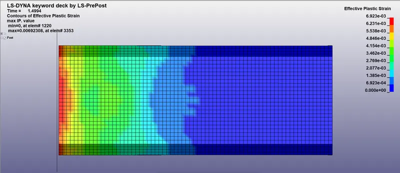
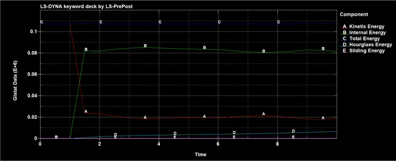
- As we can see that the component has contact with the rigid wall at 1.2 ms at that state the k.E decreasing and I.E is increasing
- The total Energy attained in this component is 107000 N-mm.
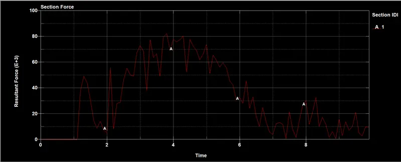
- From this graph, we can understand that the contact between the rigid wall and component happened at 1.2mm
- From that force is started increases it reached 82000N which is happened at 3.8mms at where the total force is been distributed
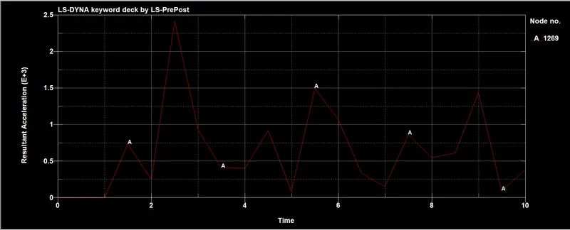
- If you see in the graph the after 1.2ms the highest acceleration is been is 2500 mm/ms^2 where it is been deceleration.
CRASH BOX WITH CRUSHING
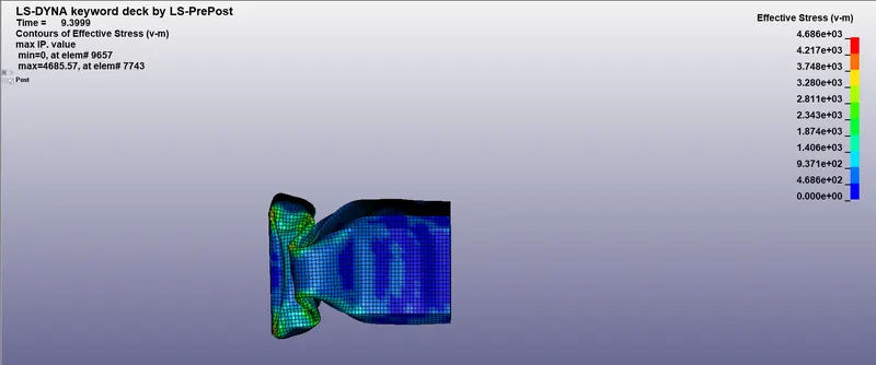
- The maximum von mises stress attained by the body is 468.6Mpa
- The yield strength of the material is 210MPa so that the component has undergone the plastic state.
- The material has undergone failure as per the theory of failure and we are observing the plastic behavior.
- So that the body will not come to its initial state.
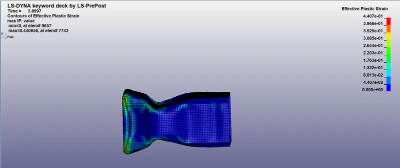
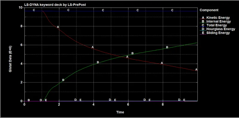
- As we can see that the component has contact with the rigid wall at 1.2 ms at that state the k.E decreasing and I.E is increasing
- The total Energy attained in this component is 9.63e+6 N-mm.
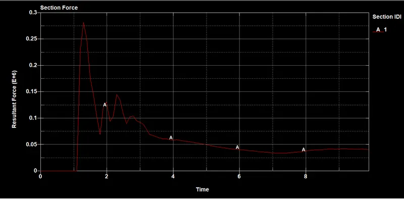
- From this graph, we can understand that the contact between the rigid wall and component happened at 1.2mm
- From that force is started increases it reached 28000N which is happened at 1.3mms at where the total force is been distributed
- As the mass is added to the component it will capable to resist the force up to a certain limit.
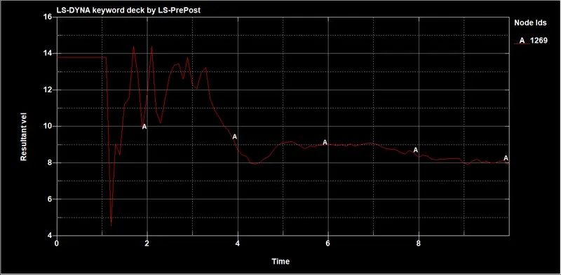
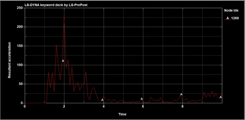
- If you see in the graph the after 2ms the highest acceleration is been is 225 mm/ms^2 where it is been deceleration.
CRASH BOX 1.5MM
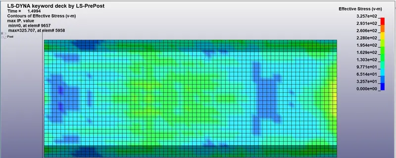
- The maximum von mises stress attained by the body is 325.7Mpa
- The yield strength of the material is 210MPa so that the component has undergone the plastic state.
- The material has undergone failure as per the theory of failure and we are observing the plastic behavior.
- So that the body will not come to its initial state.
- As the thickness of the component increases so that the stress developed is reduced it able to resist high forces.
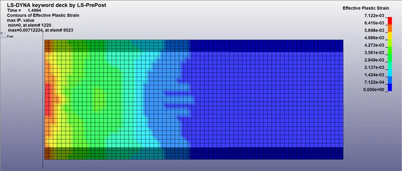
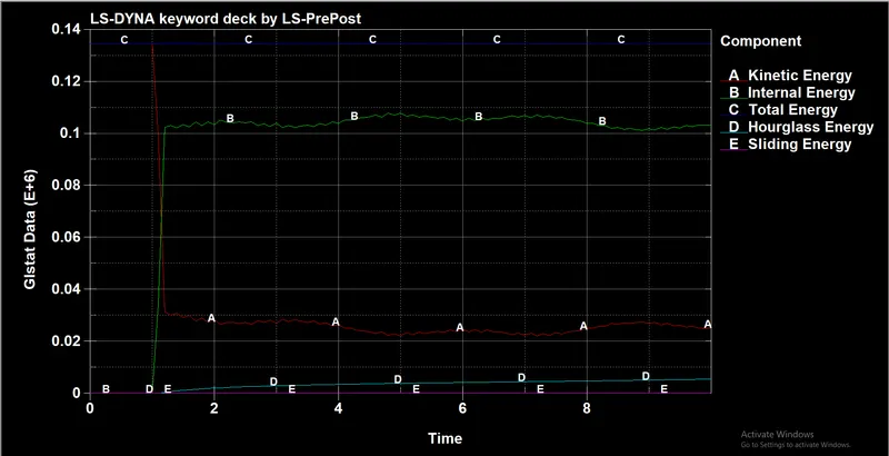
- As we can see that the component has contact with the rigid wall at 1.2 ms at that state the k.E decreasing and I.E is increasing
- The total Energy attained in this component is 1.35e+06 N-mm.
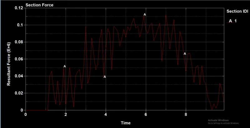
- From this graph, we can understand that the contact between the rigid wall and component happened at 1.2mm
- From that force is started increases it reached 0.11e+06 N which is happened at 6.7mms at where the total force is been distributed
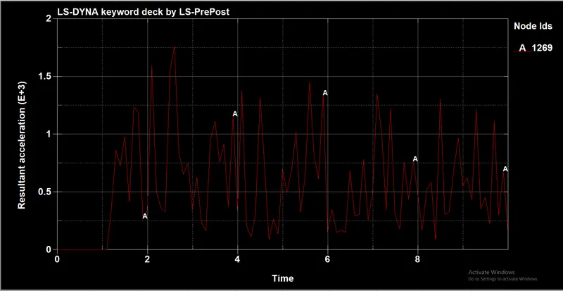
- As we can see that the acceleration is high at 2.3ms is 1.75E+3 mm/ms^2
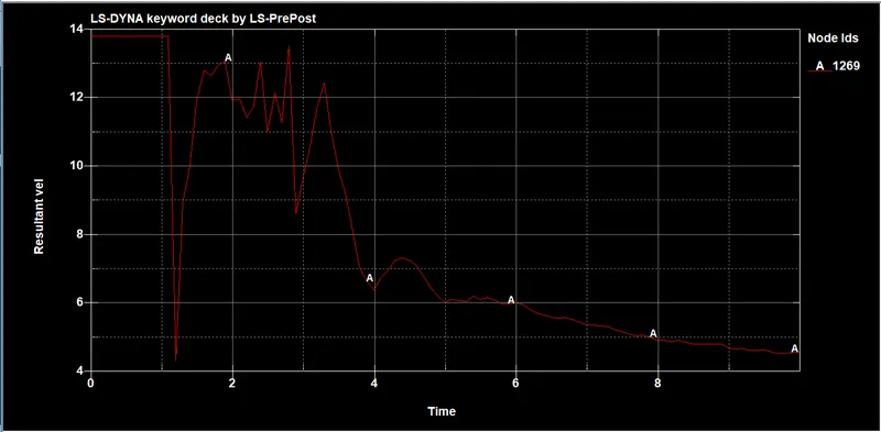
CRASH BOX WITH LOAD
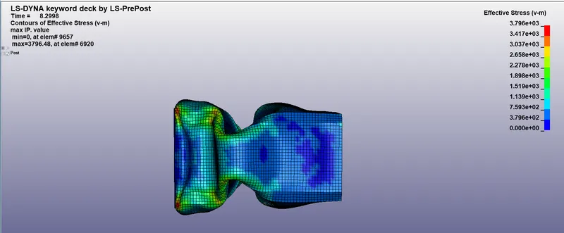
- The maximum von mises stress attained by the body is 379.6Mpa
- The yield strength of the material is 210MPa so that the component has undergone the plastic state.
- The material has undergone failure as per the theory of failure and we are observing the plastic behavior.
- So that the body will not come to its initial state.
- As the thickness of the component increases so that the stress developed is reduced it able to resist high forces.
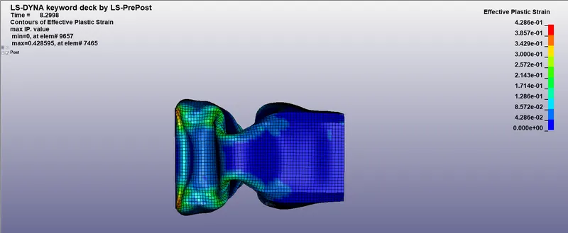
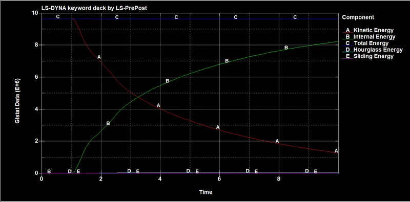
- As we can see that the component has contact with the rigid wall at 1.2 ms at that state the k.E decreasing and I.E is increasing.
- The total Energy attained in this component is 9.8e+06 N-mm.
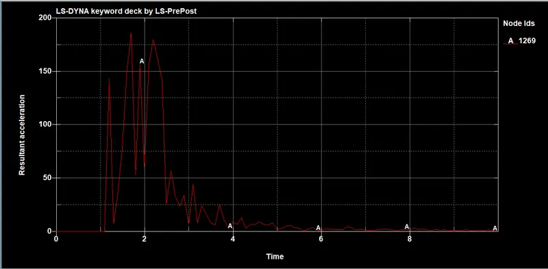
- As we can see that the acceleration is high at 2.3ms is 150 mm/ms^2
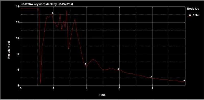
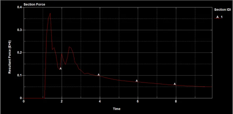
- From this graph, we can understand that the contact between the rigid wall and component happened at 1.2mm.
- From that force is started increases it reached 0.375e+06 N which is happened at 1.2ms at where the total force is been distributed.
| PROPERTY | THICKNESS | STRESS | TOTAL ENERGY | STRAIN | SEC FORCE |
| No crushing | 1.2mm | 350.602 | 107646 | 0.00757315 | 82298 |
| No crushing | 1.5mm | 343.64 | 134435 | 0.00712224 | 112040 |
| With crushing | 1.2mm | 4994.01 | 9.61E+06 | 0.441188 | 281530 |
| With crushing | 1.5mm | 3589.92 | 9.66E+06 | 0.428595 | 374360 |
CONCLUSION:-
- As we can see that as thickness is increased then the internal energy is increasing and there is a decrease in the stress
- And the force for the component has high sec force than the 1.2mm thick component there will be less chance for developing the strain.
- For the crushing component due to high mass, the stress is developed high
- We understood how to perform analysis and get output result from the solver