Week 4 - CHT Analysis on Exhaust port
Aim: CHT Analysis on Exhaust port.
Objective: The objectives will mainly focus on
- Give a brief description of why and where a CHT analysis is used.
- Maintain the y+ value according to the turbulence model and justify the results.
- Calculate the wall/surface heat transfer coefficient on the internal solid surface & show the velocity & temperature contours in appropriate areas.
- How would you verify if the HTC predictions from the simulations are right? On what factors does the accuracy of the prediction depend?
Introduction:
Conjugate heat transfer is a type of heat transfer analysis between solids and fluid(s). This type of heat transfer includes both convection (between fluids) and conductive (between solids) heat transfer, as well as both forced and natural convection. Common applications and use cases of this thermal simulation type include electronics cooling, heat exchangers, industrial machinery, some AEC cases, and more.
Conjugate heat transfer analysis can accurately predict heat transfer by simultaneous solving all the relevant solid and flow field heat transfer processes. Conjugate heat transfer corresponds with the combination of heat transfer in solids and heat transfer in fluids. In solids, conduction often dominates whereas in fluids, convection usually dominates. Conjugate heat transfer is observed in many situations for example: conduction through solids, free and forced convection in the gases/fluids and thermal radiation.
1.Pre-processing and solver setting:
Baseline mesh
- The geometry is opened into Space claim
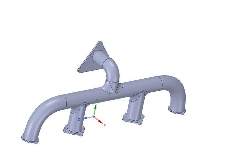
- The next step is extract the fluid volumes,
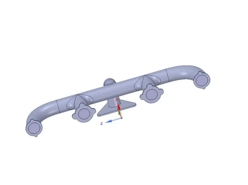
- Enable to share Topology
- Next step is click ''Overlap bodies''
2.Meshing:
After Overlap bodies see the mesh vertex arrangements,
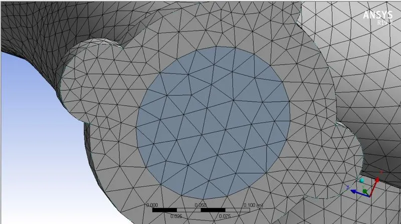
Create Name of the Individual part
Inlet :
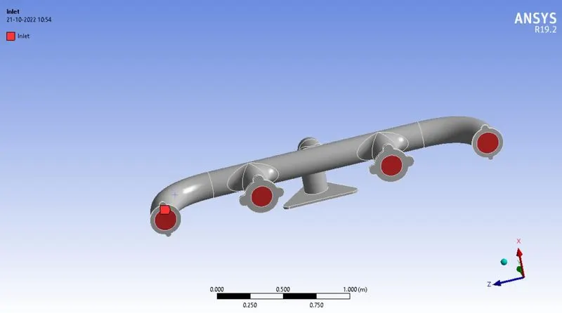
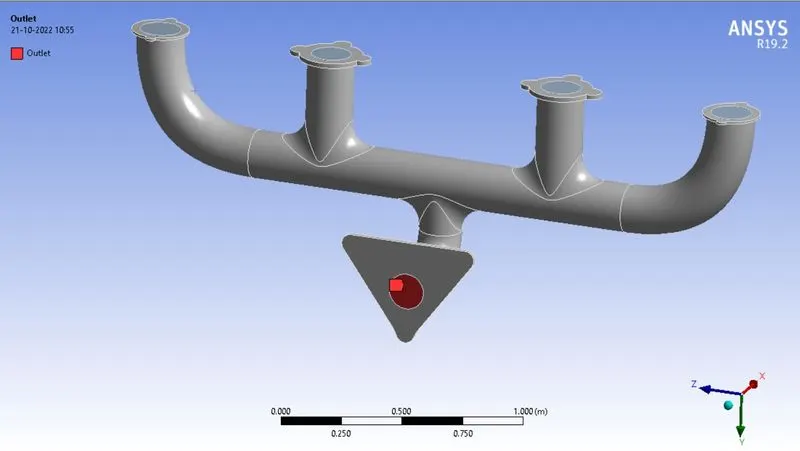
Outlet:
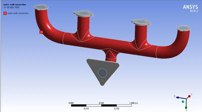
Outer wall convection:
Generate default mesh:
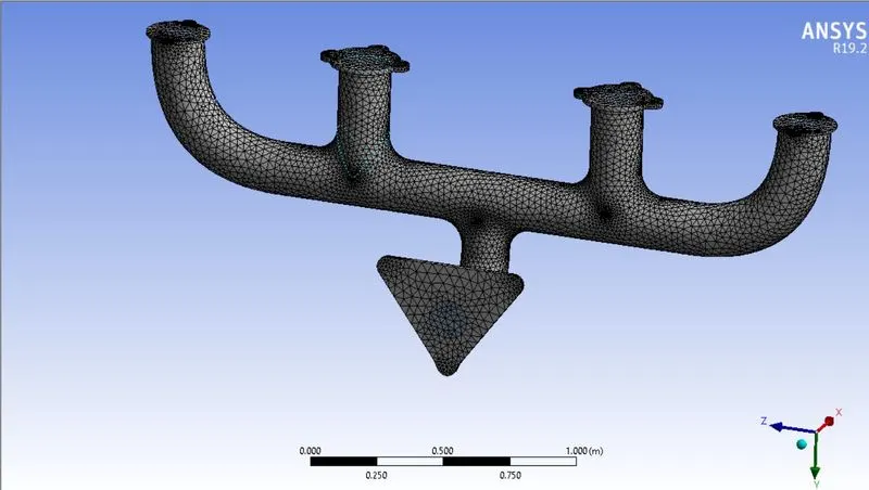
No of Elements: 138841
No of Nodes : 33782
Element Size : 0.15m
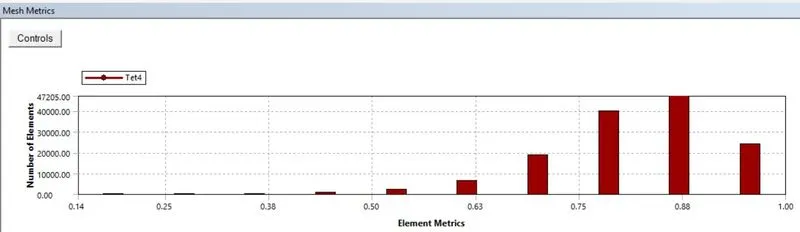
Mesh metrics:
3. Solution:
Physics:
The materials assigned for the fluid and solid are air and aluminum respectively.
Properties of air and aluminum:
Air:
| Density | 1.225 kg/m3m3 |
| Cp | 1006.43 J/kg K |
| Thermal conductivity | 0.0242 W/m K |
| Viscosity | 1.7894e-5 kg/m s |
Aluminum:
| Density | 2719 kg/m3m3 |
| Cp | 871 J/kg K |
| Thermal conductivity | 202.4 W/m K |
- Energy equation: It is turned on.
- Viscous model: It is set to k−ω SST
Boundary conditions:
The different boundary conditions are listed below
- Inlet boundary condition
- Type: Velocity inlet
- Velocity magnitude : 5 m/sec
- Temperature: 700 K
- Outlet boundary condition
- Type: Pressure outlet
- Gauge pressure: 0 Pa
- Outer wall convection
- Type: wall
- Thermal condition: convection
- Heat transfer coefficient: 20W/m^2 K
- The rest boundary condition values are set up as default values in ANSYS-FLUENT.
- Hybrid initialization is done. The simulation is run for 300 iterations.
Results:
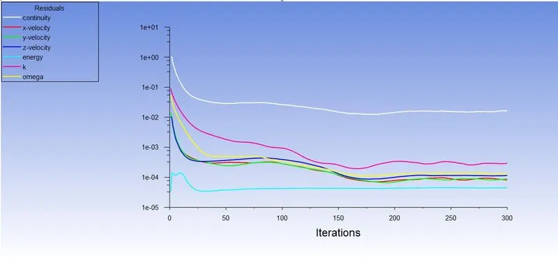
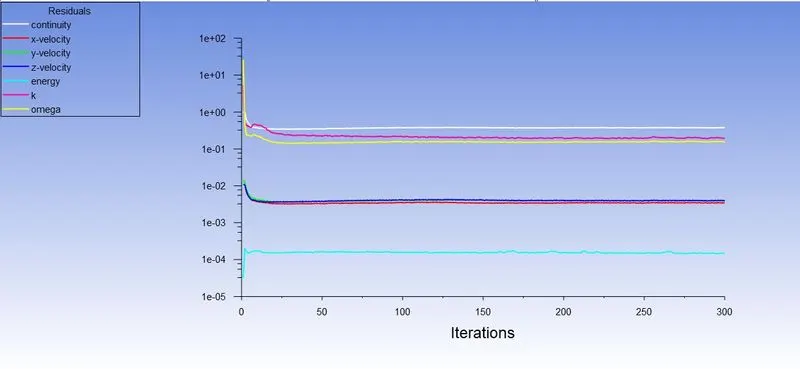
Residual plot:
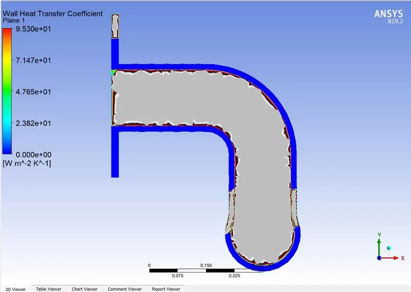
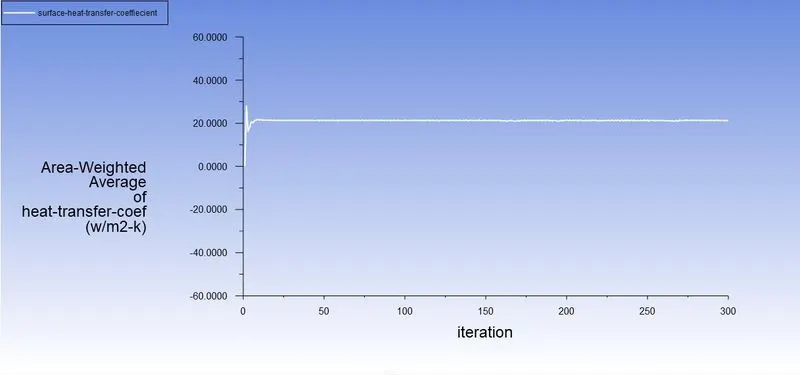
Surface Heat Transfer coefficient :
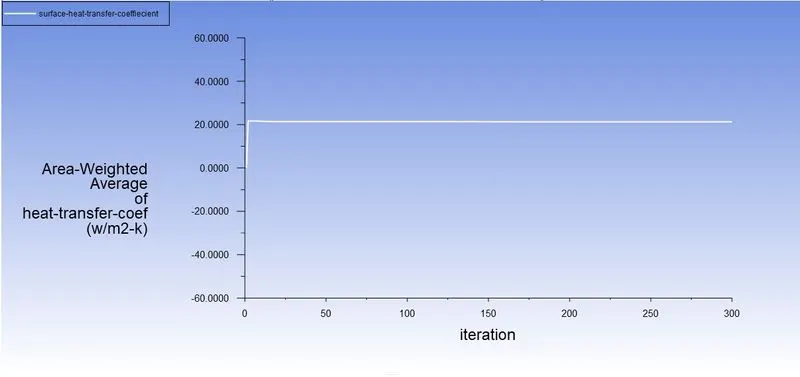
Surface heat transfer coefficient = 21.306477 W /m^2 K
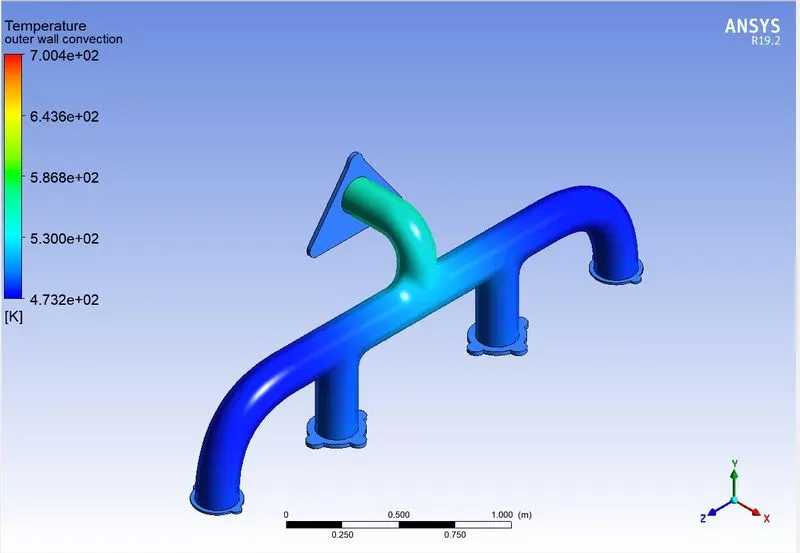
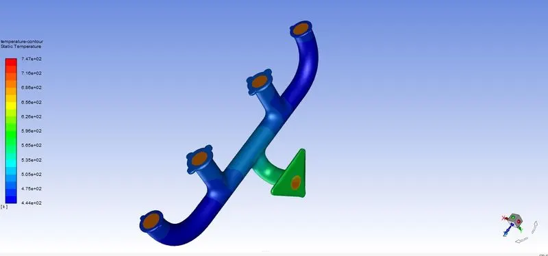
Temperature at outer convection wall:
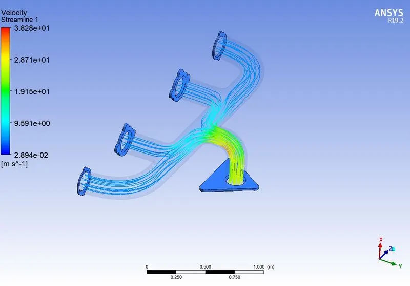
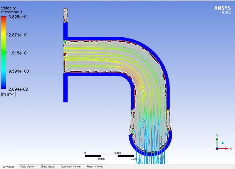
Streamline representation of velocity:
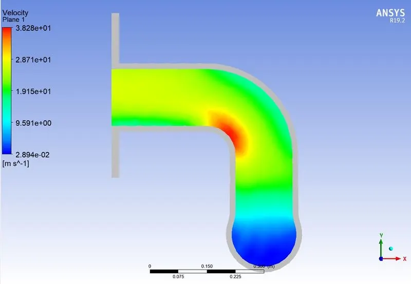
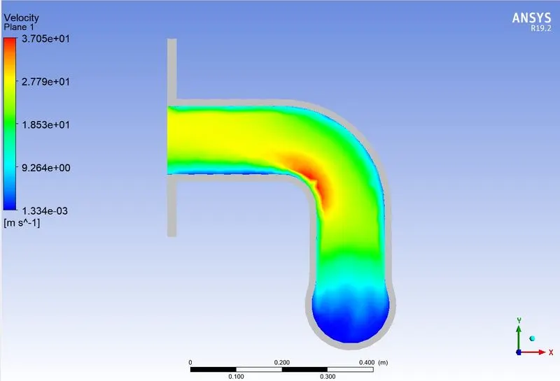
The velocity along plane-1 located at the exhaust section of the port:
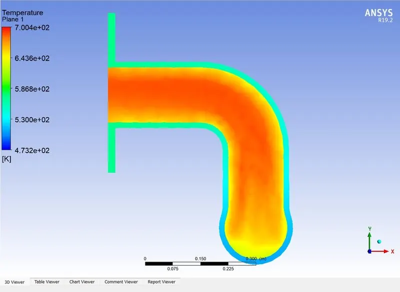
The Temperature along plane-1 located at the exhaust section of the port:
The heat transfer coefficient along plane-1 located at the exhaust section of the port:
The heat transfer coefficient with velocity streamline along plane-1 located at the exhaust section of the port:
CHT analysis of exhaust port with finer mesh:
First refinement:
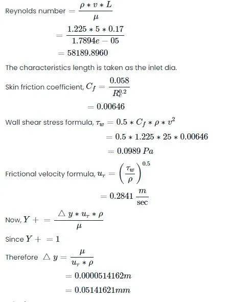
Calculating the first layer cell height:
Inflation
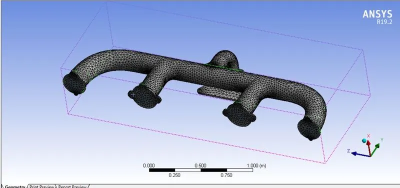
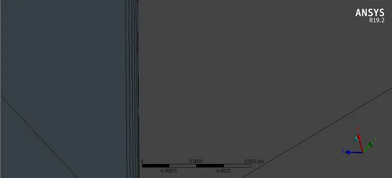
Number of inflation layer: 5
Growth rate: 1.2
Inflation option: First layer thickness
First layer thickness: =0.05141621mm
Captured curvature is set to yes.
Meshing:
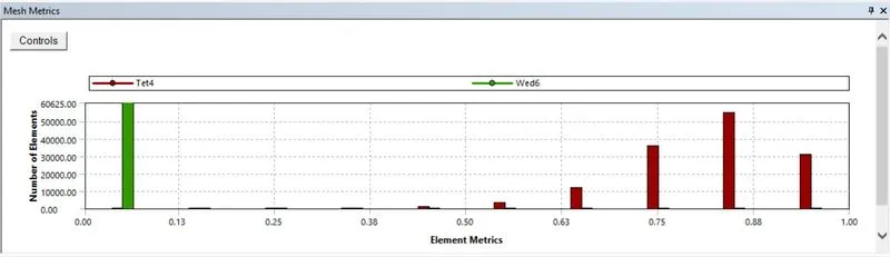
Mesh metrics:
Inflation Layer:
Results:
Residuals plot:
Heat Transfer coefficient Plot:
Temperature contour:
Velocity -Plane 1 - Contour:
Temperature-Plane 1 -Contour:
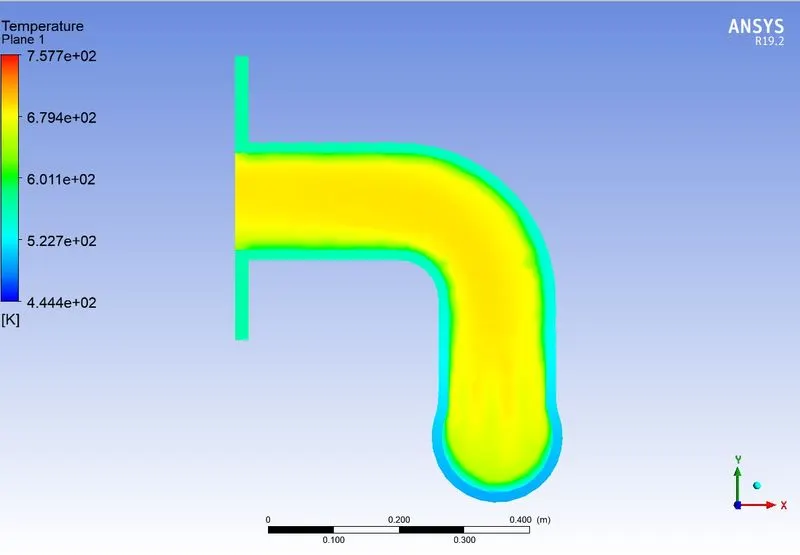
Heat Transfer Coefficient Contour:
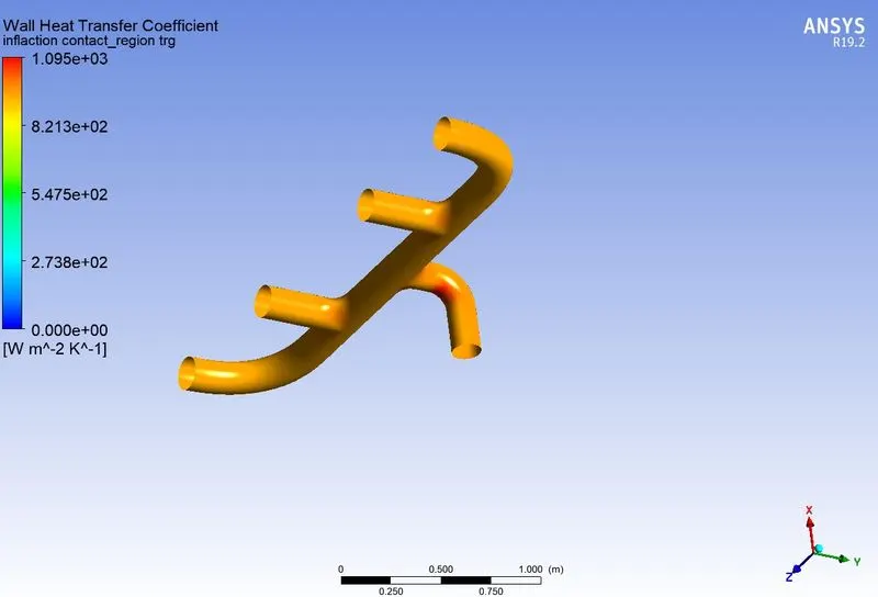
Mesh statistics and surface heat transfer coefficient
| Element size | 0.09 m |
| Number of elements | 195914 |
| Number of nodes | 63556 |
| Y+ | 1 |
| First cell height | 0.00005141620 m |
| Heat transfer coefficient |
21.505318 W / m2K |
Second refinement:
Element size: 50 mm
Number of inflation layer: 10
First layer thickness:0.05141621mm
Growth rate: 1.2
Meshing:
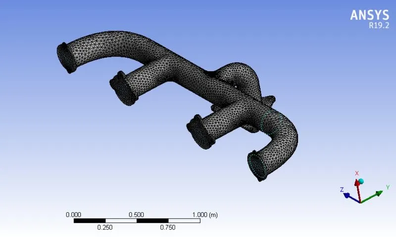
Mesh Quality:
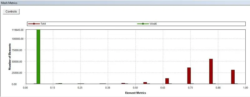
Results:
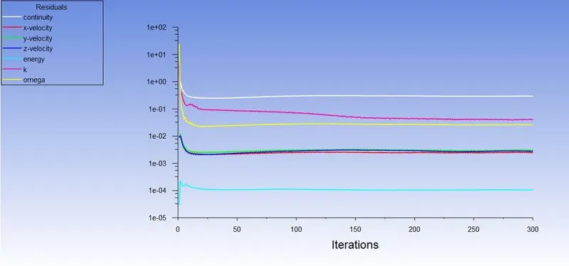
Residuals plot:
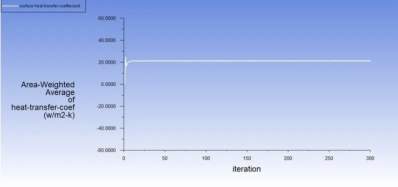
Surface heat transfer coefficient plot:
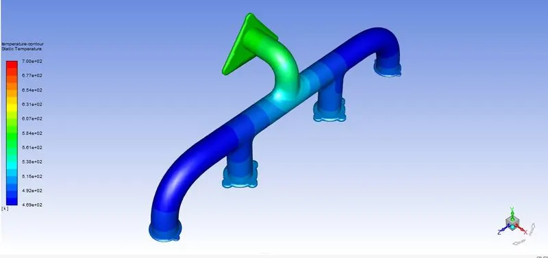
Temperature contour:
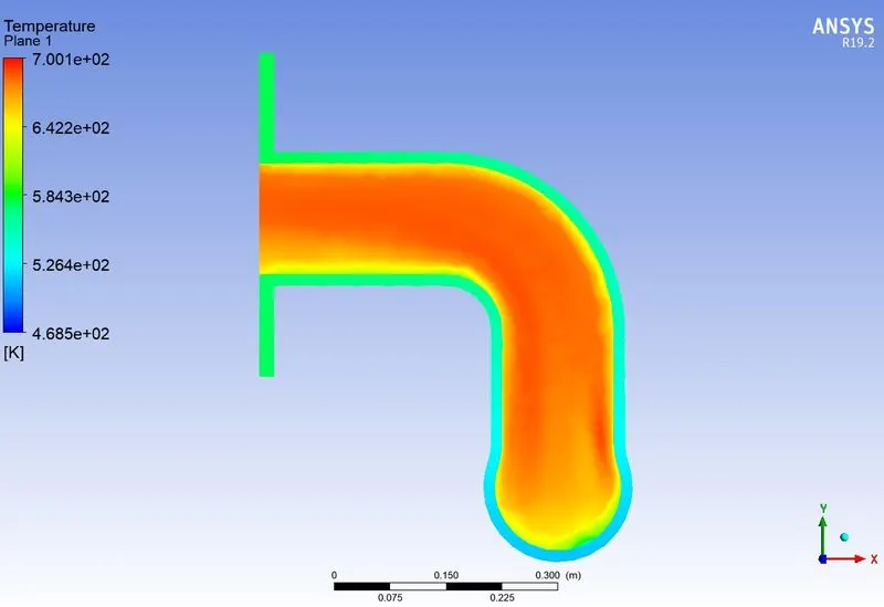
Temperature-Plane 1 - Contour:
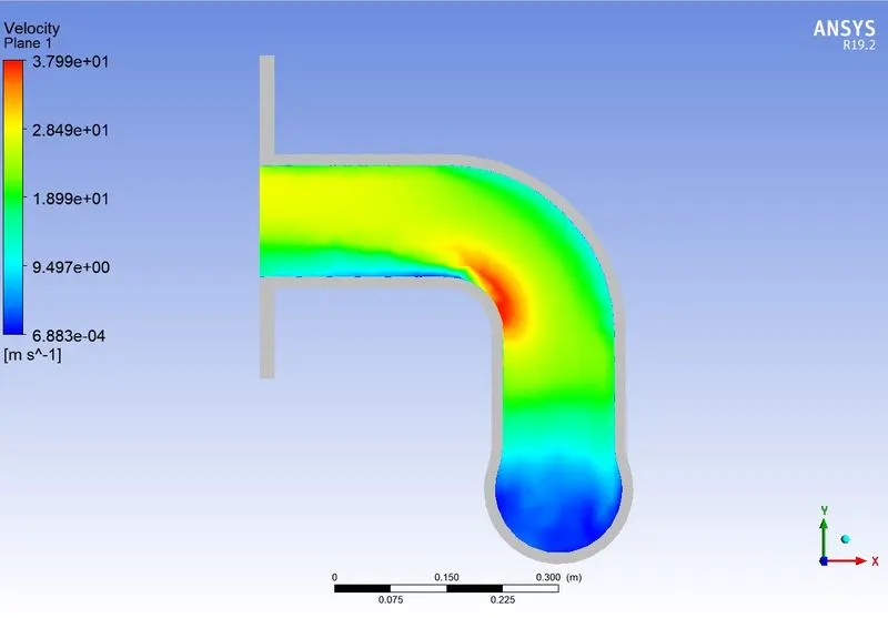
Velocity - Plane 1 - contour:
Mesh statistics and surface heat transfer coefficient
| Element size | 0.05 m |
| Number of elements | 255343 |
| Number of nodes | 93821 |
| Y+ | 1 |
| First cell height | 0.00005141620 m |
| Heat transfer coefficient |
21.664864 W / m2K |
Final refinement:
Element size: 10 mm
Number of inflation layer: 10
First layer thickness:0.05141621mm
Growth rate: 1.2
Meshing:
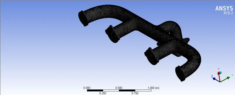
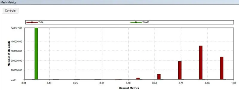
Mesh Quality:
Results:
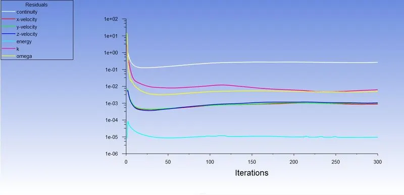
Residuals plot:
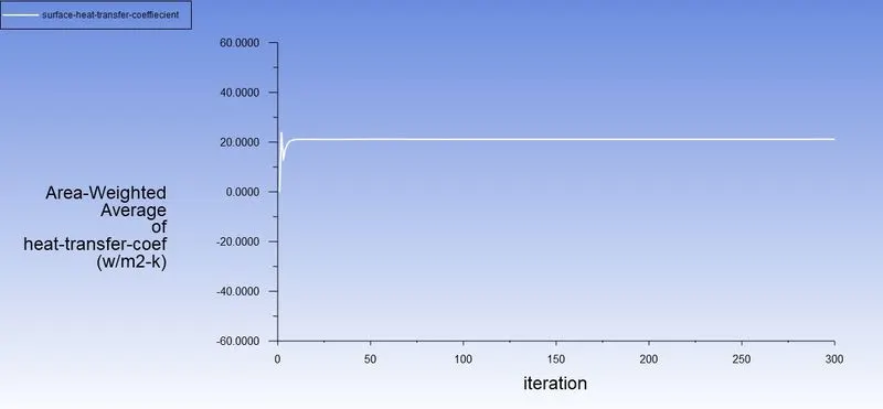
Surface heat transfer coefficient plot:
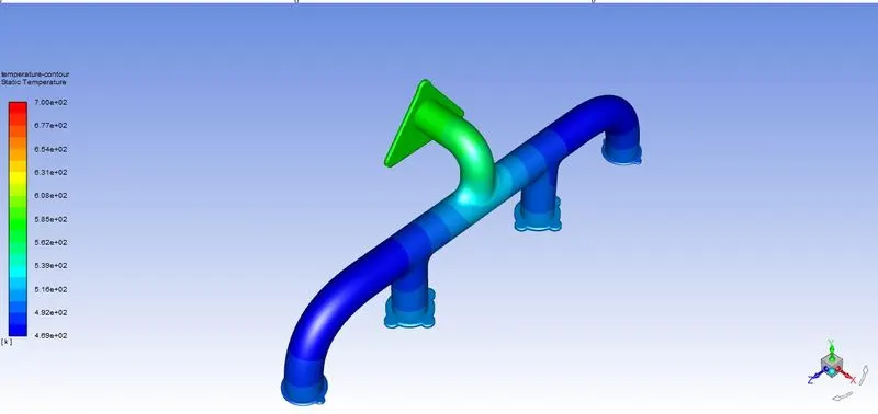
Temperature contour:
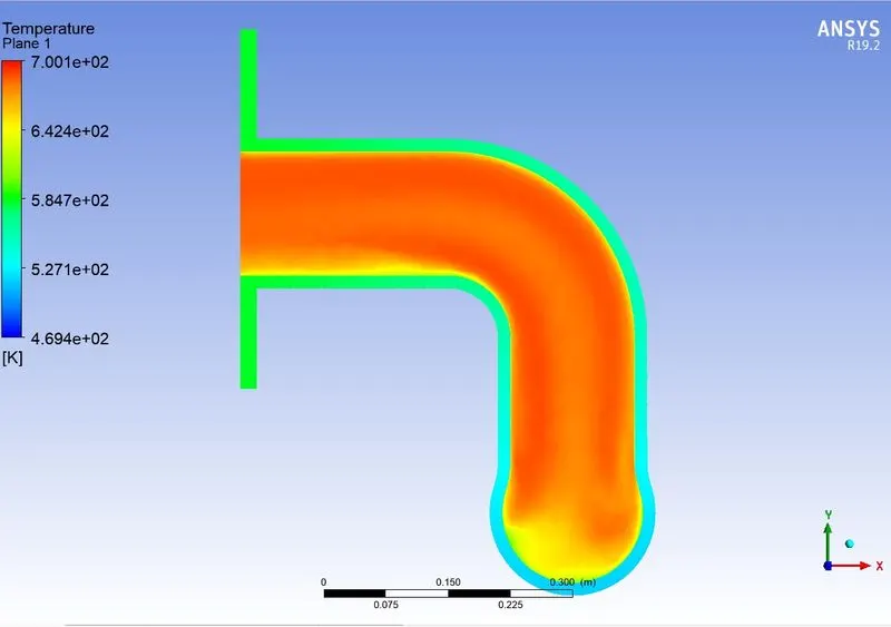
Temperature-Plane 1 - Contour:
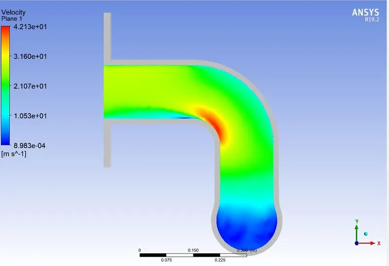
Velocity - Plane 1 - contour:
Mesh statistics and surface heat transfer coefficient
| Element size | 0.01 m |
| Number of elements | 1380939 |
| Number of nodes | 458722 |
| Y+ | 1 |
| First cell height | 0.00005141620 m |
| Heat transfer coefficient |
21.153098 W/m^2 K |
Analytical solution:
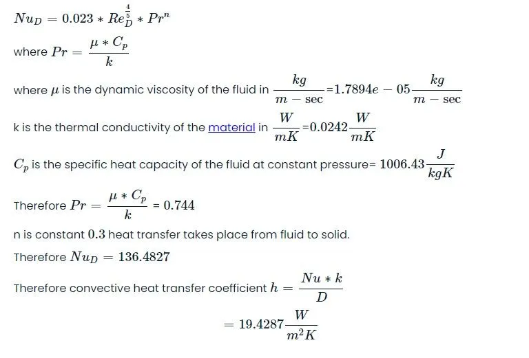
- The Reynolds number for the given flow is 58189.8960.
- Flow is turbulent in nature
- The Dittus Bolter heat transfer coefficient relation can be used to determine
the Nusselt number which is described mathematically as follows,
Comparison of all cases of Results:
| Element size | Number of elements | Number of nodes | First cell height | Y+ | Inflation layer | Surface heat transfer coefficient.(Numerical value) | Surface heat transfer coefficient. (Analytical solution) | Deviation | % Deviation /error % |
| 0.15m | 138841 | 33782 | N/A | N/A | N/A | 21.306477 W/m^2 K | 19.4287W / m^2 K | 1.8777 | 4.139 |
| 0.09m | 195914 | 63556 | 0.0000514162m | 1 | 5 | 21.505318 W/m^2 K | 2.076618 | 4.178 | |
| 0.05m | 255343 | 93821 | 10 | 21.664864 W/m^2 K | 2.236164 | 4.209 | |||
| 0.01m | 1380939 | 458722 | 10 | 21.153098 W/m^2 K | 1.724398 | 4.109 |
Conclusion:
- The CHT analysis on the exhaust port was simulated successfully on ANSYS-FLUENT.
- The pressure-based, coupled scheme solver is used to discretize the whole geometry.
- The analytical value of the heat transfer coefficient is 19.4287W /m^2 K.
- The all deviation of numerical heat transfer coefficient values from the analytical solution was found to be less than 5% .
- The grid independence test was also observed during mesh refinement. The value of the heat transfer coefficient for the final mesh refinement are close to each other. It is important that we limit ourselves to the final refinement only to save the computational time and cost of the project.
- The value of the heat transfer coefficient is located in the cell adjacent to the wall which allows us to choose the value of Y+=1 (viscous sublayer) and the turbulent model k−ω SST.
- The presence of the boundary layer is quite visible near the inlet of the pipe where the viscous force makes the velocity near the wall to be zero causing a no-slip condition to occur., but as the flow is turbulent in nature (Reynolds number = 58189.8960) the velocity profile goes from flat to the flutter and the boundary layer vanishes at the outlet.
- The velocity at the outlet is higher than the velocity at the inlet can be attributed to the presence of four inlets and one outlet.
- The accuracy of the heat transfer coefficient depends on selecting the suitable value of Y+ and turbulence model k−ω SST model.
- The heat transfer coefficient values predicted by CFD were validated against the numerical solution depicted the deviation in the range of less than 5% which is in compliance with industrial standards. However, the accuracy of k−ω SST model itself depends on the accuracy of the analytical solution, flow properties, and geometry. The values predicted by the baseline mesh and the refined mesh were close to each other this can be attributed to the fact that the boundary keeps on growing and declining from the inlet to the outlet owing to change in velocity, thus the value is predominant at the outlet section of the exhaust port.