Week - 4
- Implement control logic of a “washing machine” using Stateflow as per given sequence:
- If the power supply is available, the system gets activated
- If the Water supply is not available, stop the process & indicate through LED
- Soaking time should be 200s followed by Washing time of 100s.
- Then rinsing happens for next 20s & dryer runs for 50s
After all the processes have completed turn on the finished LED
Soln.
Stateflow is a graphical environment that allows you to design and simulate decision logic for supervisor control, task scheduling, and fault management applications.
Here is the simulink model of the given conditions:
#1 This image is after successful completion of given washing cycle:
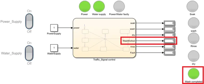
To impliment the given logic for 'washing machine' the followng simulink blocks are used
1. Rocker switch to control power supply and water inlet to the machine
2. Constatnt block to see the power and water supply status( On/Off)
3. Lamp to indicate different statuses as shown in the above image like Power supply health, water supply healthy, and power/water supply fail etc.
And lamps Soak, wash, rinse & dry glows only during the respective stage.
4. Display block connected to the chart indicating the same status as the lamps connected to it.
5. And a stateflow chart as shown bellow with diferent states and conditions to excecute them.
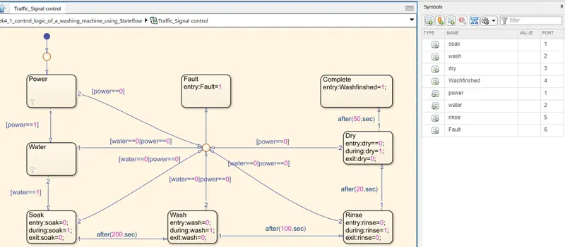
In the above stateflow logic, as per the assigned inputs and outputs using Symbols pane,
- First the chart verifies for power supply availability, if available it jumps to check for water availability otherwise terminates the process and gives power/water supply fail LED indication.
- If water avaialble then it goes for soaking & Soaking runs for 200sec. If either of water or power supply fails, process terminates and gives power/water supply fail LED indicaton.
Here we used 3 states : entry - to declare the initial state of the function
during - is used to give indication during the run timeof the state &
exit - is used to mention the state of the function while the state terminate
- after 200sec of soaking , jumps to Wash state and runs for 100sec (here also it checks for power or water supply fail and, if fail it leads to process termination and gives indiacaton
- After 100 sec, same process is repeated to terminate the process or to carryon next Rinse for nexf 20sec.
- after rinse dry or spinning state is excecuted for 50sec, while checking only for power fail as hereafter no need of water supply for washing. if no power, process terminates and gives indication
And after successful completion of 50sec Dry state, process is terminates to washfinshed state and gives LED indication
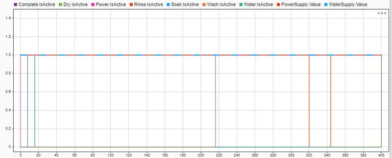
------------------------------------------------------------------------------------------------
#2 bellow image is the condition of water supply fail:
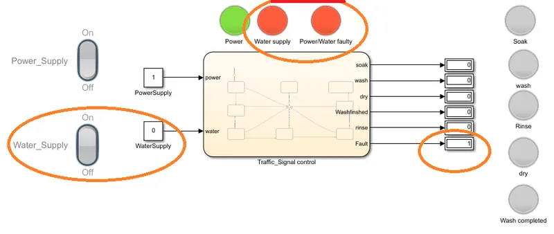
Image showing water Supply cutoff during washing state
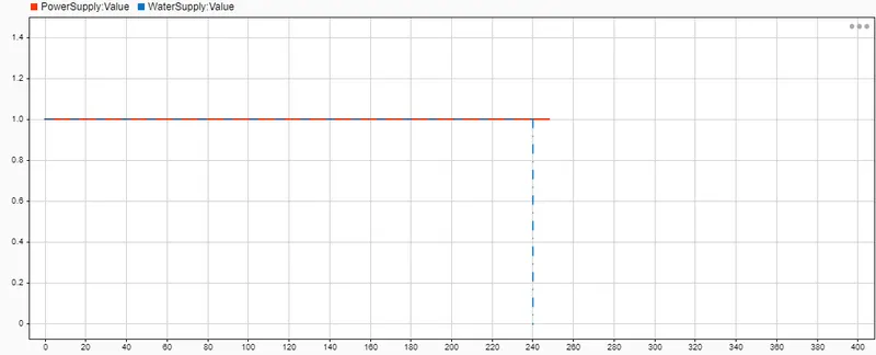
Following the input water supply fail, wash state immidiately terminated and given a fault signal indiaction as shown in bellow image
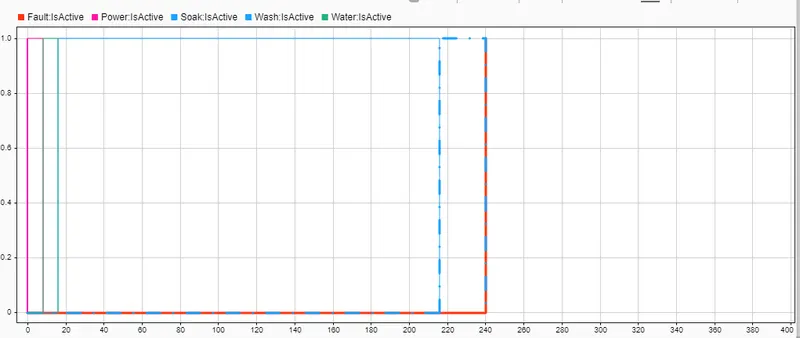
.........................................................................................................................................................
2. Make a Simulink chart for the “Gear shift” logic as per below conditions:
Speed Range(kmph) Gear
0 to 15 1
16 to 25 2
26 to 40 3
41 to 60 4
Above 61 5
Give speed input while the simulation is running & display the gear number.
Soln.
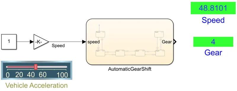
Here is the sateflow model for the given gear shift logic, utilising the following block
1. Slider gain for varying the vehicle speed while simulation is running
2. Gain block and Constant block connected to slider gain block all together connected as Speed input to the stateflow chart
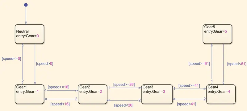
#Here is the stateflow chart with the different states for given speed limits and respective gears
Entry of each Gear state (1-5) including neutral is set according to the given speed range as shown in bellow chart
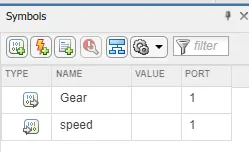
In symbols pane speed from the is set as input and Gear number as output.
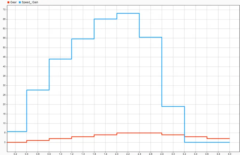
In the following plot, we can observe vehicle speed in blue colur and Gear position which is in response to the varying speed in red colour
Stateflow models files for the above two cases is attached