Week-11 Challenge: Braking
- For a defined driving cycle, calculate the energy required for braking
Soln:
A Driving Cycle is a series of data points representing the speed of a vehicle versus time.
Driving cycles are produced to assess the performance of vehicles in various ways, as for instance fuel consumption, electric vehicle autonomy and polluting emissions. There are several diiferent types of driving cycles available and for our calculation we consider Urban Dynamometer Driving Schedule (UDDS)
Vehicle Braking :
The function of the braking system is to reduce the speed of the moving vehicle or bring it to rest in the shortest possible distance whenever required.There are several techniques to apply brakes, which can be mechanical or electrical. The most commonly used technique is by applying friction.
The brakes must be capable of decelerating a vehicle at a faster rate than the engine is able to accelerate it. Kinetic energy is the force that keeps the vehicle moving. This energy is provided by the engine in order to accelerate the vehicle from a standstill to desired speed. Kinetic energy is dissipated as heat by the brakes during application of breaks.
The kinetic energy of a vehicle during braking is given by
Braking Energy = (1/2)*m*v^2
Where, Braking Energy is the kinetic energy in unit of Joule.
m= Total Mass of the Vehicle (Vehicle Mass + Pay Load) in unit of Kg.
v= (Initial Velocity-final Velocity) in unit m/s.
Energy required for braking :
There are several diiferent types of driving cycles available and for our calculation we consider Urban Dynamometer Driving Schedule (UDDS).
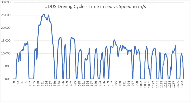
For ease of calculations, here we considered upto first 150sec of the UDDS driving cycle and braking energy for this duration is calculated as shown in bellow image.
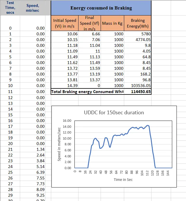
From the above calculations (Excel sheet attached), for 1st 150 Sec of UDDS Drivng cycle, it takes 114.45kWh of energy.
2.Why electric motor can’t develop braking torque at high speed similar to starting? How electric and mechanical brakes are coordinated?
Ans:
During statring of an electric motor in Electric Vehicle, the staring speed is low and we will get high torque values during starting as speed and torque are inversely related. When we gradually increases the speed, torque developed by the motor decreases.
During Braking the motor is already at high speed and we are going to apply friction based mechanical brakes &/ regenrative braking. Here we operating the motor in field weakening region or above base speed of the motor, so the torque developed is compramised (torque value is less).
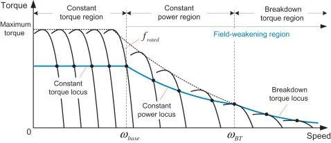
The operation range of an induction motor can be divided into three regions according to the output torque capability as:
-
1. Constant torque region: speed range below the base speed
-
2. Constant power region: speed range above the base speed
-
3. Breakdown torque region: speed range above the base speed maintaining the maximum slip frequency
The speed range above the base speed can be further divided into two subregions: constant power region and breakdown torque region. Because the field flux is reduced for operation in these regions, they are called field-weakening regions.
Electric and mechanical brakes coordination:
Mechanical Brakes are usual friction based or hydraulic cylinder based brakes and electric brakes are (i) Rheostatic or dynamic braking, (ii) Plugging or reverse current braking and (iii) Regenerative beaking.
We have Different Brake Control Strategies:
1. Series - Mechanical and regenerative brakes are applied one after the other
Series braking is further classified based on drivers comfort level and energy efficiency
2. parallel - Both mechanical and regenerative brakes applied at same time
With adavancements in control systems, we have EDIB (Electrically Driven Intelligent Braking)
EDIB is a combination of hydraulic brake or mechanical brake along with the regenerative barking.
In this control signal from brake pedal is provided to both hydraulic brake and regenerative brake which is then to power converter.This we call as Regenerative coopereative braking control
at High speeds - i.e, initial braking period, we apply both brakes through control signals
at Low speeds - % of regenrative braking applied is predominant than mechanical/hydraulic brake.
When the braking force demanded is less than the maximum braking force that the electric motor can produce,only electrically regenerative braking will apply.
When the commanded braking force is greater than the available regenerative braking force, the electric motor will operate to produce its maximum braking torque, and the remaining braking force is met by the
mechanical brake system.
3.Make a MATLAB program which plots contour of given motor speed, torque and efficiency values. Attach the code as a .m file attach a screenshot of all the plots.
Ans.
For any motor , Total power input = Total losses+Output power
Know all the losses in an electric motor:
A Motor have various types of losses happening inside. The various types of losses are
Copper Losses - I^2⋅R, where R is the Armature resistance and we say that Torque is proportional to Current, this copper loss can be consider as kc⋅T^2.where kckc is to take care of resistance of brushes and also take care of flux and its effect.
Copper losses = kc⋅T^2
Iron Losses - Iron Losses are nothing but Magnetic losses, which is denoted as ki⋅ωki⋅ω, where kiki factor is based on the Magnetic field effect. For Permanent Magnets have constant Magnetic field and this Iron losses is based on the value of kiki and this are going to change according to the Speed. At Various Speed have different value of Back EMF and that is going to affect the Iron Losses.
Iron Losses = ki⋅ω
Windage Losses - This is a Mechanical or friction of Windage losses. This is based on size of shape of Motor and the amount of windage losses that the motor is going to experience.
Windage Losses = kw⋅ω^3
Constant Losses - This is denoted as C.
Total Losses - The Total Losses are considering the above four losses and denoted as,
Total Losses = kc⋅T^2 + ki⋅ω+ kw⋅ω^3 + C
All Motors are model as per the above equation of losses. This above equation is not only applicable for Permanent Magnet DC Motor, but other motors as well like induction motor
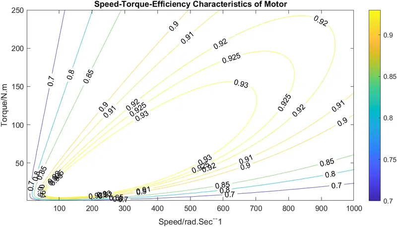
Contour plot is the representing data in X,Y and Z axis
Here below is the MATLAB code for plotting motor Speed-torque- efficiency as a contour plot
% A program Plotting an electric motor spped-torque-efficiency contour

X=linspace(1,1000);  %motor speed in rad/s not rpm
Y=linspace(1,250);   %Torque N-m

% AllocateMotor loss constant
Kc=0.2;     %for copper loss
Ki=0.008;   % for Iron losses
Kw=0.00001; % for windage losses
ConL=20;    % for constatnt motor losses

% now make mesh
[X,Y]=meshgrid(X,Y);
OutputPower=(X.*Y);  % Power=Torque*Speed
B=(Y.^2)*Kc;         % Copper losses
C=X*Ki;              % Iron losses
D=(X.^3)*Kw;         % windage losses
InputPower=OutputPower+B+C+D+ConL;
Z=OutputPower./InputPower; % efficiency of the motor

% we now set the efficiency for which a contour will be plotted
V=[0.7,0.8,0.85,0.90,0.91,0.92,0.925,0.93];
box off
grid off
contour(X,Y,Z,V,'ShowText','on');
title('Speed-Torque-Efficiency Characteristics of Motor');
xlabel('Speed/rad.Sec^-^-1');
ylabel('Torque/N.m');
Output Contour plot for the above code is:
matlab script file is attached.