Project 2
Using MATLAB/simulink and the drive cycle from the attached excel sheet, find-
- The max heat generation of the battery
- The SOC of the battery at 2 *104second of the battery operation
| Time | Time Step | Battery Current |
| 00:00.4 | 0.1 | -0.9632 |
| 00:00.5 | 0.2 | -0.952 |
| 00:00.6 | 0.3 | -0.9072 |
| 00:00.7 | 0.4 | -0.9632 |
| 00:00.8 | 0.5 | -1.0304 |
| 00:00.9 | 0.6 | -0.9632 |
| 00:01.0 | 0.7 | -1.0304 |
| 00:01.1 | 0.8 | -1.008 |
| 00:01.2 | 0.9 | -0.9856 |
| 00:01.3 | 1 | -0.9632 |
| 00:01.4 | 1.1 | -0.9184 |
| 00:01.5 | 1.2 | -0.9296 |
| 00:01.6 | 1.3 | -0.9296 |
| 00:01.7 | 1.4 | -0.9296 |
| 00:01.8 | 1.5 | -0.9184 |
| 00:01.9 | 1.6 | -0.9408 |
| 00:02.0 | 1.7 | -0.896 |
| 00:02.1 | 1.8 | -0.9072 |
| 00:02.2 | 1.9 | -0.9072 |
| 00:02.3 | 2 | -0.9408 |
| 00:02.4 | 2.1 | -0.9296 |
| 00:02.5 | 2.2 | -0.9296 |
| 00:02.6 | 2.3 | -0.9968 |
| 00:02.7 | 2.4 | -0.9968 |
| 00:02.8 | 2.5 | -0.9408 |
| 00:02.9 | 2.6 | -0.9408 |
| Battery resistance | 2 milli ohm |
Consider the battery resistance is 0.5 mOhm, delta time is 0.1 and entropic factor is 2
Aim:
To calculate the maximum heat generated by the battery and also to calculate th SOC of the battery pack at 2*104second if the battery operation for the given drive cycle data by using MATLAB and SIMULINK tools.
Theory
Heat Generation in Batteries:
Heat generation is a significant issue in battery operation, as excessive heat can lead to thermal runaway and reduce the battery's lifespan.
Heat is generated in batteries due to various factors, including internal resistance, charging and discharging rates, and ambient temperature. Higher resistance leads to more heat generation, which in turn causes more degradation of the battery. Fast charging and discharging rates also generate more heat, as the battery's chemical reactions occur more rapidly. Additionally, high ambient temperatures can also increase heat generation in batteries.
To mitigate heat generation, battery manufacturers often use various cooling techniques, such as air or liquid cooling. Active cooling methods use external components to cool the battery, while passive cooling methods rely on the battery's natural heat dissipation.
SOC stands for State of Charge, which is a measure of the amount of energy stored in a battery at a specific point in time, expressed as a percentage of the battery's total capacity. SOC is an important parameter for managing battery systems as it helps to determine the available energy in the battery, which is critical for estimating the range of an electric vehicle or the remaining runtime of a portable device. Accurate SOC estimation is essential for ensuring the safe and efficient operation of battery systems, as overcharging or deep discharging can cause irreversible damage to the battery and reduce its lifespan.
SOC Estimation Techniques:
SOC estimation is a crucial aspect of battery management, as it helps prevent overcharging and over-discharging, which can damage the battery. There are several techniques for estimating SOC, including:
1.Coulomb Counting: Coulomb counting estimates SOC based on the amount of charge flowing in and out of the battery. This method is relatively simple, but its accuracy can be affected by measurement errors and changes in battery capacity over time.
2. Open Circuit Voltage (OCV) Method: The OCV method estimates SOC based on the voltage of the battery when it is at rest. The method assumes that there is a linear relationship between SOC and OCV, but this relationship can be affected by temperature and other factors.
3. Kalman Filters: Kalman filters are mathematical algorithms that use a combination of measurements and predictions to estimate SOC. This method can be accurate, but it requires complex programming and significant computational power.
4. Model-Based Estimation: Model-based estimation uses a battery model to estimate SOC based on current and voltage measurements. This method can be highly accurate, but it requires a detailed understanding of the battery's behavior and a robust model. In summary, heat generation and SOC estimation are critical aspects of battery management, and there are several techniques available to mitigate heat and estimate SOC accurately.
Calculation:
1.
In a battery system, the two sources of heat generation are Joule heating and entropy heating.
Joule heating is generated due to the resistance of the electrodes and the electrolyte. The power dissipated due to Joule heating can be calculated using the following equation:
P = I^2 * R
Where P is the power dissipated, I is the current flowing through the cell, and R is the resistance of the cell.
Entropy heating, also known as chemical heating, is generated due to the irreversible chemical reactions in the cell. The entropy heat generated can be calculated using the following equation:
Q = T * ΔS
Where Q is the entropy heat generated, T is the temperature of the cell, and ΔS is the change in entropy during the reaction.
The total heat generated in the cell is the sum of the Joule heating and entropy heating. It is important to monitor and manage the heat generated in the battery system to prevent overheating and damage to the cells.
Given data
- Considering Battery resistance = 0.5 mOhm = 0.0005 Ohm
- DeltaTime =0.1,
- Entropy factor =2
Maximun current = 1.0304 A
Max current at time 0.5 & 0.9 sec , time step = 0.1
Entropic factor = 2
The maximum heat generation in the battery pack
Max heat generation = Max Joule Heat + Entropy heat
The formula for calculating the heat generated is:
Heat Generated = (Battery Current^2 x Battery Resistance x time step)+( Delta Time x Entropic Factor)
Max Joule Heat = I^2 *R*t
Max Joule Heat = (1.0304^2) * 0.0005* 0.1
Max Joule Heat = 0.05 mJ
Entropy heat =ΔT* entropy factor = 0.1 * 2= 0.2 J
Max heat generation = 0.05 + 2 = 0.20005 Jouls
The Max heat generation is 0.20005 Joules
2. The SOC of the battery at 2 *104second of the battery operation:
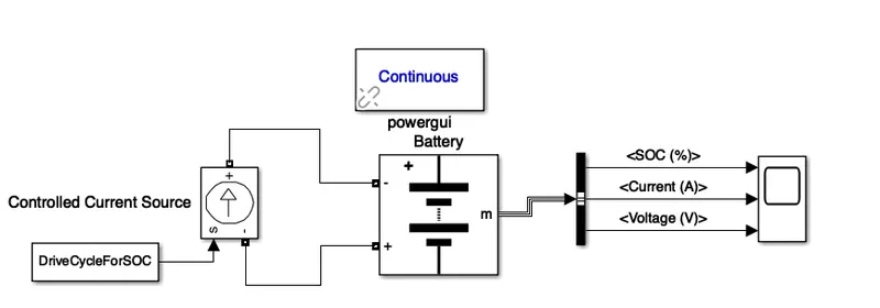
For the simulation model following blocks are used
- Generic Battery - Implements a generic battery model for most popular battery types. Temperature and aging (due to cycling) effects can be specified for Lithium-Ion battery type.
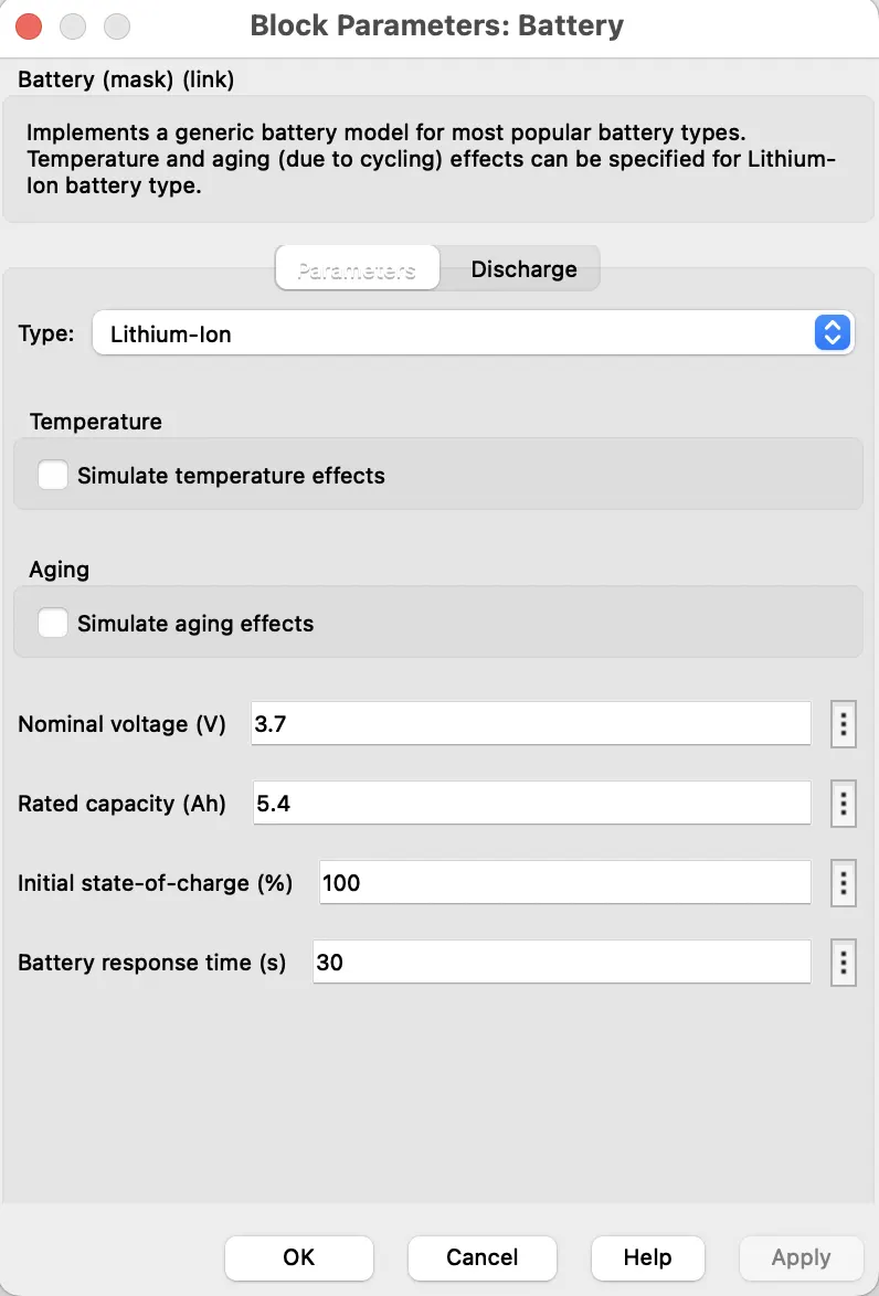
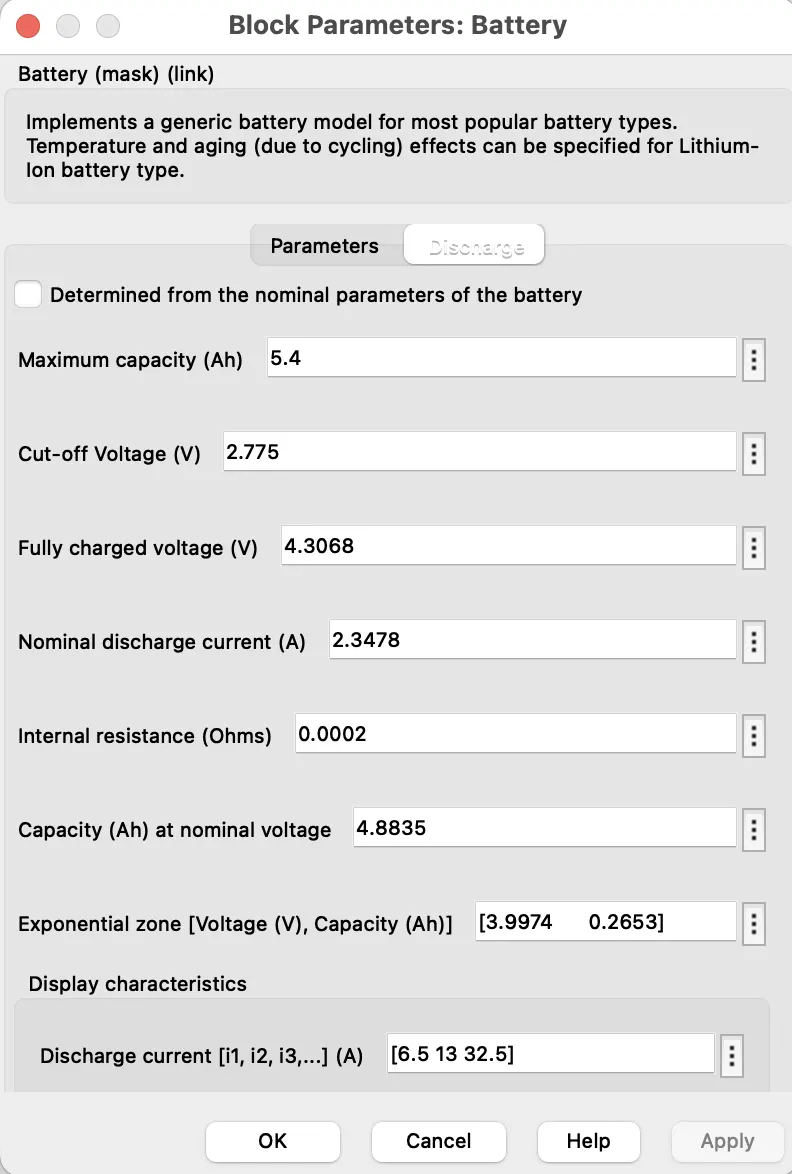
- Controlled current source - Converts the Simulink input signal into an equivalent current source. The generated current is driven by the input signal of the block.You can initialize your circuit with a specific AC or DC current. If you want to start the simulation in steady-state, the block input must be connected to a signal starting as a sinusoidal or DC waveform corresponding to the initial values.
- Bus Selector -This block accepts a bus as input which can be created from a Bus Creator, Bus Selector or a block that defines its output using a bus object. The left listbox shows the elements in the input bus. Use the Select button to select the output elements. The right listbox shows the selections. Use the Up, Down, or Remove button to reorder the selections. Check 'Output as virtual bus' to output a single bus.
- From workspace-To input the given battery current data repeadetly for 208 sec
- Scope- to Display the output graph
- Powergui -Set simulation type, simulation parameters, and preferences.
Conclusion:
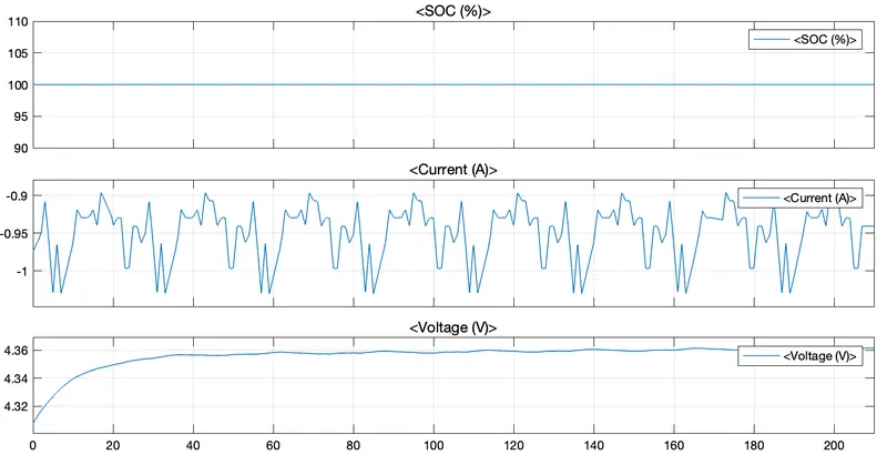
The Max heat generated in which the current flowing in and out i.e., charge and discharge due to internal resistance and chemical reaction during charging and discharging of the battery the heat is generates of 0.20005 Joules
And also we observed the SOC for 208sec for the given drive cycle.