Week-6 Challenge: EV Drivetrain
1. Which types of power converter circuits are employed in electric and hybrid electric vehicle?
Available PEC(Power Electronoc Converters) in EV/HEV that includes
DC/DC converters(Choppers),
DC/AC rectifiers ,
AC/DC inverters,
AC/AC Regulators
and battery charger composed of AC/DC and or DC/DC converters .
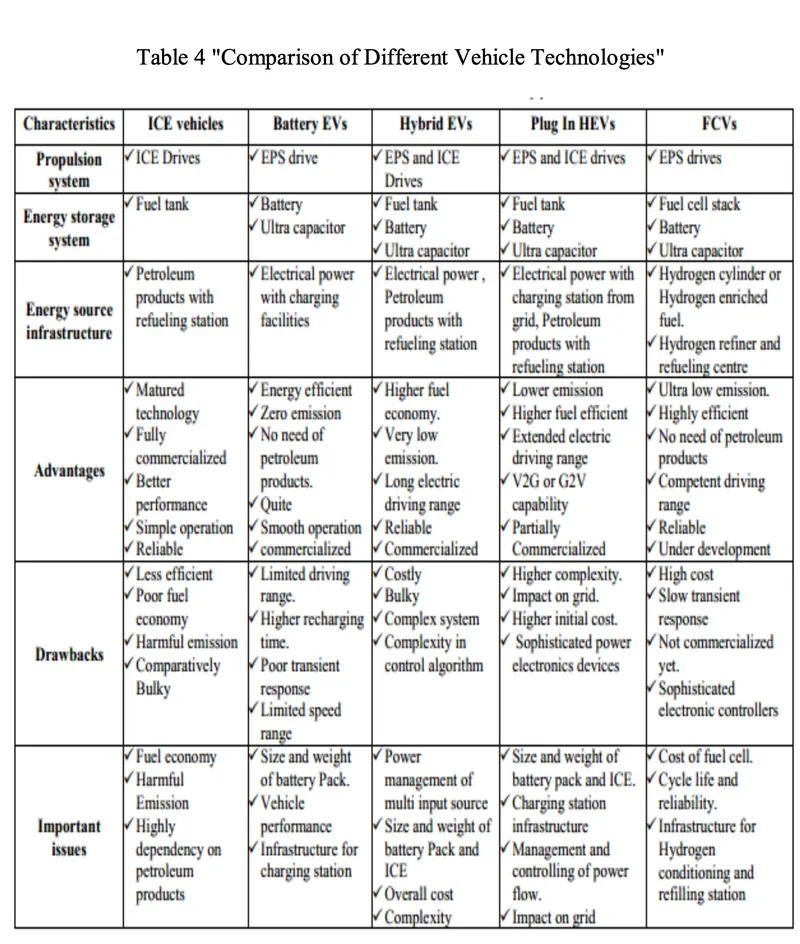
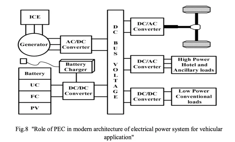
Individually or combination of these converters can be taken to serve the purpose; however, operation of each PEC is entirely different from the other. PECs perform some of the critical tasks like ON/OFF switching of various loads; power conditioning and voltage/current modulation to create compatibility among the energy source system (ESS), traction motors and auxiliary loads.
PECs not only serve the purpose of converting electrical power from one form to another (DC/DC, DC/AC and, AC/DC) but also help to step up or step down the system voltage level.
 ____________________________________________________________________________________
A) DC/DC Converters :
A DC/DC converter in its basic form converts unregulated DC input voltage at a certain level to a regulated DC output voltage at a different level with very high conversion efficiency (>90%). Modern day DC/DC converters are operated at high frequencies (10 kHz - 1 MHz). The size of the components such as inductors, transformers, and capacitors are reduced at high frequency operation. Transistors such as MOSFETs and IGBTs are used as switches. The former is preferred in high frequency, low and medium power applications, whereas the latter is preferred in low frequency high power applications. The switches are turned ON and OFF by pulse- width modulation (PWM) technique
From the architecture of the HES(HYBRID ENERGY SYSTEMS), the DC/ DC converters used in EVs may be used for:
1. Providing low voltage (12V or 14V) for low voltage loads.
2. Boosting the voltage level of the battery such that it matches the level of the DC bus voltage for driving the AC motor inverter if the traction motor is AC motor.
3. Motor propulsion if the traction motor is a DC motor.
A1. DC/DC Converters used for supplying Low Voltage Loads (12-14V):
Several types of converters are available with characteristics which make different converters suitable for different applications. These converters include
1.PWM DC/DC Converters
2.Quasi-Resonant Converters
3.Zero-Voltage-Switched Multi-Resonant Converters
4.Constant-Frequency Quasi-Resonant and Multi-Resonant Converters
5.Non-Linear Resonant Switch Converters
6.Resonant Converters
7.Soft-Switched PWM Converters
8.Zero-Voltage-Switched/Zero-Current-Switched PWM Converters
Recently, soft-switched PWM converters have been gaining popularity in the power supply industry.
A2. DC/DC Converters used for boosting the battery voltage:
AC motors in EVs and HEVs are fed by inverters which in-turn is fed by a high voltage DC/DC converter. As an example, in Toyota Prius the low voltage bus is at 201.3 V Nickel-Metal Hydride (Ni-MH) battery output, which is converted to 500 V by a simple boost converter to feed a 50KW (1200-1540 rpm) PMSM. This arrangement is shown in Fig.
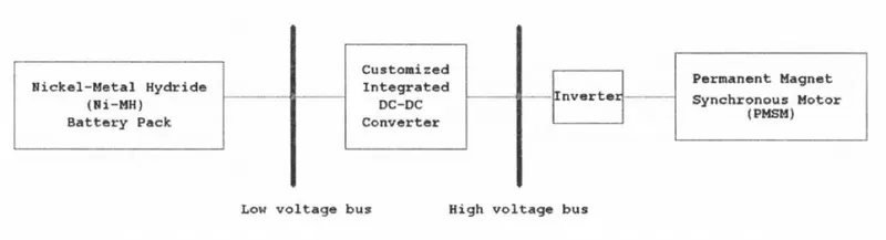
"Role of DC/DC converter in voltage boosting"
1. Non-isolated Bidirectional Half Bridge DC/DC Converter
2.Isolated Bidirectional Full Bridge DC/DC Converter (IBDC).
3.Isolated Bidirectional Dual Half Bridge DC/DC Converter.
4.Interleaved DC/DC Converter
A3. DC/DC Converters used for DC Motor Drives:
1.Two-Quadrant Zero-Voltage-Switching Multi-Resonant (2Q-ZVS-MR) Converter
2.Two-Quadrant Zero-Voltage-Transition (2Q-ZVT) Converter
3.Two-Quadrant Zero-Current-Transition (2Q-ZCT) Converter
B) DC/AC Converters:
A suitable DC/AC inverter draws DC power from the batteries to drive the electric traction motor, which in turn provides power to the wheels. The DC/AC inverter also performs the function of recharging the batteries during regenerative braking in HEVs. Also, Inverters are used for supplying utility loads such as Air conditioning and power outlets. Inverters are generally classified into voltage-fed and current-fed types.
The output waveform of an inverter may be rectangular, six–step or pulse width modulation (PWM), depending on the switching strategy for different applications. For example, a rectangular output waveform is produced for a PM brushless DC motor, while a six–step or PWM output waveform is for an induction motor.
B1. H-Bridge Topology with Single DC link
B2. Soft-Switching Inverters :
a). Resonant DC link Inverter
b). Auxiliary Resonant Commutated Pole Inverter
c). Auxiliary Resonant Snubber Inverter
d). Zero Current Transition Inverter
B3. Multilevel Inverters :
a). Cascaded H-Bridge Multilevel Inverter
b). Back-To-Back Diode Clamped Multilevel Inverter
c). T-Type Five Level Converter
B4. Impedance Source Inverter (ZSI):
C) AC/DC Converters:
Charging may be classified to three types.
Level (1) is the slowest method. It uses a standard 120V/15A single phase grounded outlet. It is used for home or business sites and low off-peak rates are likely to be available at night. It usually takes from 4-11 hours.
Level (2) charging requires 240V outlet, providing ample power and it can be implemented in most environments. It takes from 4-6 hours and called semi fast charging.
Level (3) charging (fast charging) is intended for commercial and public applications. It can be installed in high way rest areas and refueling points like gas stations. It typically operates with 480 V three phase supply and requires an off-board charger to provide regulated AC/DC conversion.
Stations for public use usually use level (2) or (3) installed in parking lots, shopping centers, hotels, rest stops, theaters, and restaurants
A typical bidirectional charger has two stages: an active grid connected bidirectional AC/DC converter that enforces power factor and a bidirectional DC/DC converter to regulate battery current. These chargers can use non-isolated or isolated circuit configurations. When operating in charge mode, they should draw a sinusoidal current with a defined phase angle to control power and reactive power. In discharge mode, the charger should return current in a similar sinusoidal form. A bidirectional charger supports charge from the grid, battery energy injection back to the grid, referred to as vehicle-to-grid (V2G) operation mode, and power stabilization
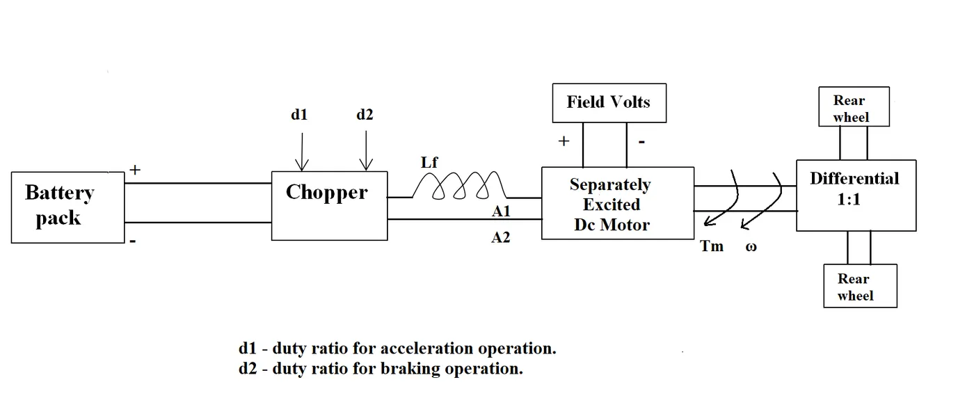
2. An Electric Vehicle's powertrain with 72V battery pack in shown in the diagram below. The duty ratio for acceleration operation is 'd1' and for the braking operation the duty ratio is 'd2'.
 |
The other parameters of the electric vehicle is given below,
Motor and Controller Parameters:
Rated Armature voltage= 72 V
Rated armature current= 400 A
Ra= 0.5Ω, KΦ= 0.7 Volt second
Chopper Switching frequency= 400 Hz
The vehicle speed-torque characteristics are given by the below equation

What is EV steady state speed if duty cycle is 70%?
Soln.
Given Motor parameters:
Battery pack voltage (V) = 72V
Rated Armature voltage= 72 V
Rated armature current= 400 A
Ra= 0.5Ω,
Motor Constant KΦ= 0.7 Volt second
Chopper Switching frequency= 400 Hz
Duty Cycle = 70%ω
The vehicle speed-torque characteristics are given by the below equation
--------------(1)
s the given Duty Cycle is 70%,
the available output voltage to the motor from the DC/Dc converter with input battery pack voltage of 72V is
V= 72*0.70=50.4V
From Speed_Torque Equation of of DC motor ω= (V/kϕ)-(Ra/(kϕ)^2)*T
Rearranging the above equation for Torque, T= (V*kϕ/Ra)-(ω*kϕ^2/Ra) ---------------(2)
Substituting the given values in the above equation,
T=(50.4*0.7/0.5)-(0.7^2/0.5)ω
T=70.56-0.98ω ----------------------(3)
When the vehocle reaches steady state, speed of vehicle Tv=T (Motor Torque)
Equationg (1)&(3)
24.7+ 0.0051*ω^2=70.56-0.98ω
0.0051*ω^2+0.98*ω-45.86=0
Solving above 2nd order Quadratic eqn,
ω={-0.98±√[0.9^2-(4*0.0051*(-45.86))]}/2*0.0051
We get two values for ω,38.915rad/s,-231.072rad/s
Considering the positive value for ω,Steady state speed of vehicle =38.915 rad/s
3. Develop a mathematical model of a DC Motor for the below equation using Simulink.
ω= V/Kϕ -Ra/Kϕ^2 .T
Simulink Model for the given equation:
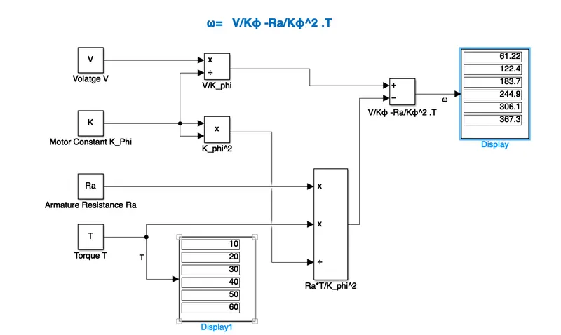
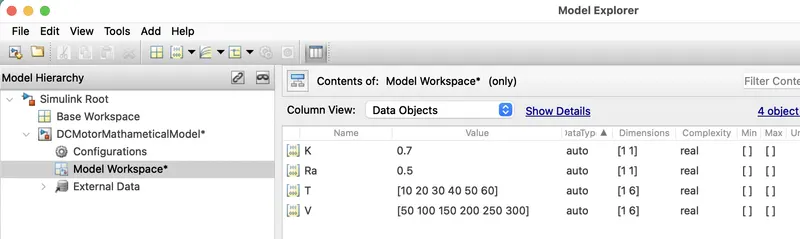
Assigning variable values to model workspace using model explorer
4. Refer to the blog on below topic:
Induction Versus DC brushless motors by Wally Rippel, Tesla
Explain in brief about author’s perspective.
Induction Versus DC brushless motors by Wally Rippel, Tesla
Explain in brief the author’s perspective.
Ans:
- In the blog Induction Vs DC Brushless Motors the author Wally Rippel,Tesla compared the two types of motors
- According to the author DC brushless and induction drives use motors having similar stators. Both drives use 3-phase modulating inverters. The only differences are the rotors and the inverter controls. And with digital controllers, the only control differences are with control code.
- One of the main differences is that much less rotor heat is generated with the DC brushless drive.
- In an ideal brushless drive, the strength of the magnetic field produced by the permanent magnets would be adjustable.
- Induction motor have some advantages like: it has no magnets. The motor has the ability to start under load. No inverter is needed. Some disadvantages of Induction motors are: They cannot operate from DC; AC is a must. Shaft speed is proportionate to line frequency. Hence, when used with utility power, they are constant speed machines. When operated from utility power, they have limited starting torque and somewhat limited running peak torque capabilities, when compared to DC type machines.
- Brushless DC motor have some advantages like: much less rotor heat is generated with the DC brushless drive. The peak point energy efficiency for a DC brushless drive will typically be a few percentage points higher than for an induction drive. Some disadvantages of Brushless DC motor are: as machine size grows, the magnetic losses increase proportionately and part load efficiency drops. Permanent magnets are expensive and difficult to handle due to very large forces that come into play when anything ferromagnetic gets close to them.
- According to the author DC brushless drives will likely continue to dominate in the hybrid and coming plug-in hybrid markets, and induction drives will likely maintain dominance for the high-performance pure electrics. The question is what will happen as hybrids become more electrically intensive and as their performance levels increase? The fact that so much of the hardware is common for both drives could mean that we will see induction and DC brushless life and work side by side during the coming golden era of hybrid and electric vehicles.