Final Project: Design of an Electric Vehicle
Final Project: Design of an Electric Vehicle
Create a MATLAB model of electric car which uses a battery and a DC motor. Choose suitable blocks from Powertrain block set. Prepare a report about your model including following:
Objectives:
1. System level configurations
2. Model parameters
3. Results
4. Conclusion
AIM:
To create a MATLAB model of electric car which uses a battery and a DC motor by choose suitable blocks from Powertrain block set, and to prepare a detailed report of the model.
Introduction to Electric cars:
An electric car is a one powered by an electric motor rather than a traditional petrol/diesel engine. This electric motor is powered by rechargeable batteries that can be charged by common household electricity.
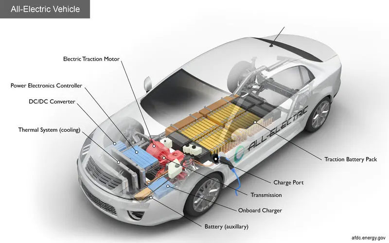
How does an electric car works ?
Advantages of a BEV (Battery Electric vehicle):
- Creates very little noise
- Doesn't burn fossil fuels, instead uses rechargeable batteries
- They produce no tailpipe emissions, so are better for the planet.
- No exhaust, spark plugs, clutch or gears
- Do not need much maintenance as they have fewer moving parts.
- They often have a smoother drive than petrol cars.
Downsides of electric cars:
- They can have a comparatively limited range. This depends on the model, the weather and the style of driving.
- Depending on the car and the charger, they can take a long time to charge.
- Batteries may need replacing after 5-10 years in order to retain efficiency. After a few thousand few charges, the battery will lose its ability to hold charge as effectively.
- Not all parts of the country will have a charging point nearby (might be in future available)
Key Components of a Pure electric car:
Drive cycle input:
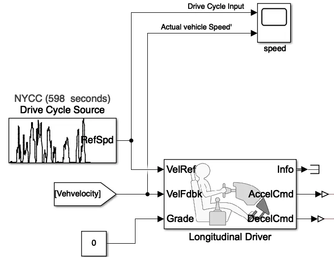
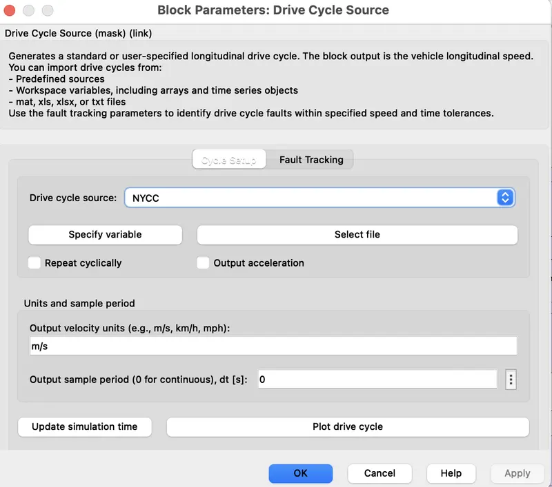
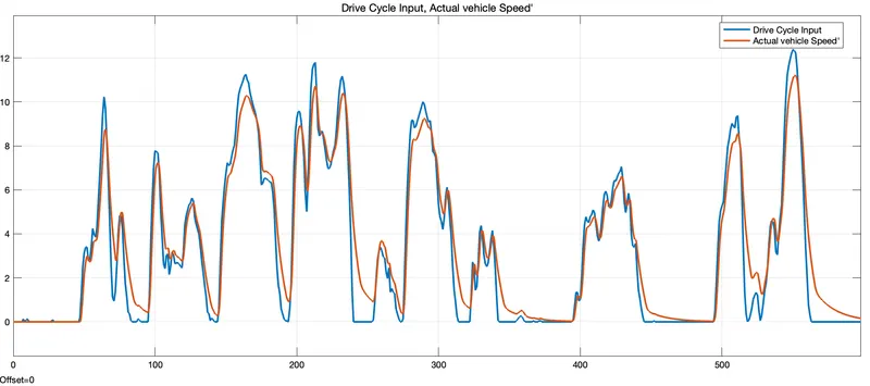
Adrive cycle gives constant velocity computation. It is defined as the variation in speed with respect to time. It is mainly developed for the practical test of emissions. It is more realistic case of better modeling of energy and range of battery. Drive cycle source provide a user specified longitudinal drive cycle. NYCC is selected here as the drive cycle which is one of the standard drive cycles. The simulation stop time is set to 598 second s which is same as drive cycle time.
Longitudinal Driver:
A longitudinal driver is a simulated driving environment where whatever the velocity input is, they will be followed by the vehicle. It act in such a way that the difference between the 2 inputs (actual speed from the car and the reference speed from input drive cycle source) is minimized.
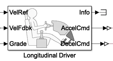
It is clear from the block above that there will be a reference velocity, feedback velocity, a grade option which is grounded or provided zero value ( as here) to terminate it. The other end consists of an acceleration command to drive the car, a deceleration command to give braking command when needed and a info part which is also not required thus terminated using a terminator block.
These are the parameter values for the given block:
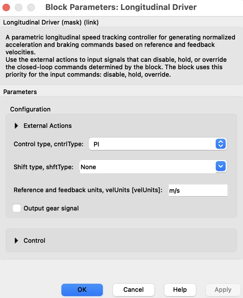
Here Proportional Integral controllers are selected as the controller for minimizing the error. PI controllers are efficient and good in performance.
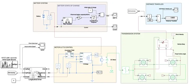
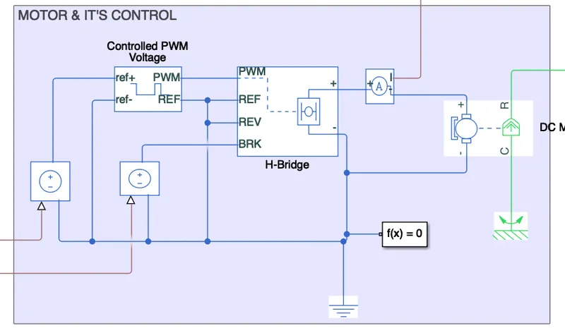
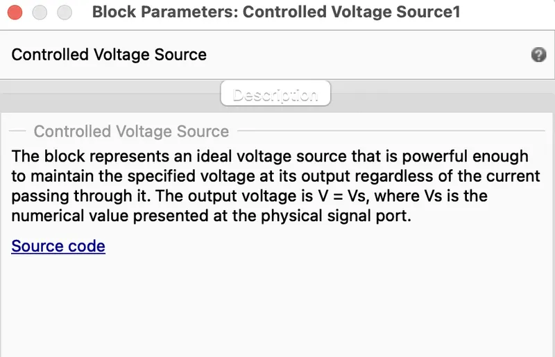
It controls the motor action and is connected in between the vehicle body and longitudinal block and is also connected with the battery. It controls the speed of motor and control the charging and discharging of motor according to the motoring and braking option.
Controlled PWM voltage:
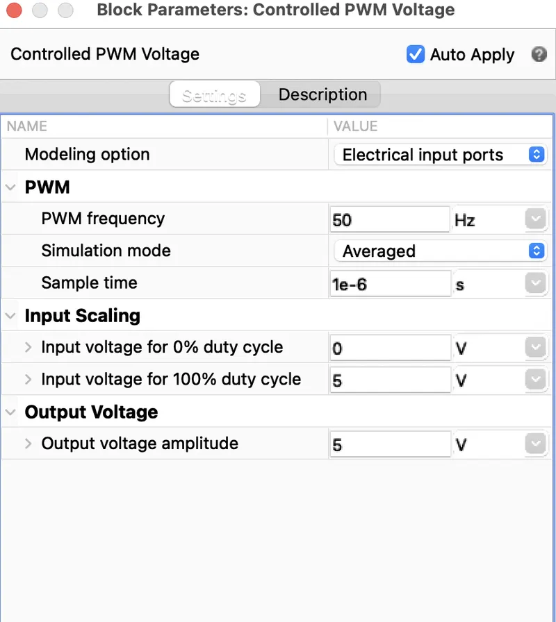
It represents Pulse Width Modulated voltage source. The block has 2 modeling variants for the simulation like PWM and averaged. To reduce simulation run time here it is selected as averaged.The block calculates the duty cycle based on the reference voltage across its positive reference and negetive reference ports. This modeling is default.
H- Bridge:
The H-Bridge block represents an H-bridge motor driver.
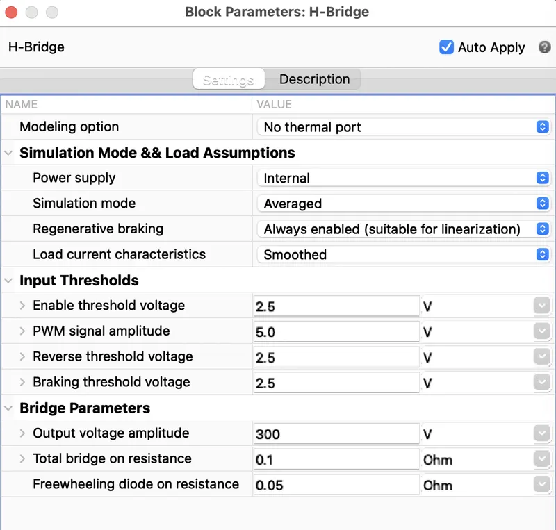
t is usually connected along with the PWM voltage controller block. It is mainly used to drive a particular load. Here the load is dc motor drive. Here also the simulation mode is set as averaged as same as the pwm voltage controller block. This applies the average the average of the demanded PWM voltage to the motor. Braking mode is involved when the voltage presented in the BRK port larger than the braking threshold voltage. PWM and ref ports are connected to respective ports of controlled pwm voltage block. REV is connected to REF port and grounded together. The positive and negetive terminal connected to the dc motor along with a current sensor.
Current sensor:
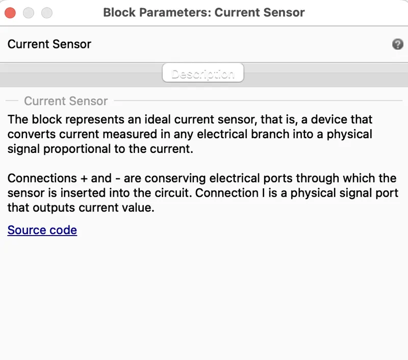
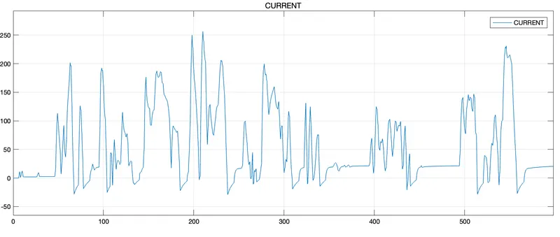
Is Used to sense the current across the connected terminals. It converts the current measured in any electrical branch into a physical signal propotional to the current.
DC Motor :
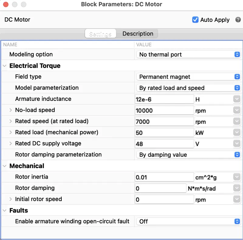
DC Motor block represents the electrical and torque characteristics of the motor. The positive and negetive terminals are connected to the Hbridge and the ground. C and R are the mechanical ports which are connected to the respective mechanical gear. There is a connection port across it to connect it further with the mechanical system. Connection port 4 is given to the shaft.
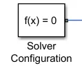
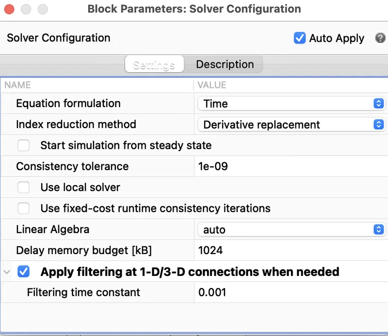
Solver configuration:
Here each physical network represented by a connected simscape block is connected to the solver configuration for the simulation to run properly. It specifies the solver parameters that the model needs before starting the simulation.
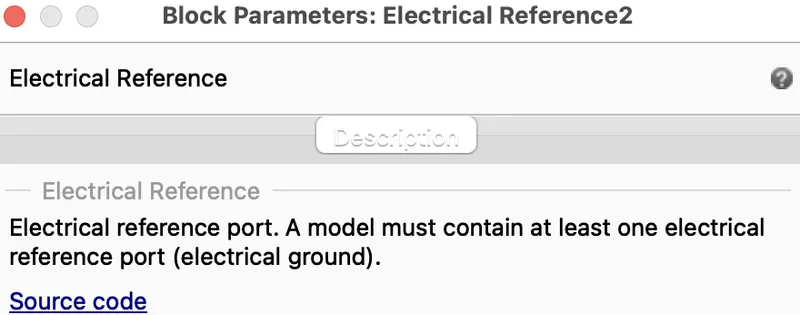
Electrical reference:
Each electrical block is connected to an electrical reference or a negetive ports are grounded together.
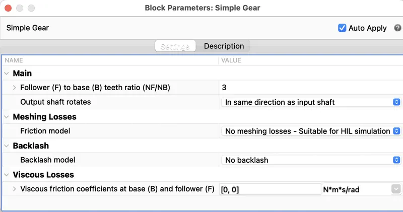
Simple gear:
It represents a gear box that constaints the connected driveline axes of base gear and follower gear to co-rotate with a fixed ratio that we provide. We can choose the follower axis rotation which is either in same direction or in opposite direction. Here we are seleting rotation in same direction.
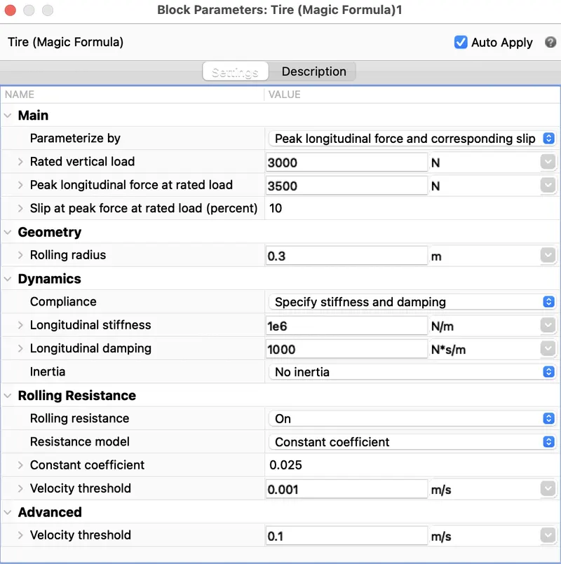
Tire :
It models a tire with longitudinal behaviour. The block can model tire dynamics in constant and variable pavement conditions. It models the tire as a rigid wheel tire combination in contact with the road and subject to slip.
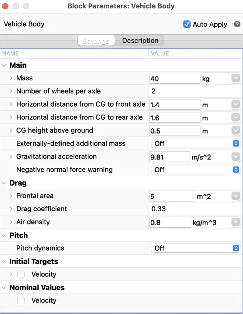
Vehicle body:
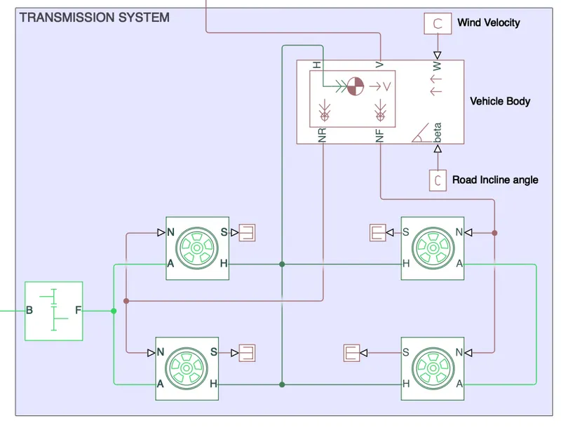
It represents 2 axle vehicle body in longitudinal motion. It can have same or different number of wheels or tires on each axle. Here there is 2 wheels on each axle. The block accounts for body mass, aerodynamic drag, road inclination, road profile etc.Vehicle body is used as a control mechanism.
PS Constant bock:
This block generates physical signal of a constant value. Here there is 2 PS constant blocks used connected across W and Beta ports of veicle body.
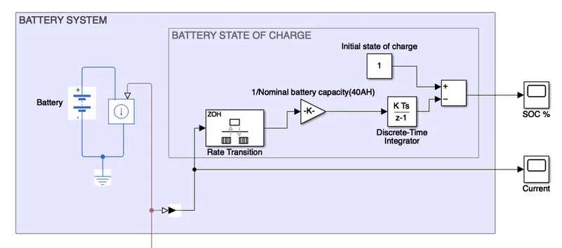
4) Battery subsystem:
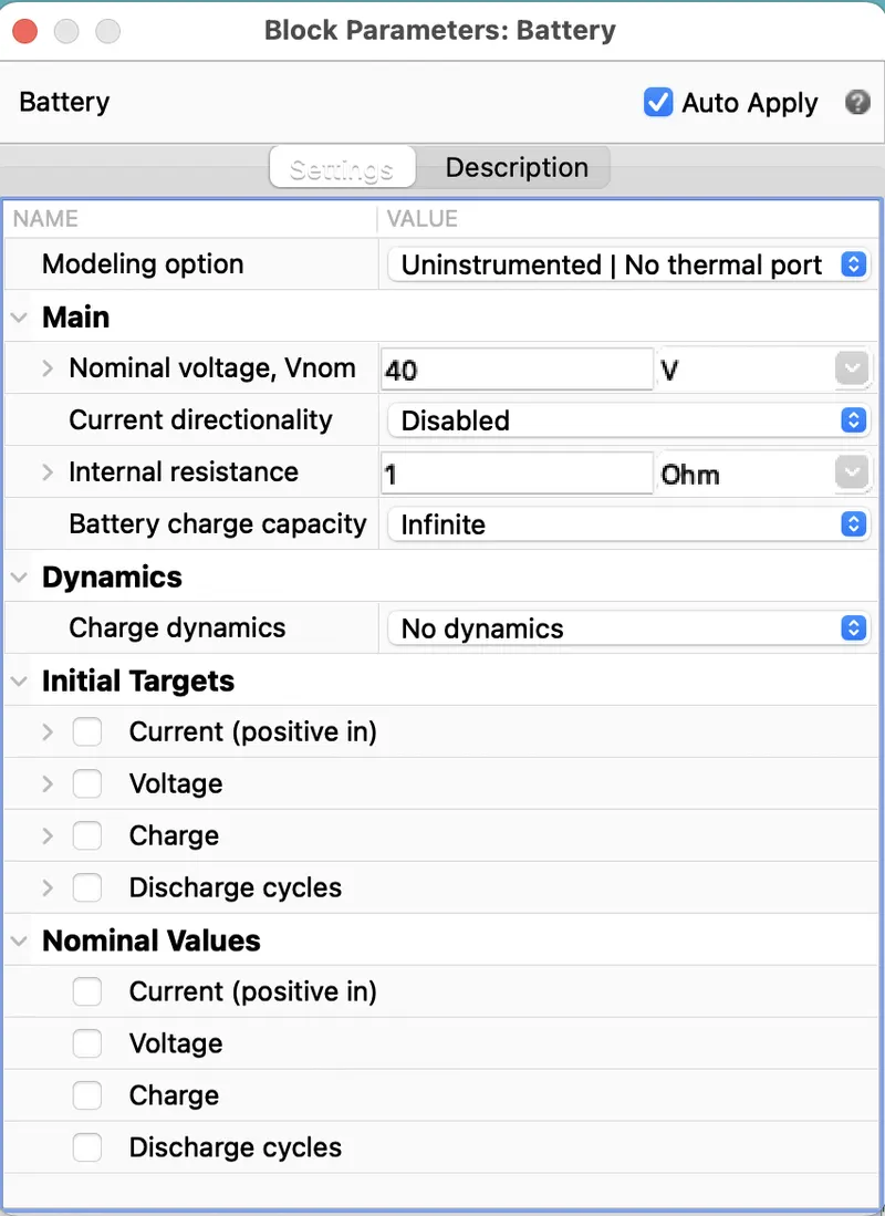
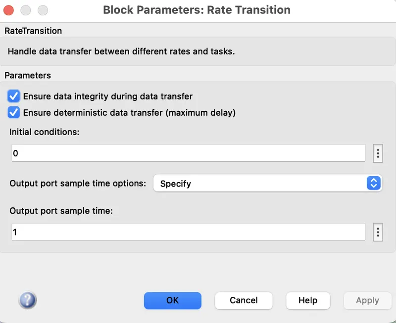
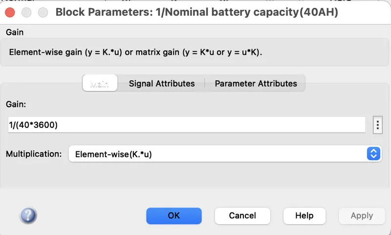
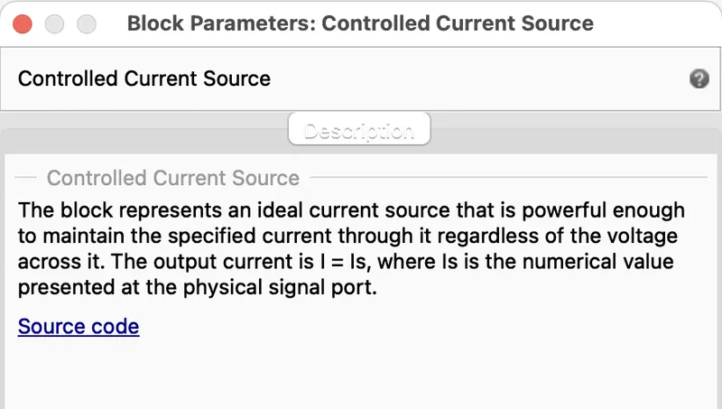
It consists of battery, controlled current source, rate transition block, gain block, discrete time integrator, add block, constant block, connection port.
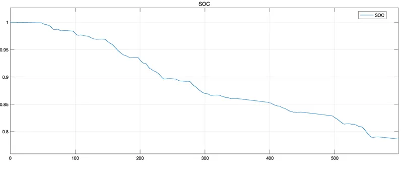
Here we need a battery model SOC or state of charge with respect to the voltage and charging and discharging current. With this battery model we can update the depth of discharge of battery to know its draining.
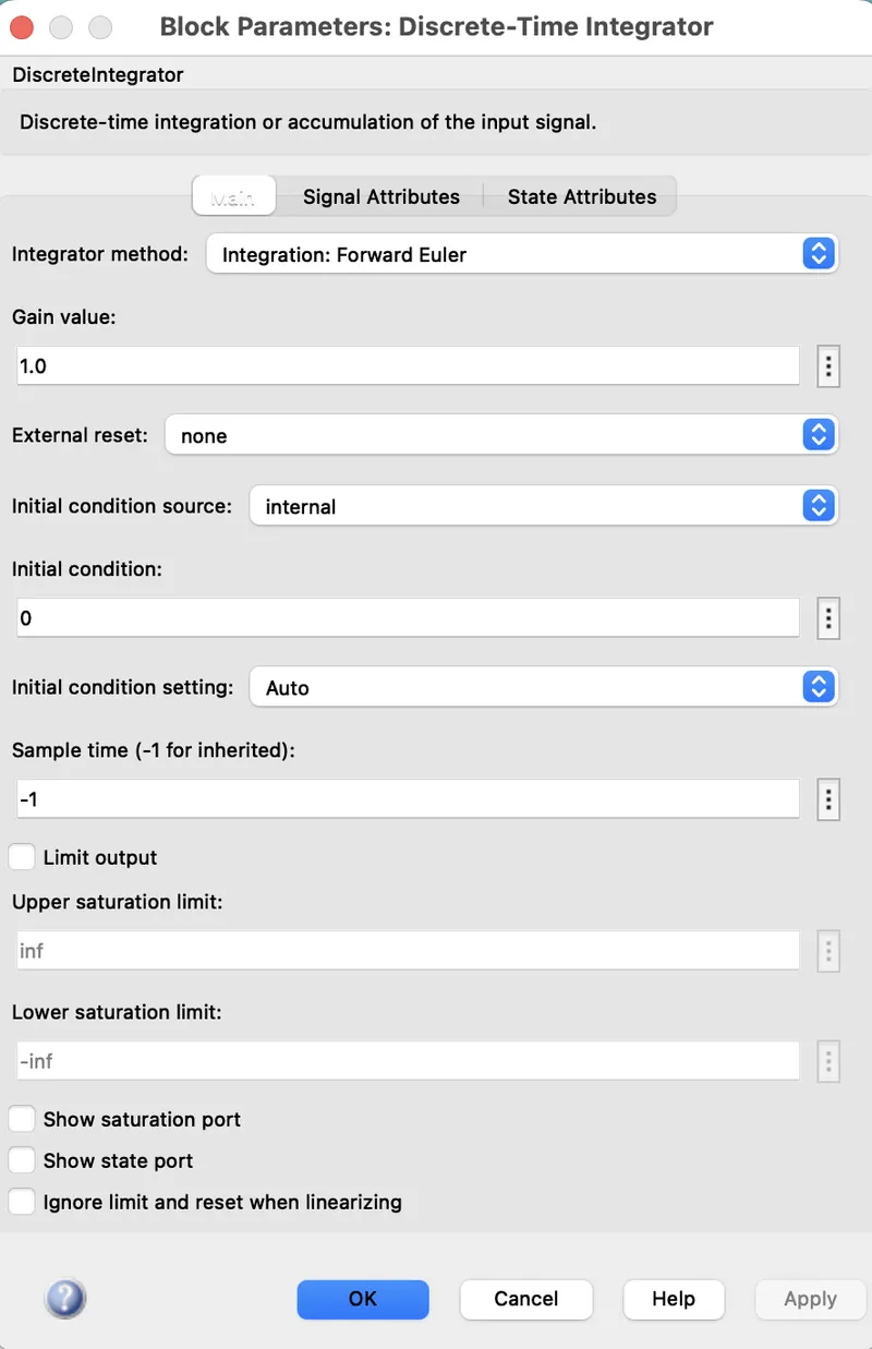
Discrete time integrator:
It is used in place of a integrator block to create a purely discrete model. We can define initial conditions, input gain value, upper and lower limits on the integral.
Conclusion: