Project-1: Powertrain for aircraft in runways
Project-1: Powertrain for aircraft in runways
Part A:
1. Search and list out the total weight of various types of aircrafts.
What is an Aircraft?
An aircraft is a vehicle or machine that is able to fly by gaining support from the air. It counters the force of gravity by using either static lift or by using the dynamic lift of an airfoil, or in a few cases the downward thrust from jet engines.
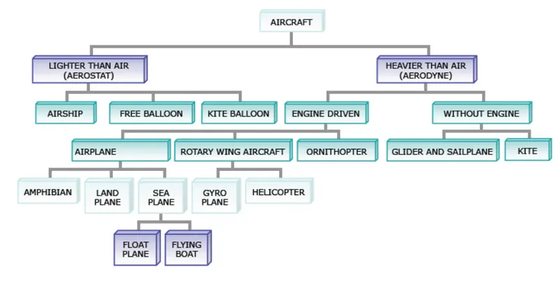
Aircrafts are classified as follows:
Weight is one of the major concerns in designing an aircraft. An Aircraft toral weight includes
i) Aircraft's Empty Eeight (AEW) - sometimes referred to as Operator's Empty Weight (OEW)
ii) Weight of the fuel -
iii) Weight of the crew, passengers and cargo & baggage.
Aircraft's Maximum Gross Takeoff Weights (MGTW): This is the maximum permissible weight the aircraft can weigh as it lifts off the ground at takeoff. This includes the aircraft’s empty weight, the fuel, the crew, the passengers, and all the cargo.
| Manufacturer's Perspective | Operator's perspective |
|
|
Operator Weight Build-Up
Figure below illustrates the composition of weight categories that are reflected in most commercial
aircraft. Starting from the Manufacturer’s Empty Weight (MEW) and adding elements to make the aircraft
operational. From the chart below we can gain a mathematical perspective on how to calculate a number
of weight categories, which are summarized below:
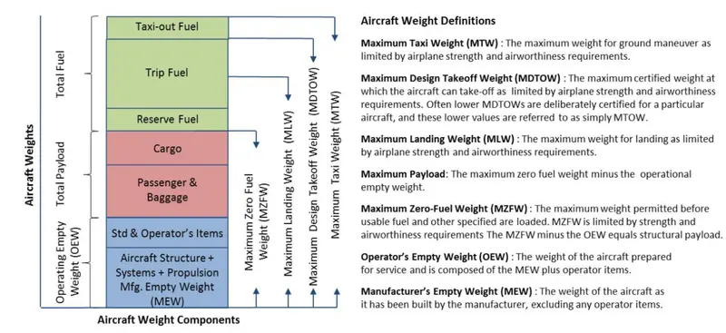
OEW = MEW + SI + OI
Max Payload = MZFW – OEW
MTOW = MZFW + Reserve Fuel + Trip Fuel
MTW = MTOW + Taxi-out Fuel
Typical Airplane Weights
Below is a table of some of the most common aircraft flying around our skies today:
| Aircraft | Empty Weight | Max Fuel Weight | Max Cargo Weight | Max Gross Takeoff Weight |
|---|---|---|---|---|
| Antanov AN-225 | 285,000 kg | 300,000 kg | 190,000 kg | 640,000 kg |
| Airbus A380-800 | 277,000 kg | 254,000 kg | 84,000 kg | 575,000 kg |
| Boeing 747-800 | 220,100 kg | 194,000 kg | 134,000 kg | 447,700 kg |
| Airbus A340-500 | 68,000 kg | 175,000 kg | 54,000 kg | 372,000 kg |
| Boeing 777-300ER | 168,000 kg | 145,500 kg | 67,100 kg | 352,000 kg |
| Boeing 787-10 | 135,500 kg | 101,500 kg | 57,300 kg | 254,000 kg |
| Boeing 737-900 | 44,700 kg | 24,000 kg | 20,200 kg | 85,000 kg |
| Airbus A320-100 | 42,600 kg | 22,100 kg | 20,000 kg | 68,000 kg |
| Embraer 190 | 28,800 kg | 13,000 kg | 13,100 kg | 48,000 kg |
| Gulfstream G650 | 24,500 kg | 21,900 kg | 3,000 kg | 45,200 kg |
| Bombardier CRJ900 | 21,850 kg | 8,900 kg | 2,760 kg | 36,500 kg |
| Bombardier Q400 | 17,800 kg | 5,300 kg | 8,500 kg | 28,000 kg |
| Learjet 75 | 6,300 kg | 2,750 kg | 1,300 kg | 9,700 kg |
| Cessna Citation CJ4 | 4,700 kg | 2,650 kg | 1,000 kg | 7,800 kg |
| Beechcraft King Air B100 | 3,200 kg | 1,450 kg | 1,900 kg | 5,400 kg |
| Diamond DA50 RG | 1,450 kg | 155 lbs | 560 kg | 2,000 kg |
| Cessna 206H | 990 kg | 235 kg | 520 kg | 1,630 kg |
| Sirrus SR22 | 1,000 kg | 220 kg | 430 kg | 1,630 kg |
| Cessna 172R | 770 kg | 170 kg | 255 kg | 1,100 kg |
2. Is there any difference between ground speed and air speed?
Ans.
Ground speed:
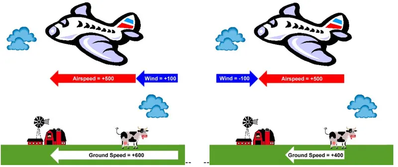
Ground speed is the actual speed that an aircraft travels over the ground and is also referred to as "shadow speed." Ground speed combines the aircraft’s airspeed and the wind speed relative to the aircraft’s direction of flight. An aircraft’s airspeed is determined not by how much distance it covers in a set time, but by a combination of its forward speed and the speed of the wind that is blowing towards the aircraft.
Air speed:
Airspeed is the speed of an aircraft relative to the air. This speed is measured inside the aircraft with an airspeed indicator, which is a device that can compute how fast the airplane is traveling. This device uses the ram-air pressure from instruments outside the aircraft and compares it to the non-moving air inside the vehicle.
Ground speed and airspeed are not always the same speed. On a windy day, an airplane may have an airspeed of 80 knots but a ground speed of only 60 knots. The term "shadow speed" comes from the speed of the airplane’s shadow on the ground. If an aircraft has an airspeed of 80 knots but a ground speed of 60 knots, a car that follows the shadow will only need to go 60 knots to keep the same speed as the airplane.
Most people have heard of headwinds and tailwinds. A tailwind will help push an aircraft faster so that it reaches its destination more quickly, while a headwind pushes against the aircraft and slows it down. A headwind will detract from an aircraft’s ground speed, while a tailwind will increase it.
Effect of Wind on the aircraftflight path:
Let us imagine that we want to fly from A to B along the path (desired course) shown in Figure 1, and the wind is blowing across the path from the left. The wind will try to blow us off our desired course. And if we do not compensate for this effect, we will fly along the path shown in yellow (track) and end up at point C.
Therefore, a navigator/pilot needs to counteract the effect of wind to maintain the desired course.
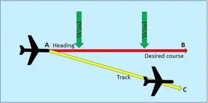
Fig.1
Wind Correction Angle:
The wind correction angle (or WCA) is the correction angle applied to the aircraft's course by pointing its nose towards the wind in such a way that it counteracts the effect of wind. This will ensure that our aircraft follows its desired course.To understand this, let us consider Figure 2.
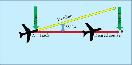
Fig.2
Due to the effect of the wind, the aircraft will tend to drift to the right (as shown in Figure 1). Therefore, we must point the nose of the aircraft to the left to correct this drift. The angle between the heading (i.e., the direction in which the nose of the aircraft points) and the desired course is called wind correction angle.
Reference link : Effect of Wind & wind-correction-angle
3. Why is it not recommended to use aircraft engine power to move it on the ground at Airport?
Ans.
Aircraft engines are not recommended to use on the ground at airport due to its high power engines which may cause safety related issues and due to some other reasons, we will discuss them in following section
1. AIRCRAFT ENGINES CAN CREAT HAZARDOUS CONDITIONS:
When an aircraft's engine is activated, the thrust can create a high-speed wind that can easily cause damage to the airport terminal, surrounding ground vehicles, jetway, baggage and most importantly, ground personnel. Aircraft towing equipment is typically used for the towing and pushback process to avoid some of the significant hazards posed by aircraft engines.
Suppressing the use of engines is especially important when towing a large aircraft, as their more powerful thrust capabilities can become exceedingly dangerous.
Engine thrust can easily send any loose items airborne, turn the tiniest grains of dust into hazardous projectiles and create debris that can cause damage to multi-million dollar engines. Additionally, aircraft engines consume a great deal of fuel and generate extreme noise that can be harmful to ground personnel.
2. FOR MAINTENANCE PURPOSE OF AIRCRAFTS :
It's also not cost-efficient to start aircraft engines just to reposition an aircraft for maintenance purposes.
Instead of using aircrafts engine, towing and pushback tugs for aircraft are also used to make general maintenance easier for ground personnel.
When an aircraft needs to be moved to a hangar for maintenance purposes or is not required for flight, the easiest way is to send an aircraft tug to the tow-in gate for transport. Aircraft towing frees up time for the airline, maintenance team, airport ground controllers and pilots who don't need to waste time getting the engines started.
Typically, ground personnel are trained to only need the aircraft brake system when towing a large aircraft. Using a pushback tug for aircraft is simply a more economical and safer option than running the engines.
3.PILOTS HAVE LIMITED VISIBILITY FROM THE FLIGHT DECK :
Pilots do not have a clear view of the rear from the flight deck and thus rely on aircraft towing equipment for ground pushback when needed. Once the aircraft is perfectly positioned and far from the terminal tow-in gate and other vehicles, the airport tug is disconnected and the aircraft can use its engines and steering to move to the runway for takeoff.
4.TERMINAL TOW-IN GATES ARE CONFINED SPACES :
Aircraft towing from the taxiway occurs with significant time constraints, so pilots and ground personnel are under extreme pressure to navigate the aircraft quickly and efficiently. The tight confines of the terminal tow-in gate combined with the restricted view of the pilots generally always require a tow in order to arrive safely and on time.
Even though pilots follow taxi centerlines, aircraft with very large wingspans are often faced with the challenge of having adequate clearance. If an airplane connects with another aircraft or hits a gate terminal, it can cause significant damage, huge expenses and contribute to lost time for extra maintenance repairs.
Aircraft towing can prevent contact with other structures because ground personnel have much better visibility from the airplane tug. With the aid of ground personnel walking with the wings and tail, the airport tug driver can precisely position the aircraft to ensure it will not hit a structure, vehicle, person or another aircraft. In addition to this, the airplane tug driver is in constant communication with the pilots to ensure the aircraft will brake if an emergency occurs.
5.FOR GOING IN REVERSE :
Typically, most aircraft cannot move in reverse without the help of aircraft towing equipment. Planes are not designed with a reverse option that pilots can use for backward movement, so pushback tugs for aircraft are the only option when moving aircraft into hangars or away from the terminal building.
This is because aircraft are not outfitted with gears or transmission for propulsion – power for movement is derived solely from the engines through thrust. When aircraft tugs are used to tow planes, an airline can maximize safety and optimize efficiency with on-ground operations.
While most commercial airliners with jet engines have thrust-reversing capabilities, they can only be used as additional braking power during landing. In addition to the problems mentioned above associated with using aircraft engines, reverse thrust also has what is known as the lowest-speed-of-operation limit. If reverse thrust is used below the speed of 80kts, it's very likely the engines will become heavily damaged.
4. How an aircraft is pushed to runway when its ready to take off?
Ans.
Usually aircraft are at parking or at terminal departure gates, when an aircraft is ready to take off from its position, we need to push the aircraft back to runway.
Eventhough aircraft engines might capable of pushing back themselves in reverse direction, their engines' heavy thrust and extreme noise , easily cause damage to the airport terminal, surrounding ground vehicles, jetway, baggage and most importantly, ground personnel. and also its not cost-effective to use aircraft engine to move the aircraft on ground.
Inorder to do this, we are using aircraft towing equipment called tugs or tractors
Towbars are connected to the axle of an aircraft's nose landing gear and the front or rear of the aircraft tug. Once connected, the driver can easily maneuver and tow planes from the tow-in gate out to the taxiway. The raised cabin of the airplane tug allows the driver to have a full 360-degree view to prevent any collisions or near misses – something especially vital when towing large aircraft.
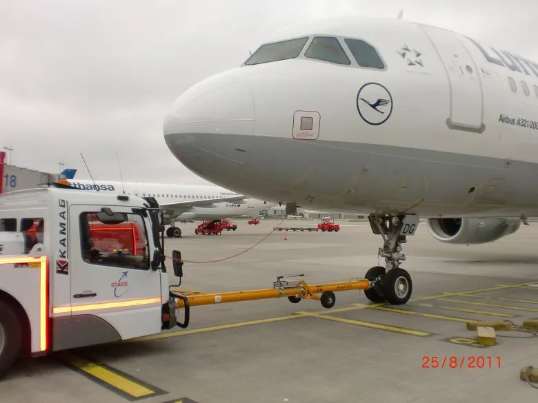
Fig. Using a towbar for towing an aircraft
Another type of aircraft towing equipment that has become more popular around large airports is towbarless tugs. These airport tugs are purposely designed for towing aircraft without the need for additional equipment like a towbar. Towbarless tugs come in a wide range of sizes to suit the needs of both heavy and light aircraft alike.
Towbarless tugs work by reversing the tug up to the aircraft nose landing gear. The plane's front tires are then placed against a stop while a locking arm closes around the other side of the tires. Once it's secure, the airport tug will lift the landing gear tires off the ground. Then, the towbarless tug can easily move the aircraft around once the pilot has released the brakes.
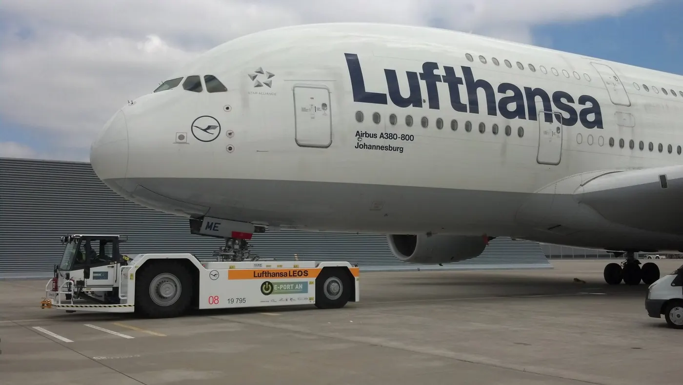
Fig. Towbarless tugs for aircraft towing
5. Learn about take off power, tyre design, rolling resistance, tyre pressure, brake forces when landing.
Ans.
Takeoff is the phase of flight in which an aerospace vehicle leaves the ground and becomes airborne. For aircraft traveling vertically, this is known as liftoff. For aircraft that take off horizontally, this usually involves starting with a transition from moving along the ground on a runway.
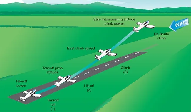
Take Off Power :
This is the amount of power that an air craft's engine is allowed to produce for a limited period of time for takeoff. The use of takeoff power is usually limited to 5 min for reciprocating engines and up to 2½ min for gas turbine engines. This may not always be the case. Specifically, with respect to reciprocating engines, it is the brake horsepower developed under standard, sea- level conditions and under the maximum conditions of the crankshaft rotational speed and the engine manifold pressure approved for the normal take-off.
It is limited in continuous use to the period of time shown in the approved engine specifications. With respect to gas turbine -engines, it is the thrust developed under static conditions at a specified altitude and atmospheric conditions of the rotor shaft rotational speed and gas temperature approved for the normal takeoff. It is limited in continuous use to the period of time shown in the approved engine specification
Large transport category aircraft may use a reduced power for take-off, where less than full power is applied in order to prolong engine life, reduce maintanance costs and reduce noise emissions.Also in some (emergency) cases the power can be increased for better performance.
Tyre design :
An aircraft tire must withstand a wide range of operational conditions. While on the ground, it must support the weight of the aircraft. During taxi, it must provide a stable, cushioned ride while resisting heat generation, abrasion, and wear. During take-off, the tire structure must be able to endure not only the aircraft load, but also the forces generated at high angular velocities. Landing requires the tire to absorb impact shocks while also it also provide the necessary traction for braking and stopping of an aeroplane. All of this must be accomplished while providing a long and reliable service life
Ply Rating – Ply Rating is used to identify the maximum recommended load rating and inflation pressure for a specified tyre. It is an index of tyre strength.
Speed Rating – The speed rating is the maximum takeoff speed to which the tyre has been tested.
Skid Depth – Skid depth is the distance between the tread surface and the deepest groove as measured in the mould.
Tyre Construction:
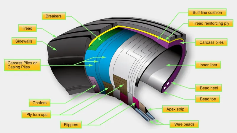
A tire follows a layered construction approach where each layer (region) of the tire serves a different purpose. Broadly speaking, a tire can be divided into four specific regions: the bead, ply, tread and sidewall.
Refer to the image below which shows the make-up of a typical aviation tire.
BEAD
The bead consists of bundles of high strength steel wire encased in rubber. This provides the tire with lateral strength, anchoring the structural plies and transferring the impact loads generated in the tire onto the wheel rim. Tires that are designed to operate at higher speeds and at higher loads may have multiple bundles of beading to effectively transfer the loads and resist the large tire deformations that result.
PLY REGION
A tire is built from multiple plies which are laid on top of each-other to give the tire its structure and form. Plies are usually manufactured from nylon fabric sandwiched between layers of rubber. These structural members are sometimes called carcass plies as they form the skeleton of the tire. The concept of ply rating refers to the relative strength of the tire’s ply layup. The ends of each ply are anchored to the beading on each side of the tire to transfer load out the tire and into the wheel.
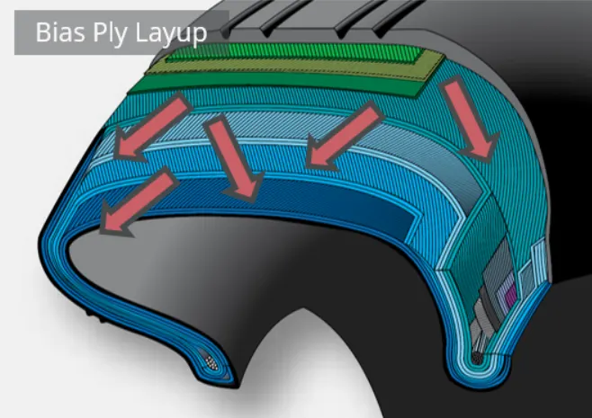
Plies are characterised according to their orientation relative to the direction of motion of the tire. Traditionally, plies were orientated predominantly in the direction of motion of the tire (with a bias of between 30° and 60°). This is called a bias ply layup as the plies are orientated with a bias to the direction of rotation. Bias plies result in a tire that is flexible and able to absorb the loads typically seen during landing and take-off.
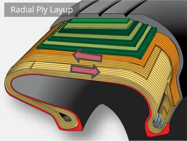
A radial ply layup is one where the plies are laid perpendicular to the direction of motion of the tire. This results in a stronger tire, but one that is not able to deflect and flex as much as in a bias ply layup.
TREAD
The tread refers to the wearable part of the tire that is designed to come into contract with the ground. The tread is located on the tire crown and must resist frictional wear, abrasion, cracking and cuts that occur as a result of the landing surface and condition of the runway.
The tread pattern seen on the tire differs according to the operational requirements of the tire. Most tires are grooved in the circumferential direction which provides good operating characteristics for aircraft generally flown into and out of prepared runways. The grooves that characterize a rib tread tire assist in cooling the tire and provide a means for water to channel away from the tire in wet conditions.
Aircraft operating from unprepared or unpaved surfaces may be fitted with a cross-tread pattern. This diamond pattern is cut deep into the tire and provides more traction that the rib tread design in soft ground. On a hard surface (asphalt runway) the tire has a smaller total contact area and so will provide less traction that a tire with a rib tread.
Some older aircraft may have a smooth tread with no ribs or cut-outs. This provides the greatest traction, largest contact area, and subsequently the greatest frictional force which assists in stopping the aircraft.
SIDEWALL
The sidewall of a tire is designed to protect the plies (carcass) that gives the tire its strength. Information about the tire: its dimensions, speed rating, ply rating, direction of rotation, manufacturer etc is printed on to the sidewall for easy reference. The inner sidewall is covered by an inner liner which is a thin rubber liner designed to prevent damage to the carcass plies. Small vent holes in the sidewall are built-in to allow trapped air in the plies to escape. This helps prevent delaminations between plies from forming as a result of the trapped air expanding due to altitude and temperature changes.
Rolling Resistance:
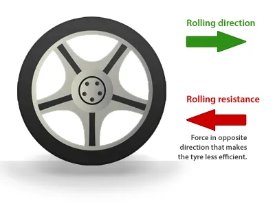
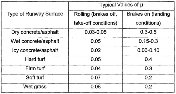
When a tire rolls on the road, mechanical energy is converted to heat as a result of phenomenon referred to as rolling resistance. The term rolling resistance is often mistaken as a measure of the force opposing tire rotation, when instead is actually a measure of rolling energy loss. in another terms we can say rolling resistance is the effort required to keep a given tire rolling. Its magnitude depends on the tire used, roughness of road, inflation pressure, load and speed. Generally rolling resistance is given by following formula –
Frr=μrr*m*g ---(1)
Rolling Resistance Coefficient:
The coefficient of rolling friction is the indication of how great the rolling resistance is for a given normal force between the wheel and the surface upon which it is rolling.
Rearranging the equation(1), we can get the equation for the coefficient of rolling friction,
μr = Frr/m*g
μrr=coeficient of rolling resistance
where,
- μr is the coefficient of rolling friction for the two surfaces ( its value depends on tire material,tire structure,tire temparature, tire inflation pressure,thread geometry, road roughness, road material, and presence or absence of liquids on road , load, speed)
- Frr is the resistive force of rolling friction
-
m=mass on the tire
-
g=gravitational constant
Tyre pressure:
Aircraft tires are usually inflated with nitrogen to minimize expansion and contraction from extreme changes in ambient temperature and pressure experienced during flight.
- Different aircraft have different tire pressure but normally aircraft tire pressure 200 psi above.
- Depends on the weight of the plane and number of tires it has, but generally the cold pressure is between 200 and 300+ psi.
- They are rubber, like a car tire but specially formulated to stay flexible at -60 Deg F at altitude. They are still very cold after descent to touchdown.
- They are almost all radial tires but without steel belts. Kevlar is used as they do not have to withstand the road hazards a car tire does.
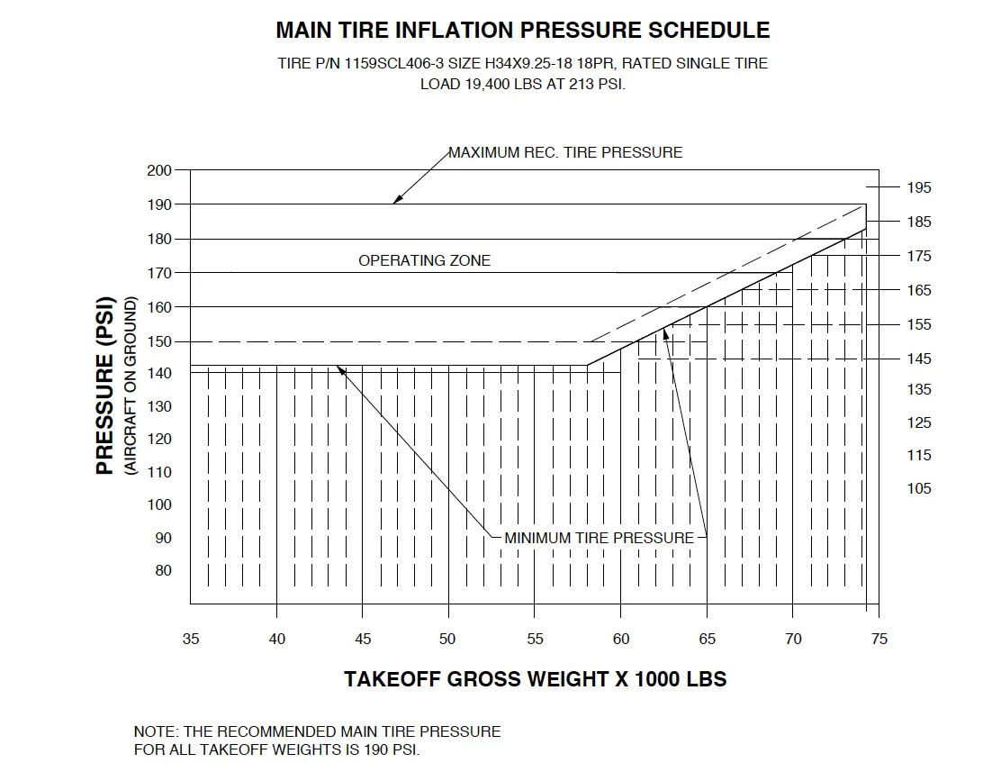
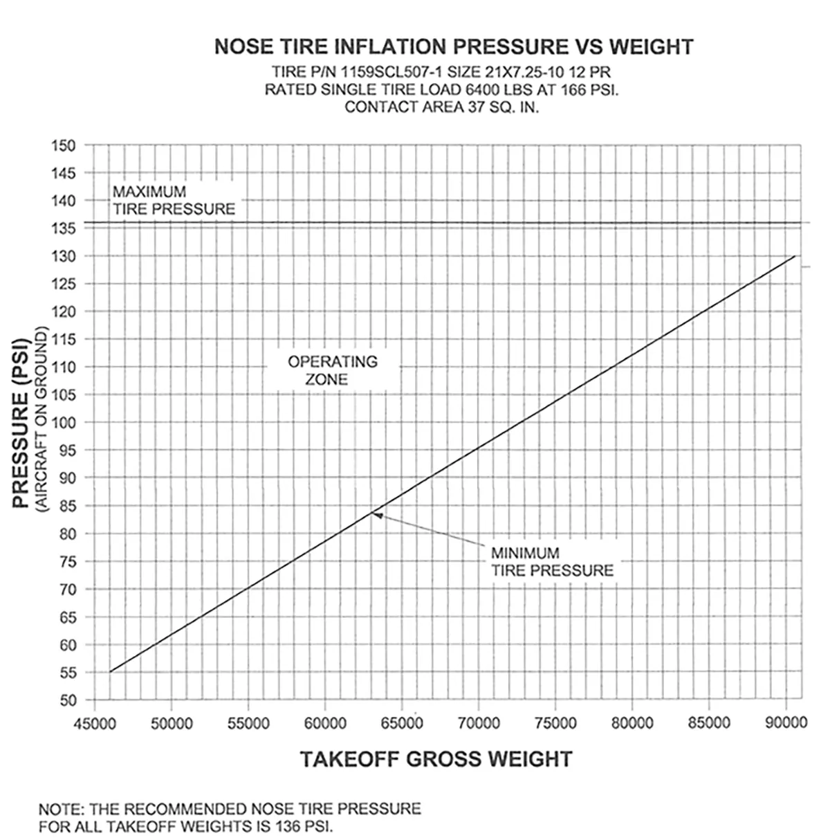
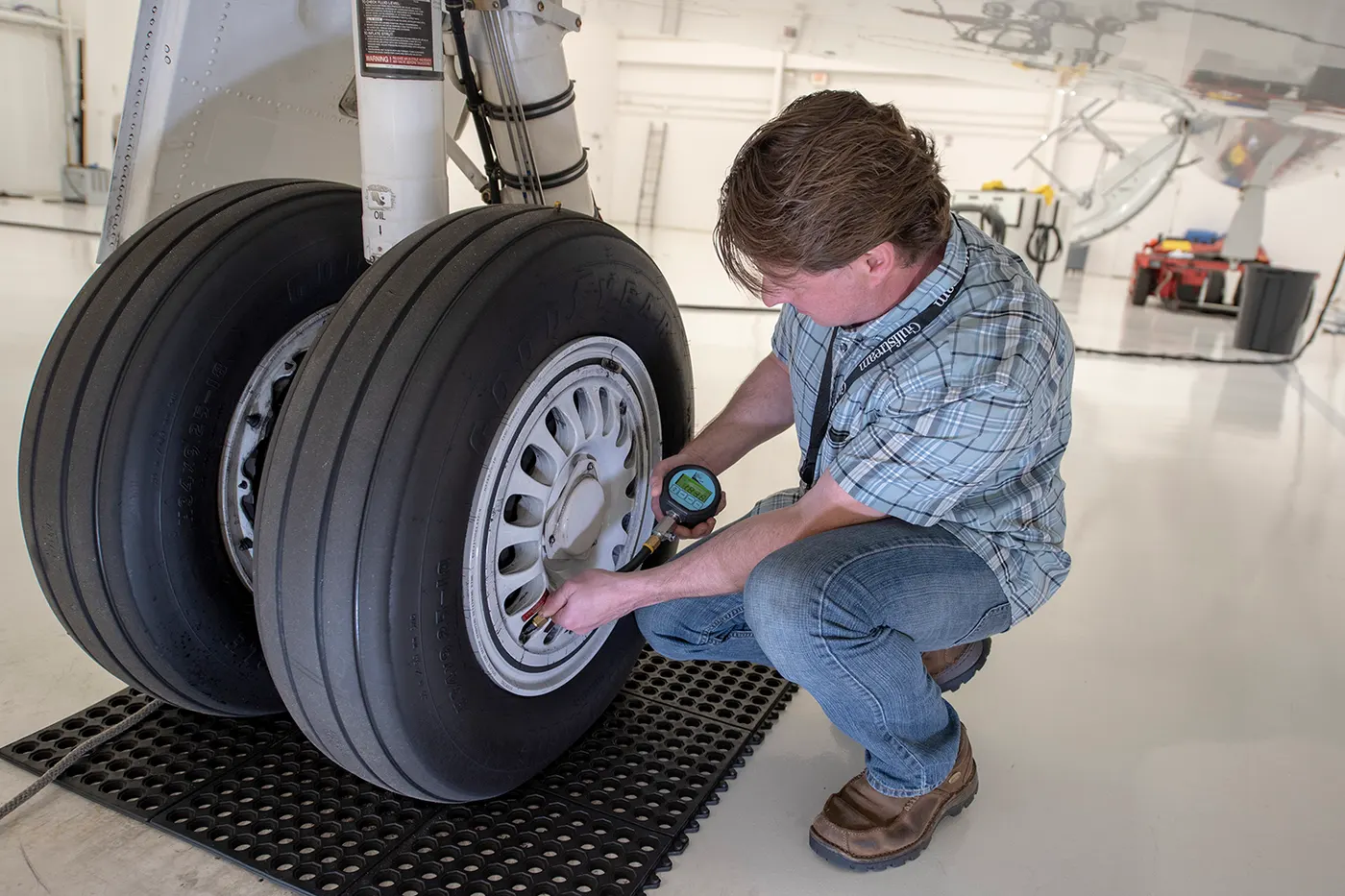
Aircraft tires operate at such high extremes of pressure, load, and speed, their care and service are critically important. The most important action an operator can take to prevent tire-related events is to maintain proper tire inflation pressure. Failure to keep aircraft tires properly inflated can lead to very serious consequences. The most serious of these is the structural failure of the tire. If the tire operates under-inflated or over deflected/overloaded, the nylon cords which form the structure of the tire go in and out of compression as the tire rotates. This weakens the cords – much like a paperclip which is bent back and forth – until eventually, the cords break. If enough cords break, the entire structure will eventually fail.
Another serious consequence of under-inflation is the thrown tread. Overdeflection increases shear between components in the tire as it rolls in and out of contact and deforms. This results in a more rapid build‐up of heat within the tire than would be evident if the tire were properly inflated. At some point, the excessive heat will cause the rubber to revert, or reverse cure. This reverted rubber is like grease with no strength or adhesion to contain the structure. This can allow the tire to decompose, throwing the entire tread or pieces of it. In addition to destroying the tire, thrown treads often result in expensive aircraft damage.
Brake forces when landing:
On any given modern aircraft, there are mainly three types of braking sources; ground spoilers, disc brakes, and thrust reversers. The three combined can provide the most potent braking effect post-landing. Although spoilers and wheel brakes are an integral part of any aircraft, thrust reversers are usually more common in airliners.
Ground Spoilers:
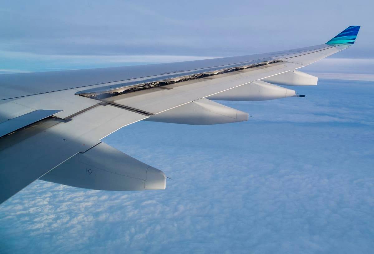
One of the most effective and logical ways of bringing an aircraft to rest is by first cutting off its supply of lift—spoilers on the top of a wing act as a hindrance to the streamlined flow of air. However, spoilers can have varied applications. They can be used to some extent to lower aircraft speeds at the time of descent and approach. This stage is called 'partial deployment' of spoilers.
After touching down, the spoilers take a fully vertical shape by standing straight and out of the wings. In many cases, an additional ground spoiler, which is closer to the fuselage, is used as well. However, there is only a bit that the spoilers can do. The main application of an aircraft spoiler is to cut the lift and provide some sort of a drag. The rest is done by disc brakes and reverse thrusters.
Disc Brakes:
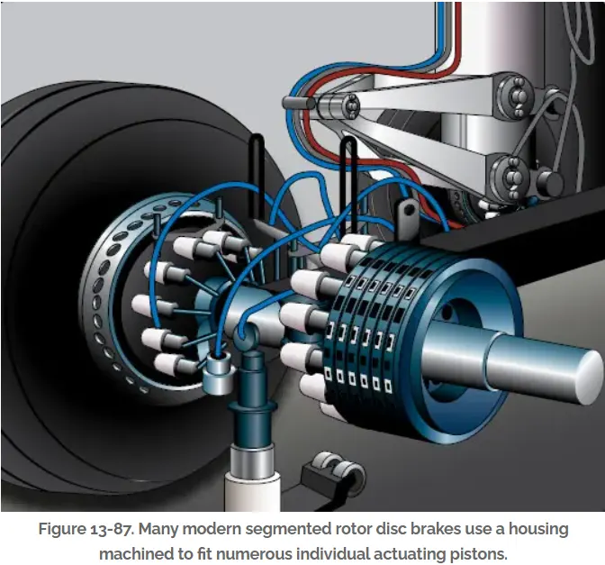
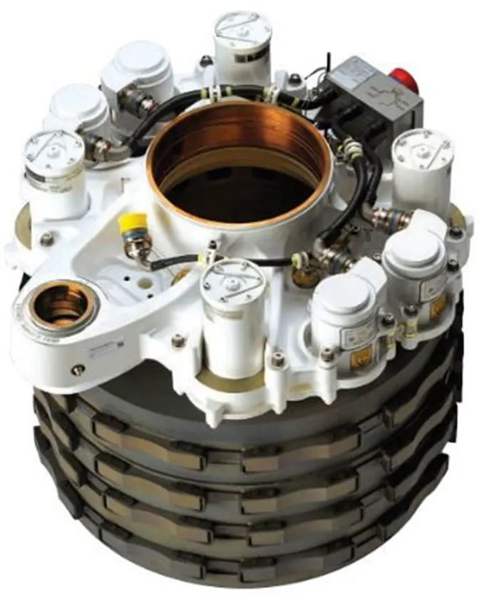
In addition to wing spoilers, airplanes use disc brakes. Airplane disc brakes are similar to the braking system in automobiles. They consist of a pair of calipers that, when engaged, squeeze pads against the rotors of an airplane’s landing gear.
Disc brakes are designed to remain static at all times. In other words, they don’t rotate with the wheels of an airplane’s landing gear. As the wheels turn, the disc brakes will remain static and stationary. They are a vital component of an airplane’s braking system because they are designed to apply pressure to the airplane’s wheels. Disc brakes will squeeze the wheels, thereby slowing down the speed at which they spin. In turn, this reduces the speed of the airplane so that it can come to a complete stop on the runway.
Most-modern aircraft are nowadays equipped with autobraking systems controlled by the autopilot. Depending on the various aspects of landing, the level of the auto brake can be changed to get the desired effect. A lot depends on the length and the state of the runway.
Runway length is an essential factor too. Airports like kai Tak, which had a really tough approach and a high possibility of crosswinds, required an aircraft to apply strong brakes to stop on its short runway. For this reason, most pilots nowadays have to prepare the autobraking system before landing. After the aircraft has slowed down to an extent, the pilots switch to manual braking.
Reverse thrust:
Thrust reversers are a very common part of modern aircraft engines. The application of thrust reversers is more important in heavier aircraft. Some smaller aircraft like the BAE 146 still don't find any use of thrust reversers. This might have to do with a combination of a strong braking system and effective spoilers. However, on a heavy passenger aircraft like an A330, thrust reversers are very crucial.
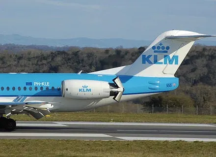
Instead of being pushed towards the back, the reversers pave a sideward opening to allow for the air to push forward. This creates an 'opposite thrust', and this helps the aircraft in stopping. Unlike the process of wheel braking, thrust reversers are mostly manual and applied after the aircraft has safely touched down.
Part B:
6. A). With necessary assumptions, calculate the force and power required to push / pull an aircraft by a towing vehicle.
Ans.
The Towing vehicle should account for the following to produce enough thrust force to move itslef and to tow the aircraft:
- Rolling resistance force of aircraft
- Inertial force of aircraft
- Drag force aircraft experiences
- Rolling resistance force of Towing vehicle
- Inertial force of Towing vehicle
- Drag force Towing vehicle experiences
Boeing 737-400:
| Max ramp weight-m | 68,000kg |
| Wingspan area -A | 105.4 |
| Assumptions | |
| Coefficient of rolling resistance-μrr | 0.02 |
| Air density -ρ | 1.225 kg/ |
| Coefficient of drag -Cd | 0.019 |
| Towing time - t | 20 seconds |
Mototok Twin 7500:
| Mass -m | 2,100kg |
| Frontal area -A (2.596m x 0.35m ) | 0.7476m^2 |
| Towing speed- V | 1.05m/s |
| Assumptions | |
| Coefficient of rolling resistance - μrr | 0.02 |
| Air density-ρ | 1.225kg/ |
| Coefficient of drag - Cd | 1.20 |
| Towing time - t | 20 seconds |
considering a flat runway,Hill climbing force : Fh = m.g Sinθ =0
a. Rolling resistance force of aircraft :
Frr = μrr.m.g
= 0.02*68000*9.81
= 13,341.6N
b. Inertial force of aircraft :

=68000*(1.05/20)
= 3570N
c. Drag force aircraft experiences :

=(1/2)*1.225*105.4*0.019*1.05^2
=1.35N
d. Rolling resistance force of Towing Vehicle :
Frr = μrr.m.g
= 0.02*2100*9.81
= 412.02N
e. Inertial force of Towing Vehicle :
2100*(1.05/20)
= 110.25N
f. Drag force Towing Vehicle experiences :
=(1/2)*1.225*0.7476*1.20*1.05^2
= 0.61N
Total traction force the Towing Vehicle needs to produce = 13,341.6+3570+1.35+412.02+110.25+0.61 = 17,435.83N  17.5kN
Total traction power P = F*V = 17,435.96*1.05 = 18,307.76W 18.3kW
So, the towing vehicle requires a minimum power of 18.3 kW to move an aircraftf with the assumed parameters as above with a speed of 1.05m/s for 20sec
6.B). Develop the model for the calculated force and power using Simulink.
Ans.
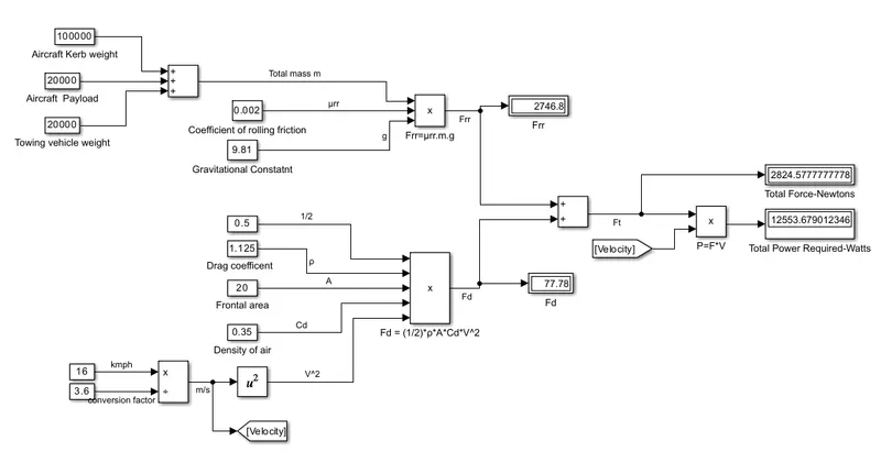
Model explanation:
- First we added aircraft kerb weight, payload weight and tow vehicle weight using constant blocks and addition block.
- Then it is multiplied with urr and g to get Frr which is connected to a display
- Given speed in km/h is converted to m/s using a correction value of 3.6 from a constant block and a product block(*/)
- Now along with speed in m/s ,other parameters are also fed to product block from different constant blocks to get Fd
- Total forces Frr and Fd are added an then multiplied with velocity using goto & From blocks Finally the resulted value P=F*V is displayed in a display block.
7. A). Design an electric powertrain with type of motor, it’s power rating, and energy requirement to fulfill aircraft towing application in Simulink. Estimate the duty cycle range to control the aircraft speed from zero to highest. Make all required assumptions. Prepare a table of assumed parameters. Draw a block diagram of powertrain.
(Hint :DC7 Block)
Ans.
Let us consider the following assumptions same as made in study 6A
Aircraft: Boeing 737-400
| Max ramp weight-m | 68,000kg |
| Wingspan area -A | 105.4 |
| Assumptions | |
| Coefficient of rolling resistance-μrr | 0.02 |
| Air density -ρ | 1.225 kg/ |
| Coefficient of drag -Cd | 0.019 |
| Towing time - t | 20 seconds |
Towing vehicle :Mototok Twin 7500
| Mass -m | 2,100kg |
| Frontal area -A (2.596m x 0.35m ) | 0.7476m^2 |
| Towing speed- V | 1.05m/s |
| Assumptions | |
| Coefficient of rolling resistance - μrr | 0.02 |
| Air density-ρ | 1.225kg/ |
| Coefficient of drag - Cd | 1.20 |
| Towing time - t | 20 seconds |
Hill climbing force : Fh = m.g Sinθ =0 considering a flat runway,
Calculated total traction force & power required to tow the aircraft from the available and assumed above data,
Fr=17,435.83N
P = F*V= 18,307.76W 18.3kW
so the motor should be minimum capacity of 18.3kW
How much torque the motor can produce is also a very important characteristic, hence before choosing a motor it is also necessary to know the rated torque needed by the towing vehicle to tow the aircraft:

where G - gear ratio of the transmission system
Mototok's ATS' are known to have extremely low gear ratios (around G = 27) to achieve the kind of massive torque needed to tow an aircraft of the size of Boeing 737-400
r = radius of the wheels; given as 0.15m
Assuming the efficiency of the gear transmission is 95%:
T=17435.83*0.15/(27*0.95) =101.96Nm
Pout=w*Tout. => 
ω=18,307.76/101.96 = 179.55 Rad/Sec =1714.65RPM
Now from the above data we have to select a motor from the available,
The motor selected keeping the above criterias in mind is 3-phase AC induction motor H-MA-MTS series:
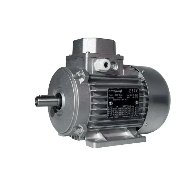
CHARACTERISTICS:
- Torque:Max.: 119.8 Nm (88.3599 ft.lb)
-
Min.: 0.46 Nm (0.3393 ft.lb)
- Power:Max.: 22 kW (29.912 hp)
-
Min.: 0.09 kW (0.122 hp)
- Rotational speed:Max.: 2,940 rpm (18,472.56 rad.min-1)
-
Min.: 630 rpm (3,958.41 rad.min-1)
Voltage rating : 480V
The motor needs to generate an output power of 18.3kW. Assuming the motor is 90% efficient:
the power input it needs to be supplied from the battery is calculated as,

Block diagram of powertrain:
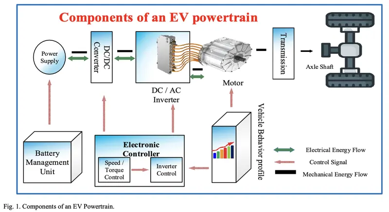
In the EV powertrain block diagram, we have alreday calculated motor ratings and looking back from the motor block, we have to provide the input power to the moto from the battery source via a power converter and power controller, consider these power converter and power controller are 100% efficient,
now we calculate the requirements of the battery:
Till now we made all calculations considering the aircraft is towing at a speed of 1.05m/s which is the maximum towing speed of the selected towing vehicle,
To move the aircraft at this speed , we have to operate the motor in tow vehicle at its full rated speed,
so now we'll calculate the ful-load current of the motor

where Pin= 20341.95 W
Vm.rated= 480V
PF - Power factor which is usually between 0.85-0.9, nwe consider as 0.87
so the full load current of the motor when it is running at full speed,which is to be provided by the battery(Ibat) via power converter is,

Power input from the battery is, Pi=Vbat*Ibat
=> 20341.95/28.12=Vbat
Vbat=723.39 V
Voltage supplied to the motor (here it is motor rated voltage 480V) Vo from the power converter is the input voltage Vbat*Duty cycle d
i.e, Vo = Vbat* d
d = 480/723.39 = 0.6635
So the power converter has to operate in between 0-0.6635 of duty cycle to control the speed of towing vehilce from zero to its rated highest speed.
Energy requirement of the battery:
E= Pi*t
Assuming the total time the battery needs to discharge its energy to the power converter and thus to the motor is 60 seconds (including the 20 seconds of towing at top speed of 1.05m/s):
E= 20341.96 * 60 = 1,220,517 Joules
Converting this into kWh, E= 1220517/ (1000*3600) = 0.339kWh
So the battery should be a minimum rating of 0.339kWh
From MATLAB help, we taken DC7 Four Quadrant chopper circuit and changed the DC source to Li-ion battery as shown in bellow simulink block diagam
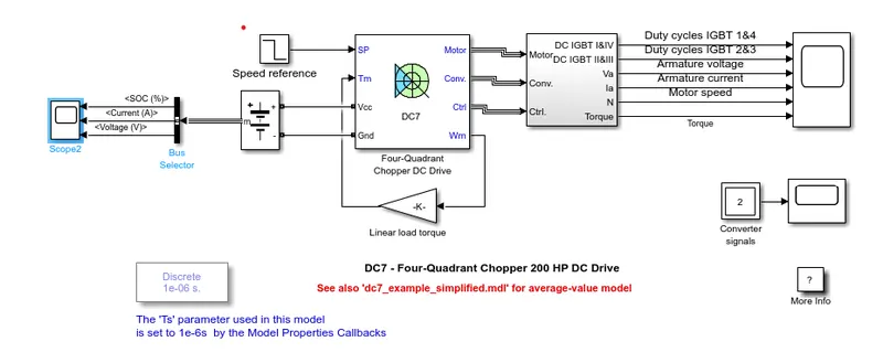
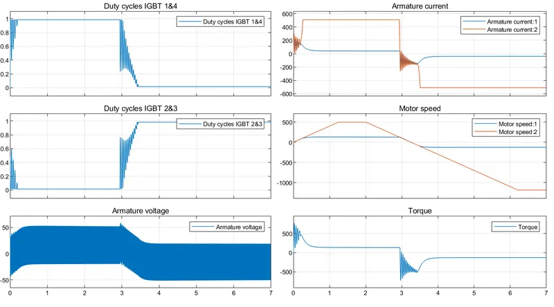
Simulating the above model for 7 sec, now we have the motor current and torque developed in bellow plot along with other details
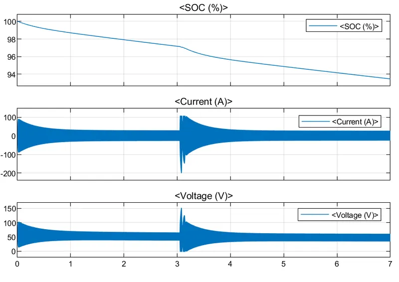
The connected lithium-ion battery has dropped its charge to 93.6% from 100% within 7sec with connected motor and load as given in the example.
7.B). Also, Design the parameters in excel sheet.
ANS.
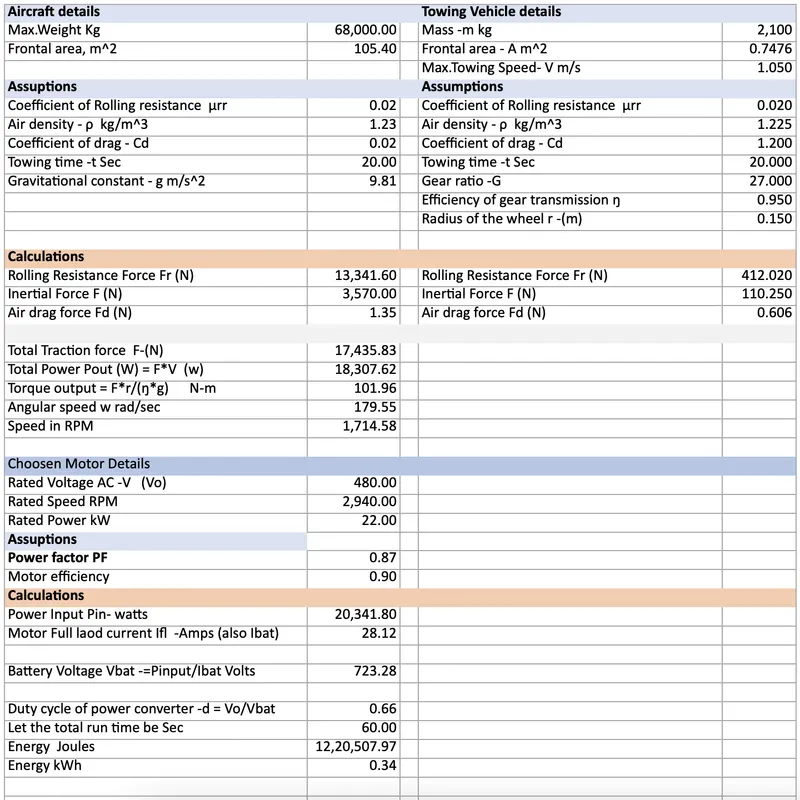
EXCEL FILE IS ATTACHED