Week-7 Challenge: DC Motor Control
1. A. Explain a MATLAB demo model named ‘Speed control of a DC motor using BJT H-bridge’.
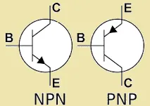
What is a Bipolar Junction Transistor (BJT)?
A bipolar junction transistor is a three-terminal semiconductor device that consists of two p-n junctions which are able to amplify or magnify a signal. It is a current controlled device. The three terminals of the BJT are the base, the collector, and the emitter. A signal of a small amplitude applied to the base is available in the amplified form at the collector of the transistor. This is the amplification provided by the BJT. Note that it does require an external source of DC power supply to carry out the amplification process.
Speed control of a DC motor using BJT H-bridge Model :
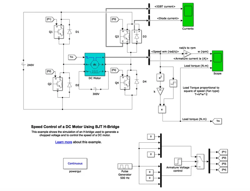
Description
The Bipolar Junction Transistor (BJT) when used for power switching applications, operates as an IGBT. When it is conducting (BJT operating in the saturated region), a forward voltage Vf is developed between collector and emitter (in the range of 1 V). Therefore, the IGBT block can be used to model the BJT device.
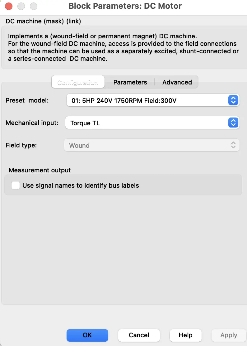
The IGBT block does not simulate the gate current controlling the BJT or IGBT. The switch is controlled by a Simulink® signal (1/0). The DC motor uses the preset model (5 HP 24V 1750 rpm). It simulates a fan type load (where Load torque is proportional to square of speed). The armature mean voltage can be varied from 0 to 240 V when the duty cycle (specified in the Pulse Generator block) is varied from 0 to 100%.
Note: The DC motor used in the simulink model is a separately excited DC motor and not a DC series motor. That is the reason why a DC voltage of 300V is given to the field windings.
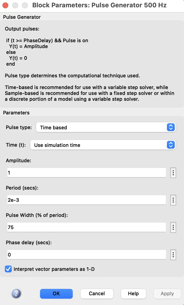
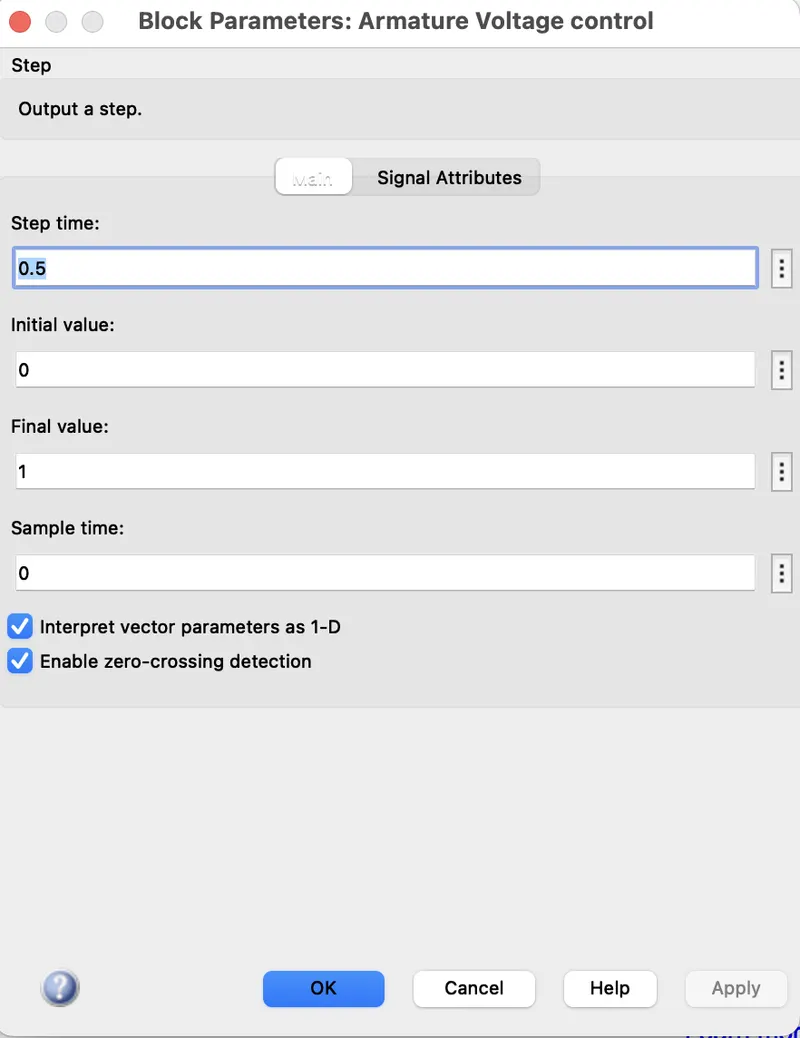
The H-bridge consists of four BJT/Diode pairs (BJT simulated by IGBT models). Two transistors are switched simultaneously: Q1 and Q4 or Q2 and Q3. When Q1 and Q4 are fired, a positive voltage is applied to the motor and diodes D2-D3 operate as free-wheeling diodes when Q1 and Q4 are switched off. When Q2 and Q3 are fired, a negative voltage is applied to the motor and diodes D1-D4 operate as free-wheeling diodes when Q2 and Q3 are switched off.
Simulation
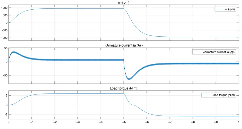
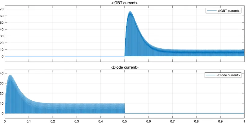
The motor starts in the positive direction with a duty cycle of 75% (mean DC voltage of 180V). At t= 0.5 sec., the armature voltage is suddenly reversed and the motor runs in the negative direction.
'Scope' shows motor speed, armature current and load torque and 'Currents' shows currents flowing in BJT Q3 and diode D3.
B. Comment on the armature current shoot-up from the scope results.
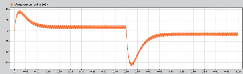
Initially, there is a spike in armature current. This is because, in a DC motor,
Ia=(V-Eb)/Ra
where Ia is the armature current, Vis the supply voltage , Eb is the back emf and Ra is the armature resistance.
At starting, Eb=0 as speed=0 at starting.
Therefore Ia=V/Ra and Ra is a very small value. Hence Ia is huge and that reflects in the graph.
We are able to control this current shoot by controlling the duty cycle or the pulse width of the pulse generator block, the resultant torque also varies accordingly.
C. Refer to the help section of ‘The Four-Quadrant Chopper DC Drive (DC7) block’. Compare it with the H-bridge model.
Four Quadrant Operation of any drives or DC Motor means that the machine operates in four quadrants. They are Forward motoring, Forward Braking, Reverse motoring and Reverse braking.
A motor operates in two modes – Motoring and Braking. A motor drive capable of operating in both directions of rotation and of producing both motoring and regeneration is called a Four Quadrant variable speed drive.
In motoring mode, the machine works as a motor and converts the electrical energy into mechanical energy, supporting its motion. In braking mode, the machine works as a generator and converts mechanical energy into electrical energy and as a result, it opposes the motion. The Motor can work in both, forward and reverse directions, i.e., in motoring and braking operations.
The product of angular speed and torque is equal to the power developed by a motor. For the multi-quadrant operation of drives, the following conventions about the signs of torque and speed are used. When the motor is rotated in the forward direction the speed of the motor is considered positive. The drives which operate only in one direction, forward speed will be their normal speed.
In loads involving up and down motions, the speed of the motor which causes upward motion is considered to be in forward motion. For reversible drives, forward speed is chosen arbitrarily. The rotation in the opposite direction gives reverse speed which is denoted by a negative sign.
The rate of change of speed positively in the forward direction or the torque which provides acceleration is known as Positive motor torque. In the case of retardation, the motor torque is considered negative. Load torque is opposite to the positive motor torque in the direction.
In the I quadrant power developed is positive and the machine is working as a motor supplying mechanical energy. The I (first) quadrant operation is called Forward Motoring.
II second quadrant operation is known as Braking. In this quadrant, the direction of rotation is positive, and the torque is negative, and thus, the machine operates as a generator developing a negative torque, which opposes the motion.
The kinetic energy of the rotating parts is available as electrical energy which may be supplied back to the mains. In dynamic braking, the energy is dissipated in the resistance.
The III third quadrant operation is known as the reverse motoring. The motor works, in the reverse direction. Both the speed and the torque have negative values while the power is positive.
In the IV fourth quadrant, the torque is positive, and the speed is negative. This quadrant corresponds to the braking in the reverse motoring mode.
DC7 - Four-Quadrant Chopper 200 HP DC Drive:
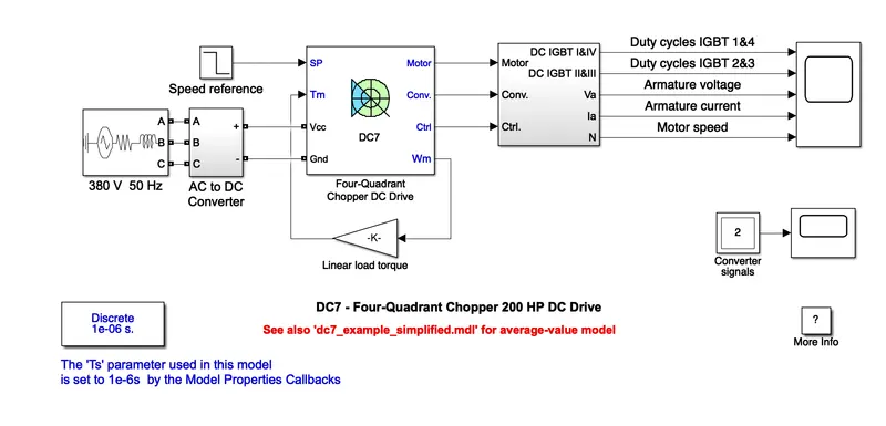
Four-Quadrant Chopper DC Drive:
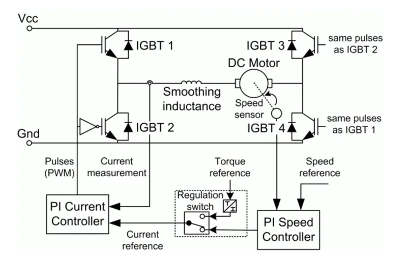
Description
The 200 HP DC motor is separately excited with a constant 150 V DC field voltage source. The armature voltage is provided by an IGBT converter controlled by two PI regulators. The converter is fed by a 515 V DC bus obtained by rectification of a 380 V AC 50 Hz voltage source. In order to limit the DC bus voltage during dynamic braking mode, a braking chopper has been added between the diode rectifier and the DC7 block.
The first regulator is a speed regulator, followed by a current regulator. The speed regulator outputs the armature current reference (in p.u.) used by the current controller in order to obtain the electromagnetic torque needed to reach the desired speed. The speed reference change rate follows acceleration and deceleration ramps in order to avoid sudden reference changes that could cause armature over-current and destabilize the system. The current regulator controls the armature current by computing the appropriate duty ratios of the 5 kHz pulses of the four IGBT devices (Pulse Width Modulation). For proper system behaviour, the instantaneous pulse values of IGBT devices 1 and 4 are opposite to those of IGBT devices 2 and 3. This generates the average armature voltage needed to obtain the desired armature current. In order to limit the amplitude of the current oscillations, a smoothing inductance is placed in series with the armature circuit.
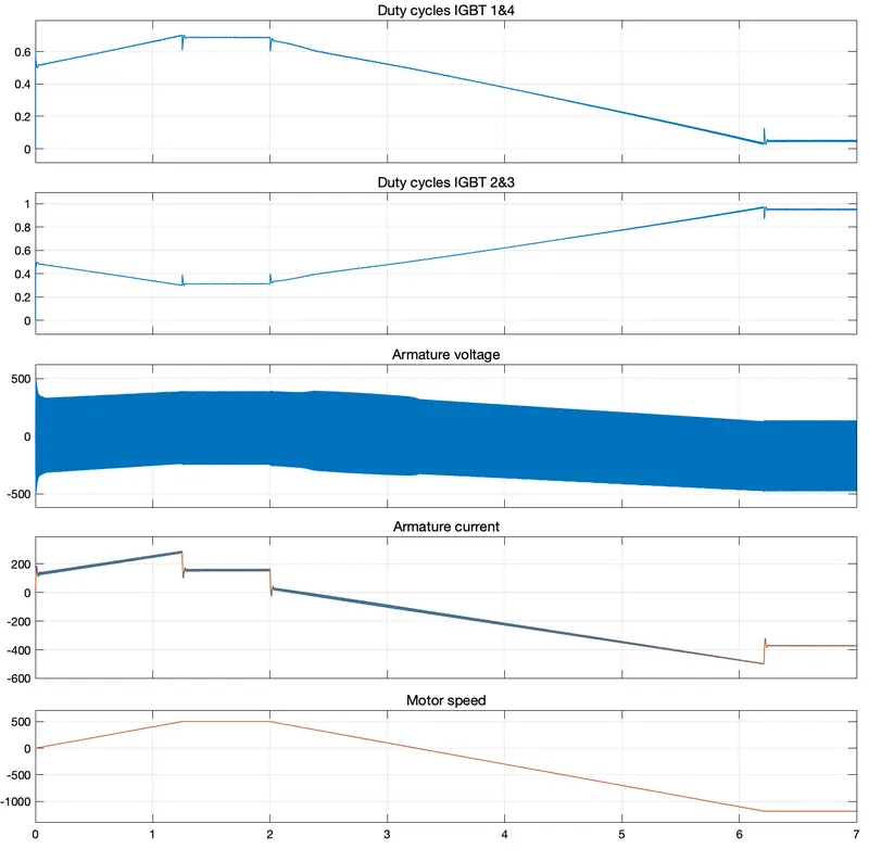
SCOPE OUTPUT:
Simulation
Before starting the simulation, set the initial bus voltage to 515 V via the GUI block ('Initial States Setting' button and 'Cbus' variable).\
Start the simulation. You can observe the motor armature voltage and current, the four IGBT pulses and the motor speed on the scope. The current and speed references are also shown.
The motor is coupled to a linear load, which means that the mechanical torque of the load is proportional to the speed.
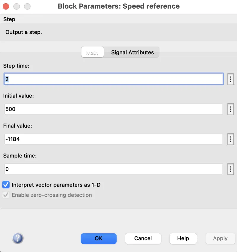
The speed reference is set at 500 rpm at t = 0 s. Observe that the motor speed follows the reference ramp accurately (+400 rpm/s) and reaches steady state around t = 1.3 s.
The armature current follows the current reference very well, with fast response time and small ripples. Notice that the current ripple frequency is 5 kHz.
At t = 2 s, speed reference drops to -1184 rpm. The current reference decreases to reduce the electromagnetic torque and causes the motor to decelerate with the help of the load torque.
At t = 2.2 s, the current reverses in order to produce a braking electromagnetic torque (dynamic braking mode). This causes the DC bus voltage to increase.
At t = 3.25 s, the motor reaches 0 rpm and the load torque reverses and becomes negative. The negative current now produces an accelerating electromagnetic torque to allow the motor to follow the negative speed ramp (-400 rpm/s). At t = 6.3 s, the speed reaches -1184 rpm and stabilizes around its reference.
Notes
1) The power system has been discretized with a 1 us time step. The speed and current controllers use a 100 us and 20 us sampling time respectively in order to simulate a microcontroller control device.
2) In order to reduce the number of points stored in the scope memory, a decimation factor of 25 is used. Some transitions may thus not appear on the scope. To view detailed simulation results, reduce the decimation factor to 1.
3) A simplified version of the model using an average-value converter can be used by selecting 'Average' in the 'Model detail level' menu of the graphical user-interface. The time step can then be increased up to the smallest control system sample time value. This can be done by typing 'Ts = 20e-6' in the workspace in the case of this example. See also dc7_example_simplified model.
|
Four-Quadrant Chopper DC Drive (DC7) block |
H-bridge model |
| here the motor can be oprated in 4 signals are different modes | is used for changing the direction of motor |
| regenarative braking can be achieved | regenerative braking cannot be available |
| the source is an AC supply which can be rectified to dc varying supply | the source is of fixed dc supply |
| the armature current doesn't shoot up to the vehicle of BJT H-bridge | the armature current shoots up during the phase transition |
| signals are not contineous and they are discrete | signals are contineous |
| better control of vehicle | less control of vehicle |
2. Develop a 2-quadrant chopper using simulink & explain the working of the same with the relevant results. (Refer to article - Multiquadrant operation of motor )
Two-quadrant choppers
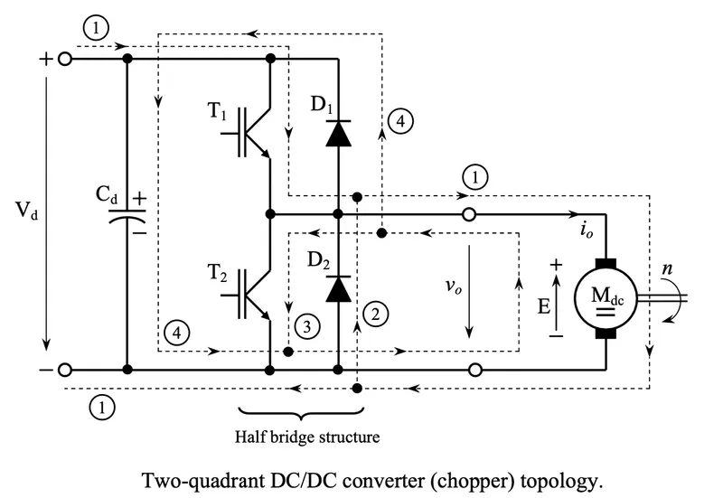
The two-quadrant chopper topology includes two controllable semiconductor devices (transistors) with antiparallel recovery (freewheeling) diodes, forming the well known bridge leg structure named half bridge. The way in which the half bridge structure used for a two-quadrant chopper is connected to the supply DC voltage Vd and to the load (DC motor) is presented in Fig. bellow.
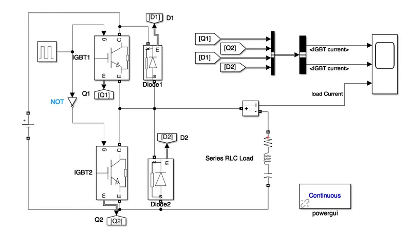
Simulink Model for a TWO-QUADRANT CHOPPER:
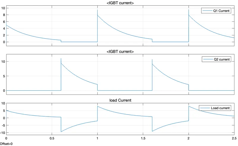
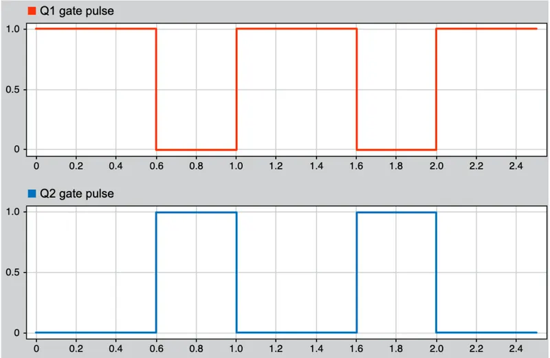
When IGBT1 is On and IGBT2 is Off, voltage across the load is positive and load current is positive (Source-IGBT1_Load)
When IGBT1 is Off and IGBT2 is ON , voltage across the load reveses due to stored enrgy in it and the load current direction reverses. (IGBT2-ammeter-IGBT2_load)
3. Explain in a brief about operation of BLDC motor
BRUSHLESS DC (BLDC) MOTOR :-
A brushless DC electric motor(BLDC), also known as electronically commutated motor or synchronous DC motor, is a synchronous motor using a direct current electric power supply. A BLDC motor also known as permanent magnet synchromous motor(PMSM). There are two types of BLDC motors are present 1. 3-phase trapezoidal BLDC motor, 2. sinusidal type BLDC motor. Most of the BLDC motors are 3-phase type.
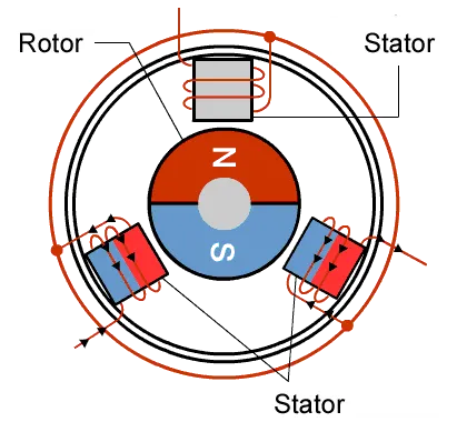
As shown in the above figure the BLDC motor has only two basic parts, rotor and stator. The rotor is the rotating part and has rotor magnets whereas stator is the stationary part and contains stator windings. In BLDC permanent magnets are attached in the rotor and move the electromagnets to the stator. The high power transistors are used to activate electromagnets for the shaft runs. The performance power distribution by using a solid-state circuit.
OPERATION :
There are 3 windings as you can see in the below image. Each of these phases are electrically 120 degrees apart from each other. The winding around the stator are wound such that current enters from the source an leaves back to complete the circuit.
The decoder circuit works such that the 3 phases are active 120 degrees apart, as you can see in the below diagram.
ADVANTAGE OF BLDC MOTOR :
- The absence of brushes reduces the frequent replacement of brushes which reduces the maintenance cost.
- A Brushless DC motor has high-level control over the speed and position of the motor.
- The lifespan of a Brushless DC motor is higher than the brushed DC motor.
- Sparking is reduced due to the absence of brushes and there is a few chances of burnout due to sparking issues.
- A Brushless DC motor provides high torque to speed ratio which is best suited for robotics and medical applications.
- As there is no electromagnet in the Brushless DC motor hence the heating issue is being reduced.
- These motors are suitable to run either in a low load or no-load.
- As there are no brushes it produces less operating noise.
- These motors are used in electrical applications where less noise is required.
DISADVANTAGE OF BLDC MOTOR :
- Brushless DC motors are operated at relatively low speeds. Due to this low-speed vibrations occurs in the system.
- The cost of these motors is high.
- As these motors consist of a feedback loop the wiring and operation are not that simple.
- It requires an electronic switching controller to switch the voltage to the motor coils.
- As the Brushless DC motor doesn’t consist of the commutator, it will require some special electronic device.
- It needs three hall effect sensors to measure rotor position.
APLLICATION OF BLDC MOTOR:
- Brushless DC motors are used in hybrid vehicles, electric vehicles, and other electrical equipment.
- These motors are used in robotics for robotic arms.
- BLDC motors are used in computer hard drives and DVD players.
- These motors are used in fans, washing machines, dryers, pumps, blowers, and compressors.