Project-1: Modelling an electric Car with Li-ion battery
Create a MATLAB model of electric car which uses lithium ion battery and suitable motor. Choose suitable blocks from Simscape or Powertrain block set. Implement the vehicle speed control using PI controller and generate brake and accelerator commands. Avoid using readymade driver block for speed control.
Prepare a report about your model including following:
Objectives, System level configurations, Model parameters, Results, Conclusion.
(Note- The simulink model file should be compulsorily attached)
OBJECTIVES:
To develop a MATLAB model of electric car which runs on lithium-ion battery and suitable motor and using suitable blocks from Simscape or Powertrain block set.
To include a PI controller based vehicle speed controller in the model to generate brake and accelerator commands. (without using readymade driver block for speed control).
Selecting appropriate parameters for various blocks of electric vehicle and understanding their characteristics the preliminary step in modeling a good electric vehicle. This challenge presents the study of vehicle parameters based on simulation of electric vehicle. All works are performed in MATLAB/Simulink environment.
Keywords: Electric vehicle, vehicle parameters, simulation, MATLAB/Simulink
INTRODUCTION
Nowadays, the trend of reducing energy consumption and environmental impact has led to the electrification of vehicle for future transportation. The serious issue of global warming, also known as the greenhouse effect, urban pollution, and the depletion of fossil fuels have increased the worldwide tensions. Although the Internal Combustion Engine (ICE) technology is being matured over the past 100 years, it will mainly rely on improving the fuel economy and reduce emissions.
Electric vehicles or EVs are the type of vehicles that are partially or fully powered by electric power. The provide the advantage of zero emissions, eco-friendly, low running and maintenance costs etc. Electric vehicles are the key to sustainable transport.
However, the main challenges to solve in EV are battery-related issues; the high initial cost, limited driving range, and long charging time of its battery. The battery must contain sufficient energy to drive certain range and provide enough power during accelerations. In order to estimate and optimize the energy consumption of EV, we need to model an EV. It is important to have a good model of EV to prevent wrong conclusions.
The classification is based on the type of mechanism used for energy production. The types of electric vehicles are :
- Battery Electric Vehicle (BEV)
- Hybrid Electric Vehicle (HEV)
- Plug-in Hybrid Electric Vehicle (PHEV)
- Fuel Cell Electric Vehicle(FCEV)
Here we are going to discuss about BEV only,
1.Battery Electric Vehicle (BEV)
In Battery Electric Vehicle (BEV) all the energy required to run the electric motor comes from the battery pack. Use of gasoline is absent. Therefore, they emit zero emissions and are eco-friendly. They do not need a reduction gearbox. The battery can be charged from 10% to 80% in around 30 minutes with DC fast charging.
Advantages
- They are quiet. Since, there is no internal combustion noise.
- Safe to operate and charge
- Eco-friendly
Disadvantages
- Not ideal for long distance drive
- Charging time can take up to hours
- Difficult to locate charging station
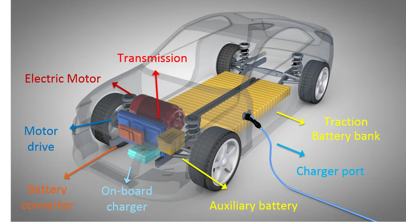
Electric vehicles consists of an electric motor that is powered by a battery pack. The main advantage of electric vehicles is that they emit zero emissions and are eco-friendly. They also do not consume any fossil fuels, hence use a sustainable form of energy for powering the car. The main components of electric vehicles are :
- Traction battery pack
- DC-DC Converter
- Electric motor
- Power inverter
- Charge Port
- Onboard charger
- Controller
- Auxiliary batteries
- Thermal system (cooling)
1.Traction battery pack
Traction battery pack is also known as Electric vehicle battery (EVB) . It powers the electric motors of an electric vehicle. The battery acts as an electrical storage system. It stores energy in the form DC current. The range will be higher with increasing kW of the battery. The life and operation of the battery depends on its design. The lifetime of a traction battery pack is estimated to be 200,000 miles.
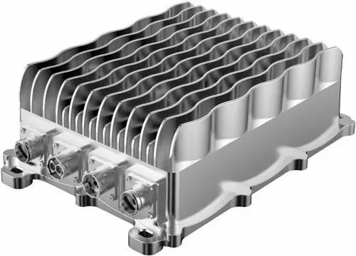
2.DC-DC Converter
The traction battery pack delivers a constant voltage. But different components of the vehicle has different requirements. The DC-DC convertor distributes the output power that is coming from the battery to a required level. It also provides the voltage required to charge the auxiliary battery.
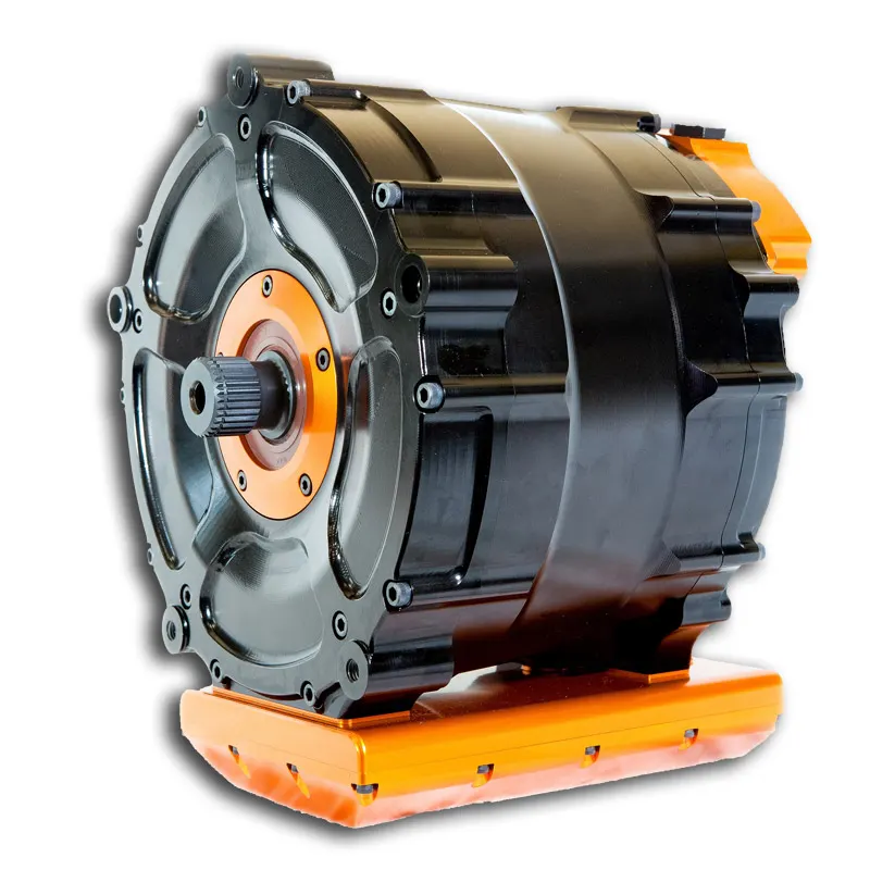
3.Electric motor
Electric traction motor is the main components of electric vehicle. The motor converts the electrical energy into kinetic energy. This energy rotates the wheels. Electric motor is the main component that differentiates an electric car from conventional cars. An important feature of an electric motor is the regenerative braking mechanism. This mechanism slows down the vehicle by converting its kinetic energy into another form, and storing it for future use. There are basically two types of motors DC and AC motors.
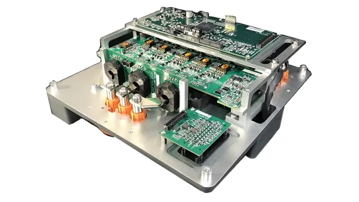
4.Power Inverter
It coverts DC power from the batteries to AC power. It also converts the AC current generated during regenerative braking into DC current. This is further used to recharge the batteries. The inverter can change the speed of the motor.
5. Charge Port
The charge port connects the electric vehicle to an external supply. It charges the battery pack. The charge port is sometimes located in the front or rear part of the vehicle
6.Onboard charger
Onboard charger is used to convert the AC supply received from the charge port to DC supply. The on board charger is located and installed inside the car. It monitors various battery characteristics and controls the current flowing inside the battery pack.
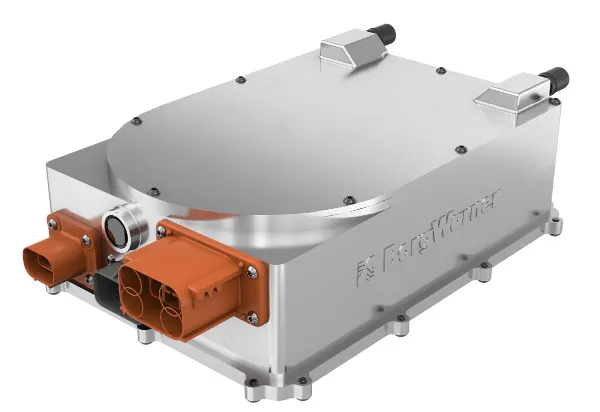
7.Controller
Power electronics controller determines the working of an electric car. It performs the regulation of electrical energy from the batteries to the electric motors. The pedal set by the driver determines the speed of the car and frequency of variation of voltage that is input to the motor. It also controls the torque produced.
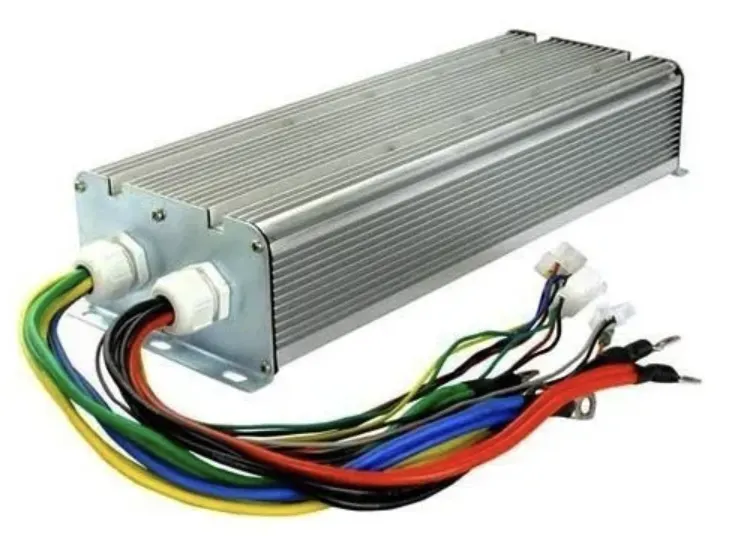
8.Auxiliary batteries
Auxiliary batteries are the source of electrical energy for the accessories in electric vehicles. In the absence of the main battery, the auxiliary batteries will continue to charge the car. It prevents the voltage drop, produced during engine start from affecting the electrical system.
9. Thermal system(cooling)The thermal management system is responsible for maintaining an operating temperature for the main components of an electric vehicle such as, electric motor, controller etc. It functions during charging as well to obtain maximum performance. It uses a combination of thermoelectric cooling, forced air cooling, and liquid cooling.
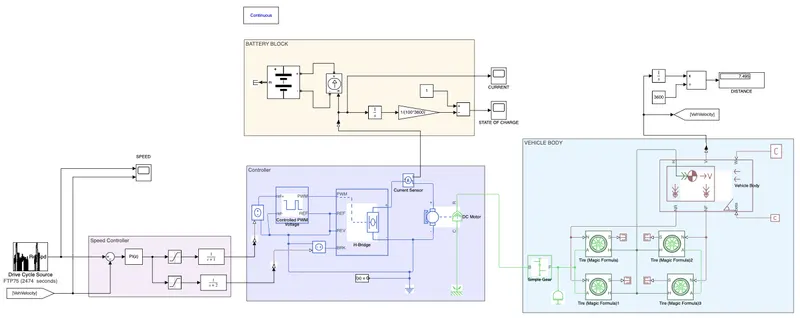
This block diagram is devided in to 5 major sections,
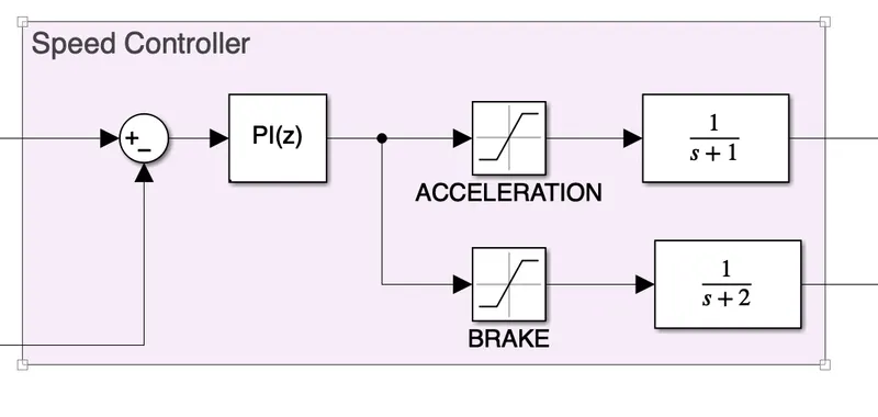
1) Drive cycle input, 2) Speed controller, 3) Electronic circuit and motor, 4) Battery Block and 5) vehcile body
Model parameters:
Now we'll look into various blocks and their parameters
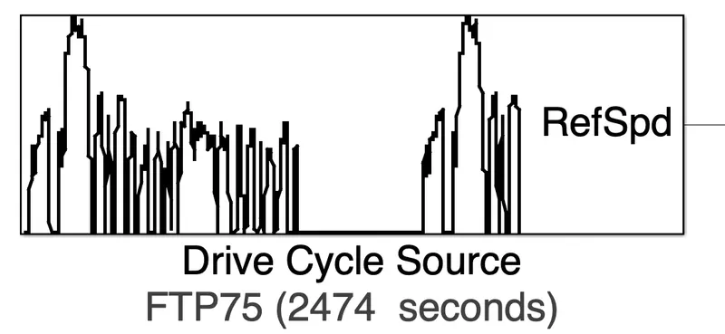
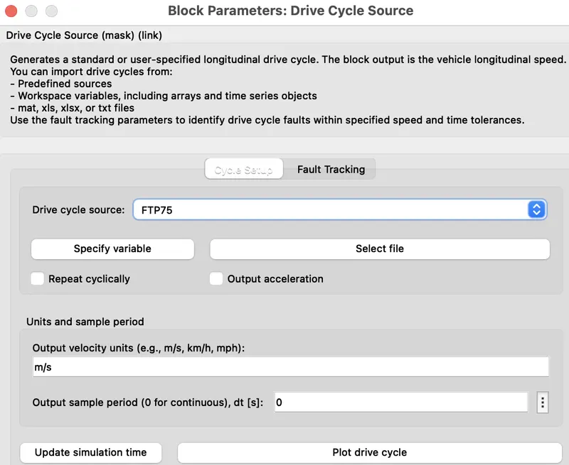
1) Drive cycle input:
2) Speed controller:
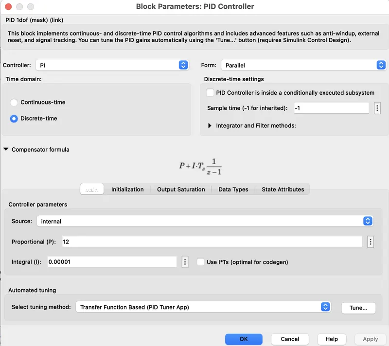
PID Controller-
The EV model's speed control depends on the PID controller block. The PID controller block attempts to reduce the error data between the drive cycle data and the actual speed of the vehicle (which it receives from the sum block).
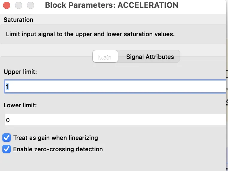
Acceleration-
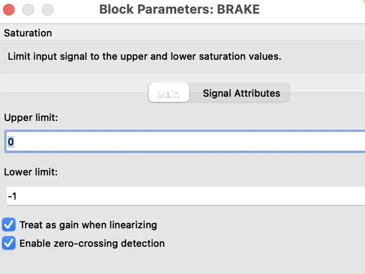
Brake
Transfer Function-
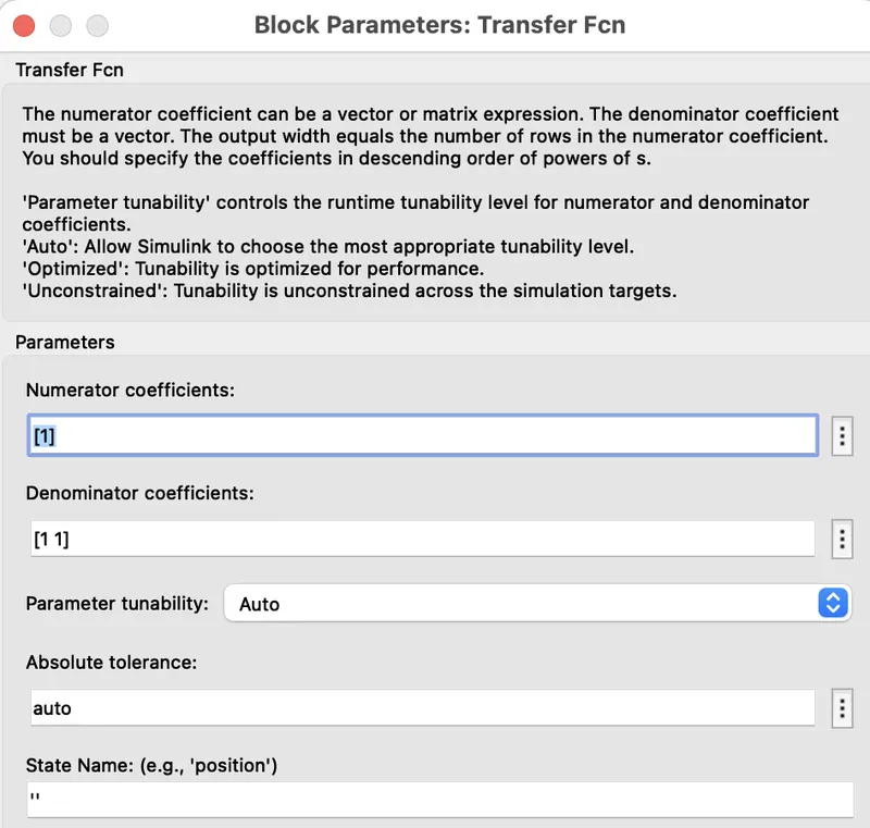
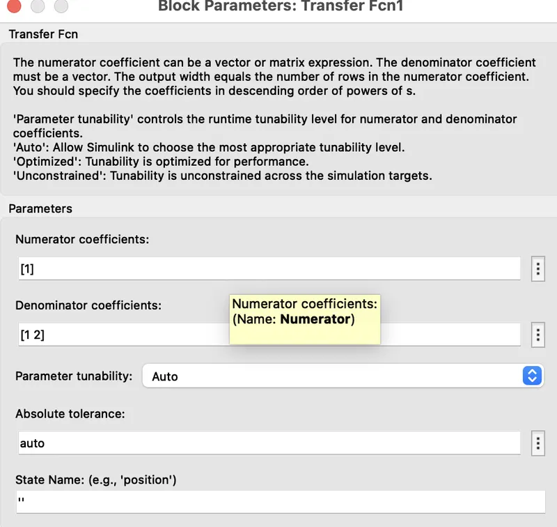
The transfer function block is used when we want to insert a transfer function. A transfer function is defined as the ratio of the Laplace transform of the output of a system to the input of a system.
3) Electronic circuit and motor:
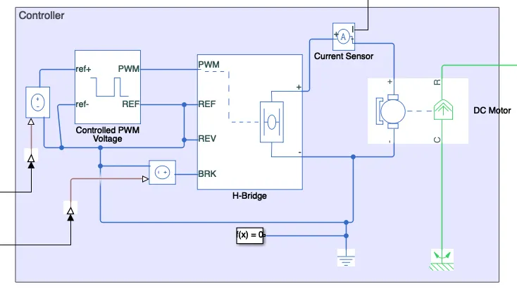
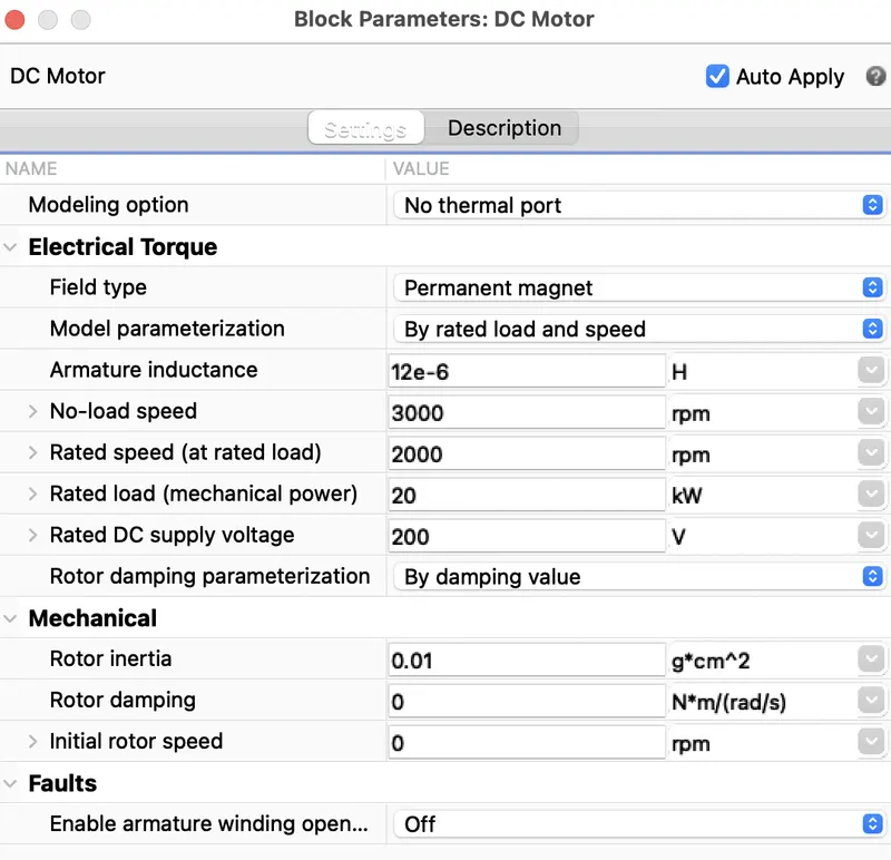
DC Motor(Brushed Type)
The block assumes that no electromagnetic energy is lost, and hence the back-emf and torque constants have the same numerical value when in SI units. Motor parameters can either be specified directly, or derived from no-load speed and stall torque. If no information is available on armature inductance, this parameter can be set to some small non-zero value.
When a positive current flows from the electrical + to - ports, a positive torque acts from the mechanical C to R ports. Motor torque direction can be changed by altering the sign of the back-emf or torque constants.
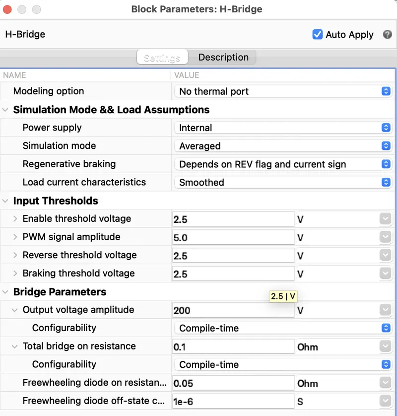
H-Bridge-
This block represents an H-bridge motor drive. The block can be driven by the Controlled PWM Voltage block in PWM or Averaged mode. In PWM mode, the motor is powered if the PWM port voltage is above the Enable threshold voltage. In Averaged mode, the PWM port voltage divided by the PWM signal amplitude parameter defines the ratio of the on-time to the PWM period. Using this ratio and assumptions about the load, the block applies an average voltage to the load that achieves the correct average load current.
For this model, Averaged mode is selected.
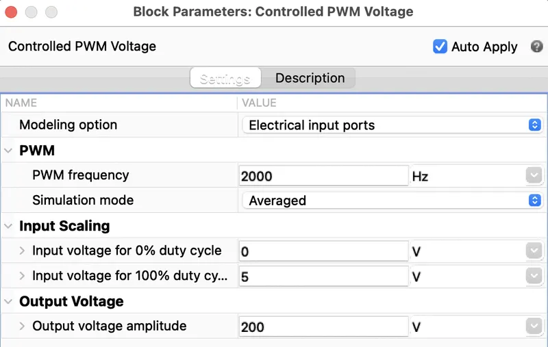
Controlled PWM Voltage-
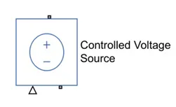
Controlled Voltage Source-
The block represents an ideal voltage source that is powerful enough to maintain the specified voltage at its output regardless of the current passing through it. The output voltage is V = Vs, where Vs is the numerical value presented at the physical signal port.
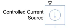
Controlled Current Source-
Converts the Simulink input signal into an equivalent current source. The generated current is driven by the input signal of the block.
4) Battery Block:
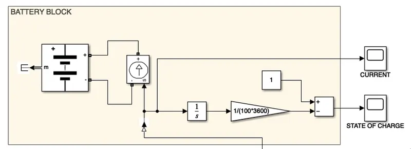
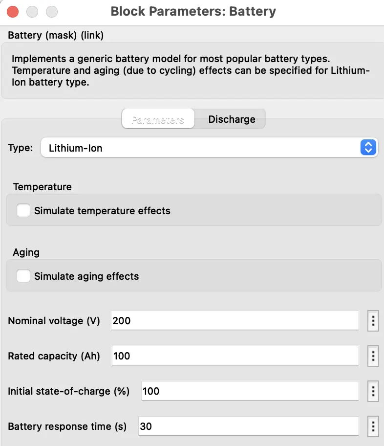
Battery-
5) vehcile body:
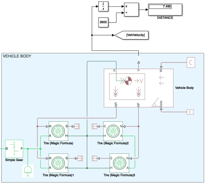
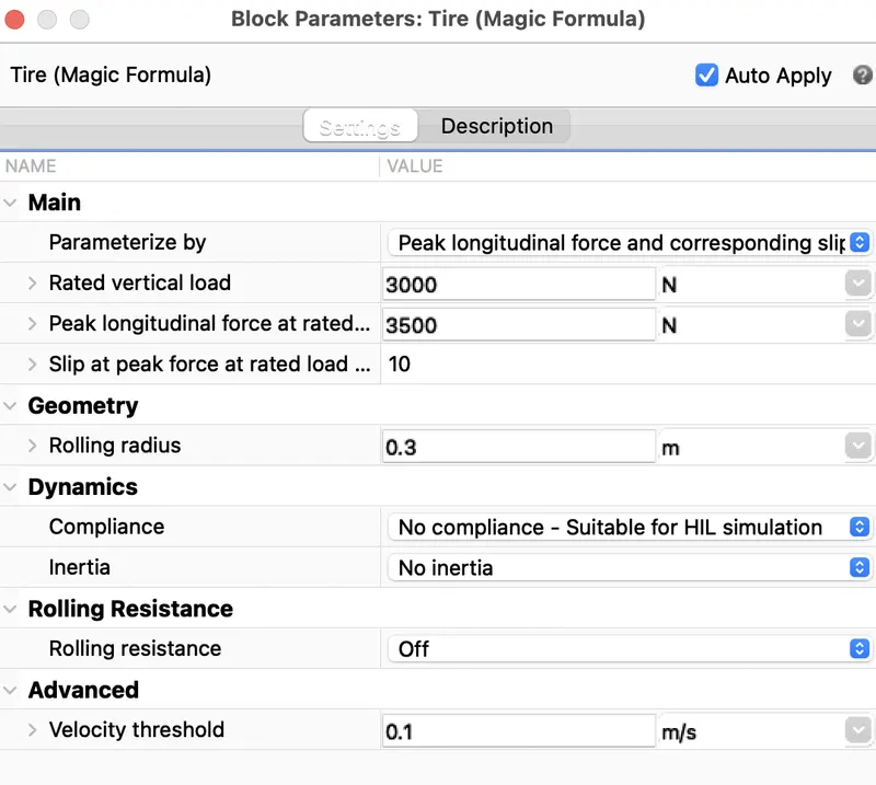
Tire (magic formula) block represents the longitudinal behavior of a highway tire characterized by the tire Magic Formula. The block is built from Tire-Road Interaction (Magic Formula) and Simscape Foundation Library Wheel and Axle blocks. Optionally, the effects of tire inertia, stiffness, and damping can be included.
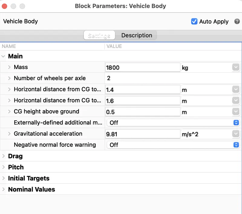
Vehicle body Block:
Represents a two-axle vehicle body in longitudinal motion. The block accounts for body mass, aerodynamic drag, road incline, and weight distribution between axles due to acceleration and road profile. The vehicle can have the same or a different number of wheels on each axle. Optionally include pitch and suspension dynamics or additional variable mass and inertia. The vehicle does not move vertically relative to the ground.
Connection H is the mechanical translational conserving port associated with the horizontal motion of the vehicle body. Connections V, NF, and NR are physical signal output ports for vehicle velocity and front and rear normal wheel forces, respectively. Connections W and beta are physical signal input ports corresponding to headwind speed and road inclination angle, respectively. M represents the additional mass. If both variable mass and pitch dynamics are included, the physical signal port J accepts the inertia of the additional mass about its own CG.
Gear-
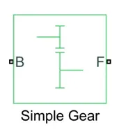
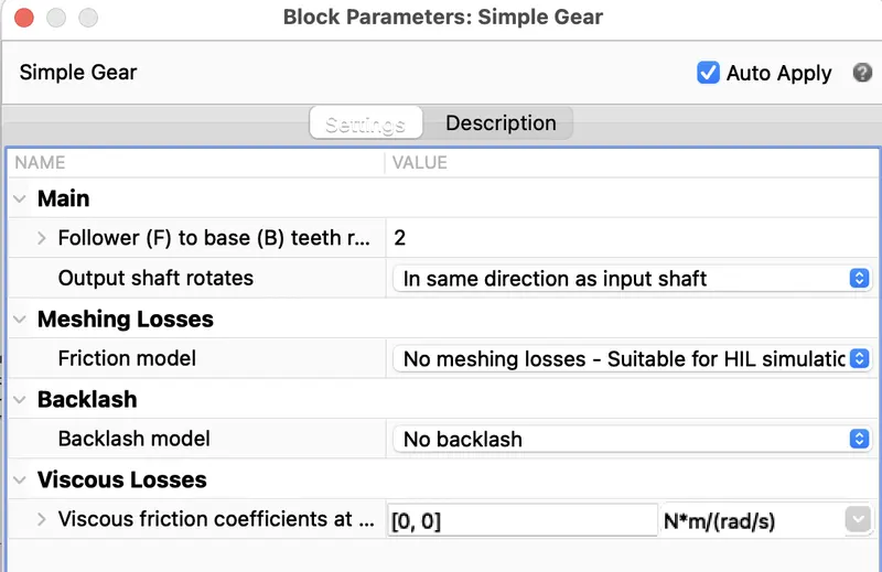
A Simple Gear block with a set gear ratio and no inertial effects to streamline the transmission system of the EV model.
Inertia:
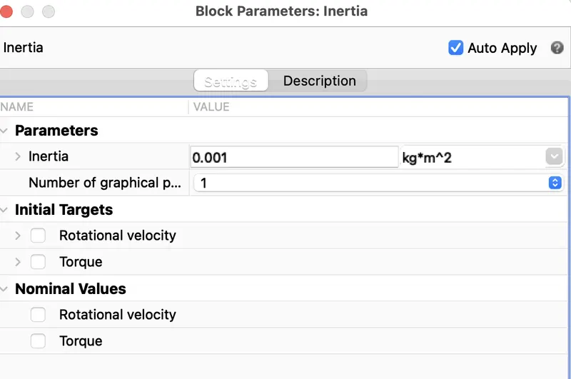
The block represents an ideal mechanical rotational inertia.
Powergui Block:
Results:
With Drive cycle FTP75:
(Untuned PI controller)
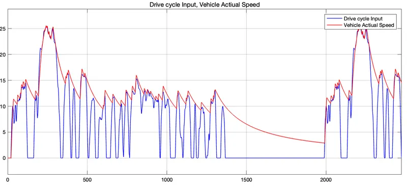
we can see the blu one as velocity reference from drive cycle source and the red one is vehicle velocity in which it almost synced to it but when deceleration or brake command is applied, it is applying only to the motor which is called electrical braking if mechanical braking is also added to the vehicle body which synchronised with the brake command the velocity reference from the drive cycle source and vehicle velocity got synced 100%.
Current:
Battery SOC:
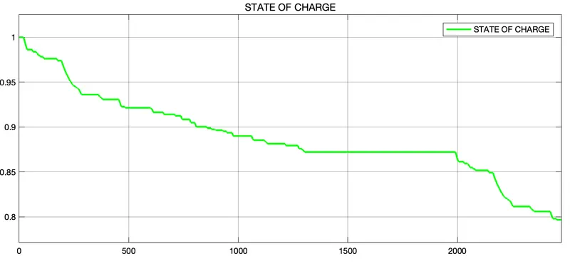
we are seeing the battery SOC % in which it dropped from 100% to neaarly 78% which is meant that battery consumed 22% for the distance of 7.935miles
Conclusion:
An electric car with suitable motor and lithium battery with an PI controller is designed in SIMULINK, and also simulated with standard drive cycle as a velocity reference for PI controller in which we acheived the electrical braking and the vehicle velocity synced almost 70% to the velocity reference because of the capacity of the motor it immediently accelerating as the dc motor has the high torque so if we apply mechanical brakes synchronisig with the PI controller we can achieve 100% sync with the velocity reference.
A simple and low run-time vehicle model using PI controller, brake and accelerator commands avoidng readymade driver block for speed control.
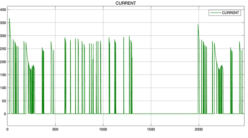
The SOC, current in the vehicle battery is observed.
The design for an electric vehicle is modelled. Further, the controlling part can be optimised with improved with control gains.
References :