Final Project: Electric Rickshaw modelling
Aim: To Create a detailed MATLAB model of an electric rickshaw (three wheel passenger vehicle) as per details below
Main objectives:
To develop a rear wheels driven Electric rikshaw model by PM brushed type motor and assuming efficiency points of motor controller and motor
To prepare an excel sheet of all input and assumed data
Results: To show energy consumption for any three standard driving cycles , temperature rise of motor and controller for 100 km constant speed driving at 45 kmph
ABSTRACT:
This topic presents model of the ELECTRIC RICKSHAW by using a PM brushed type DC motor and a suitable Lithium-Ion battery for the motor. Before that, we will know about what is Electric Rickshaw, how it's works and the benefits of EV RICKSHAW. Then we make an actual EV RICKSHAW model in SIMULINK with suitable block set. here main motto is to check how the modeled RICKSHAW performs for any three standard driving cycles showing energy consumption, the temperature rises of motor and controller for vehicle cover around 100 km at constant speed driving 45 kmph.
1.INTRODUCTION: Electric vehicles are now in revolutionary phase in India, but not so significantly in cars Electric rickshaws are popular in several cities of India, human effort compared to pedal rickshaws. They are well accepted as an alternative to combustion engine-powered rickshaws and pedal rickshaw. An electric rickshaw offers a cheaper and eco-friendl transport facility to the low-income people.
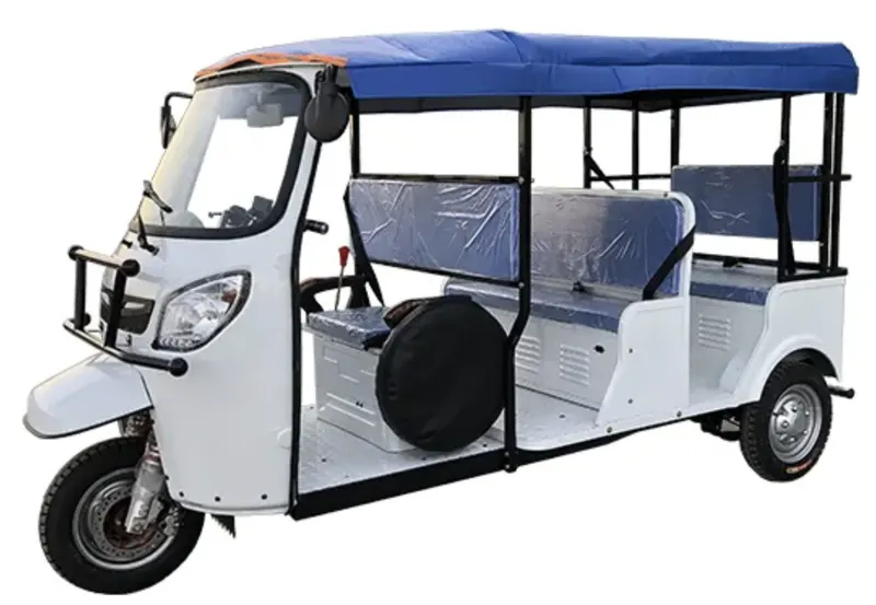
Fig.1 E-Rickshaw
Particularly battery electric vehicle such as electric rickshaw (e-rickshaw) has the benefits of high energy efficiency and zero-tailpipe emissions which are suitable for short distance commute within the city.
BENEFITS OF E-RICKSHAW
There are many benefits to switching from a fuel-run auto to an E-Rickshaw. These include-
- Lower maintenance
- More cost-effective in the long run
- Savings on fuel prices
- Good for the environment
- Various government and tax incentives
The major reasons for the rise of e-rickshaw are:
1. They require lower investment than an Auto-Rickshaw and quite pleasing daily earnings than cycle rickshaws.
2. They have lower running cost as E-Rickshaw charging is easily available with conventional single phase socket at home and low operating cost model for rickshaw owners.
3. E-Rickshaw is one of the best options for passengers for quick, safe and cost effective last mile connectivity.
4. They provide mass scale employment and good source of income to the traditional rickshaw puller. These three-wheeled vehicles play the most important role as public, private and para-transit modes of transportation and they are suited to the Indian traffic environment. They play a fundamental role in the Indian auto industry. They are small and narrow, allowing maneuverability on congested roads. Despite the apparent advantages in the vehicle design, auto rickshaws present a huge pollution problem in major Indian cities. This is due to poor vehicle maintenance and the use of an inefficient engine with very little pollution control.
2. BLOCK DIAGRAM:
Electric Motor: It is controlled via an electronic controller. PMDC motors do not require field winding, thus, they do not have field circuit copper loss. PMDC motors have higher efficiency as compared to conventional DC motors. Since field winding are not used in PMDC motors, hence, these motors are compact in sized than conventional DC motors.
Electronic Motor Controller: Electrical E-rickshaw controller is one of the main component of the battery powered vehicle that governs its complete operation. The controller includes a manual or automatic switch turning the motor on/off, selecting forward or reverse motion, selecting and regulating speed.
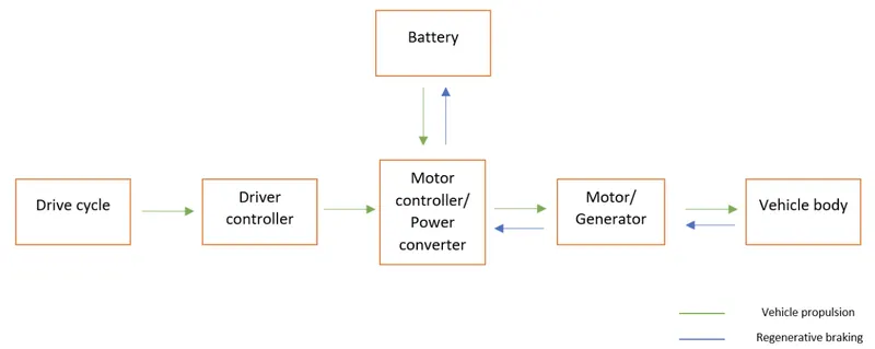
Fig.2 EV Block diagram
Battery: For EV applications and areas that require a long-lasting power supply, a lithium-ion battery would be the ideal option.
*Brakes, Steering, Front Suspension, Rear Suspension, Differential are also some major parts of the E-rikshaw.
Speedometer/Indicator: Speedometer generally used have analog dials. The one the left side indicates vehicle speed and one on the right side indicate battery charge level. It is connected to the controller unit.
DC to DC Converter: Practical electronic converters use switching techniques. Switched mode DC-to-DC converters convert one DC voltage level to another, which may be higher or lower, by storing the input energy temporarily and then releasing that energy to the output at a different voltage. It is designed to fulfill dc power requirement of e-rickshaw vehicle. Light weight, which allows to move from one place to another place. Input reverse connection protection.
Miscellaneous Spare parts: Centre locking, Alloy wheel, Rear light, Front glass, Front Indicator, Head light, Ignition switch, Charger, Converter, left-right switch, Type, Wirings, Throttle set etc
3. WORKING PRINCIPAL OF ELECTRIC RICKSHAW
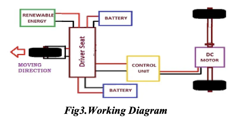
Working of E-Rickshaw is based on DC motor, battery & suspension system different from conventional auto rickshaws. Here it uses a PMDC motor with a differential mechanism at rear wheels. It consists of the controller unit. The battery used is mostly Lead acid/Li-ion battery with a life of 6-12 months. Deep discharge/cycle batteries designed for EVs are mostly used.
MATLAB SIMULINK MODEL BLCOK DIAGRAM OF ERIKSHAW:
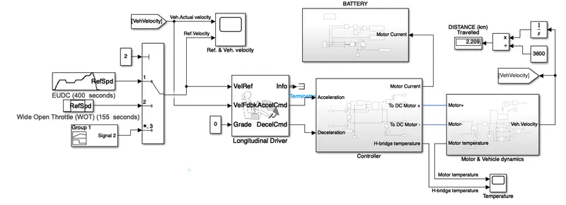
Initially the current flows to DC Motor from the battery through the DC-DC power converter to drive the motor. The required voltage will be controlled in the controller. The Controller will follow the given drive cycle reference and run the motor in the required rpm. Then the motor power is transmitted to the wheels of a vehicle through the gear box. and the controller will take the vehicle speed and compare and controlled.
Model parameters:
Drive cycle:
A driving cycle is a series of data points representing the speed of a vehicle versus time. they are used in propulsion system simulations to predict performance of internal combustion engines, transmissions, electric drive systems, batteries, fuel cell systems, and similar components.
Here we are using two standard drive cycle and one user drive cycle,
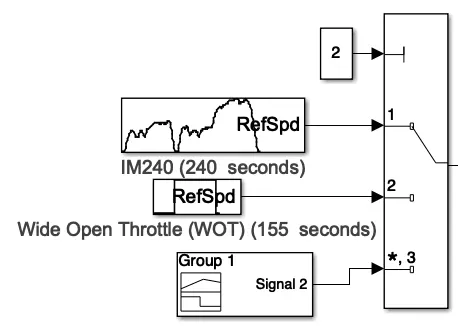
- The IM240 test is a chassis dynamometer schedule developed and recommended by the US EPA for emission testing of in-use light duty vehicles in inspection & maintenance (I&M) programs implemented in a number of states. The EPA has also developed a guidance document specifying IM240 emission standards for use in I&M emission testing programs
- Wide open throttle(WOT), also called full throttle, is the fully opened state of a throttle on an engine
- As a 3rd driving cycle here inputed user drive cycle from signal builder block for 8000sec duration with constatnt speed of 45kmph which covers a total 100km during its duration
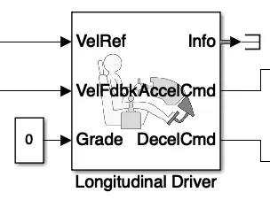
Driver Controller/Longitudinal driver:
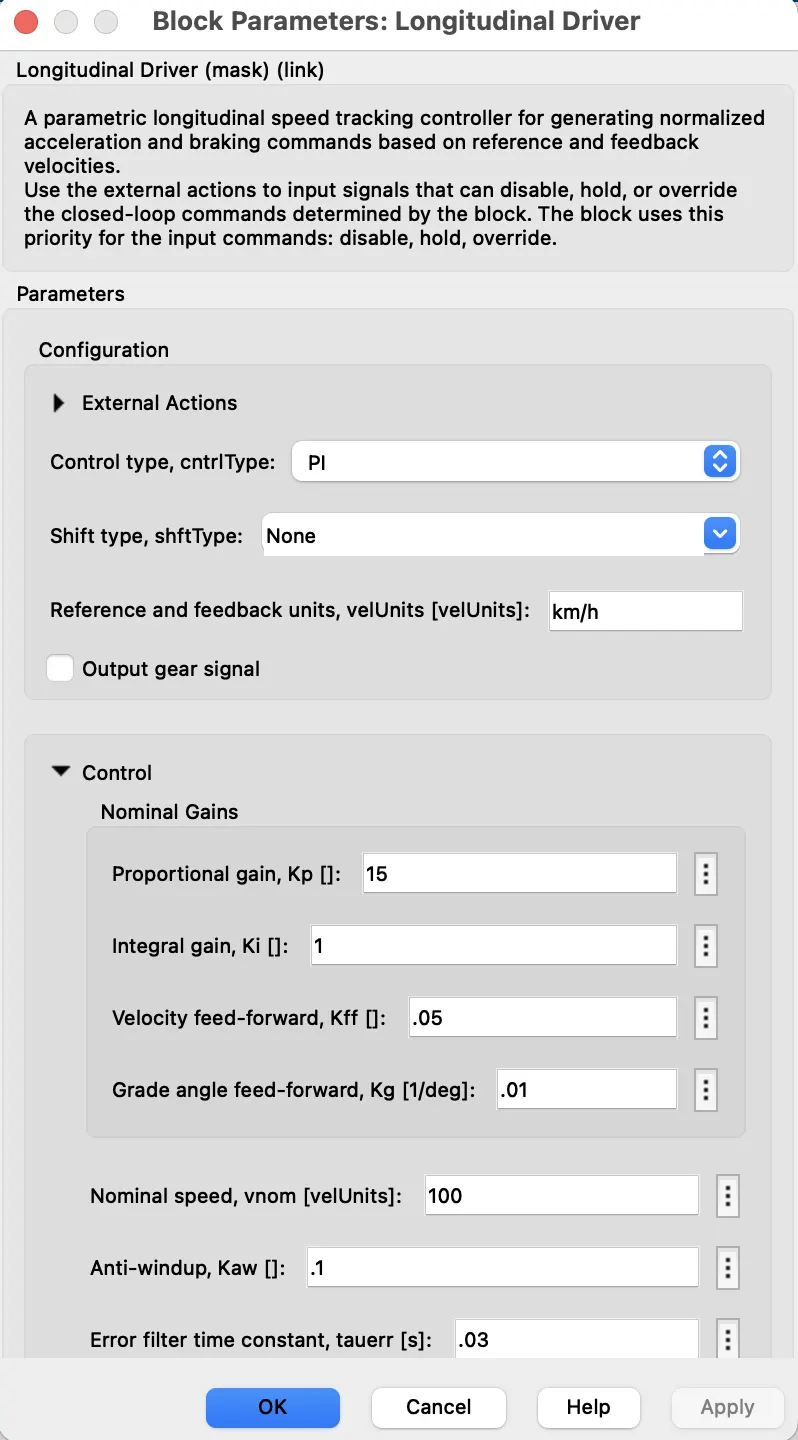
This block is used to create a longitudinal speed-tracking controller and it is based on reference and feedback velocities, the block generates normalized acceleration and braking commands that can vary from 0 through 1. We can use this block to model the dynamic response of a driver or to generate the commands necessary to track a longitudinal drive cycle.
The block parameters is as shown below,
Controller subsystem:
Controlled PWM Voltage source:
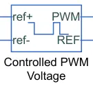
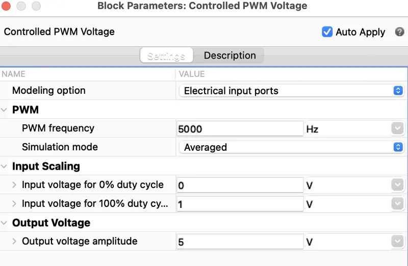
This block creates a Pulse-Width Modulated (PWM) voltage across the PWM and REF ports. The output voltage is zero when the pulse is low, and is equal to the Output voltage amplitude parameter when high. Duty cycle is set by the input value. Right-click the block and select Simscape->Block choices to switch between electrical +ref/-ref ports and PS input u to specify the input value.
At time zero, the pulse is initialized as high unless the duty cycle is set to zero or the Pulse delay time is greater than zero.
The Simulation mode can be set to PWM or Averaged. In PWM mode, the output is a PWM signal. In Averaged mode, the output is constant with value equal to the averaged PWM signal.
Select Simulation mode as Averaged.
Power Converter:
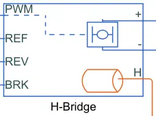
H-Bridge is used as a DC-DC converter:
 .
. 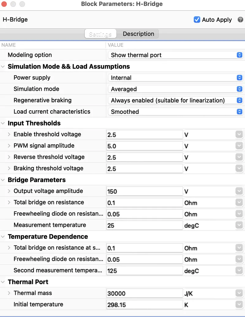
This block represents an H-bridge motor drive. The block can be driven by the Controlled PWM Voltage block in PWM or Averaged mode. In PWM mode, the motor is powered if the PWM port voltage is above the Enable threshold voltage. In Averaged mode, the PWM port voltage divided by the PWM signal amplitude parameter defines the ratio of the on-time to the PWM period.
Using this ratio and assumptions about the load, the block applies an average voltage to the load that achieves the correct average load current.
The Simulation mode parameter value must be the same for the Controlled PWM Voltage and H-Bridge blocks.
If the REV port voltage is greater than the Reverse threshold voltage, then the output voltage polarity is reversed. If the BRK port voltage is greater than the Braking threshold voltage, then the output terminals are short circuited via one bridge arm in series with the parallel combination of a second bridge arm and a freewheeling diode. Voltages at ports PWM, REV and BRK are defined relative to the REF port.
If exposing the power supply connections, the block only supports PWM mode.
Temperature Sensor:
Temperature Sensor is used to mesure the temperature of H-Bridge and Motor.
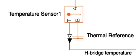
This block measures temperature in a thermal network. There is no heat flow through the sensor. The physical signal port T reports the temperature difference across the sensor.The measurement is positive when the temperature at port A is greater than the temperature at port B.
Solver Configuration:
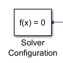
Defines solver settings to use for simulation.
Reference:
Electrical Reference:  Used to ground the all the electrical connections.
Mechanical Rotational Reference:  Used to ground all the mechanical rotational parts.
Thermal Reference: 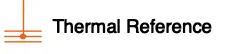 Used to ground the thermal sensor.
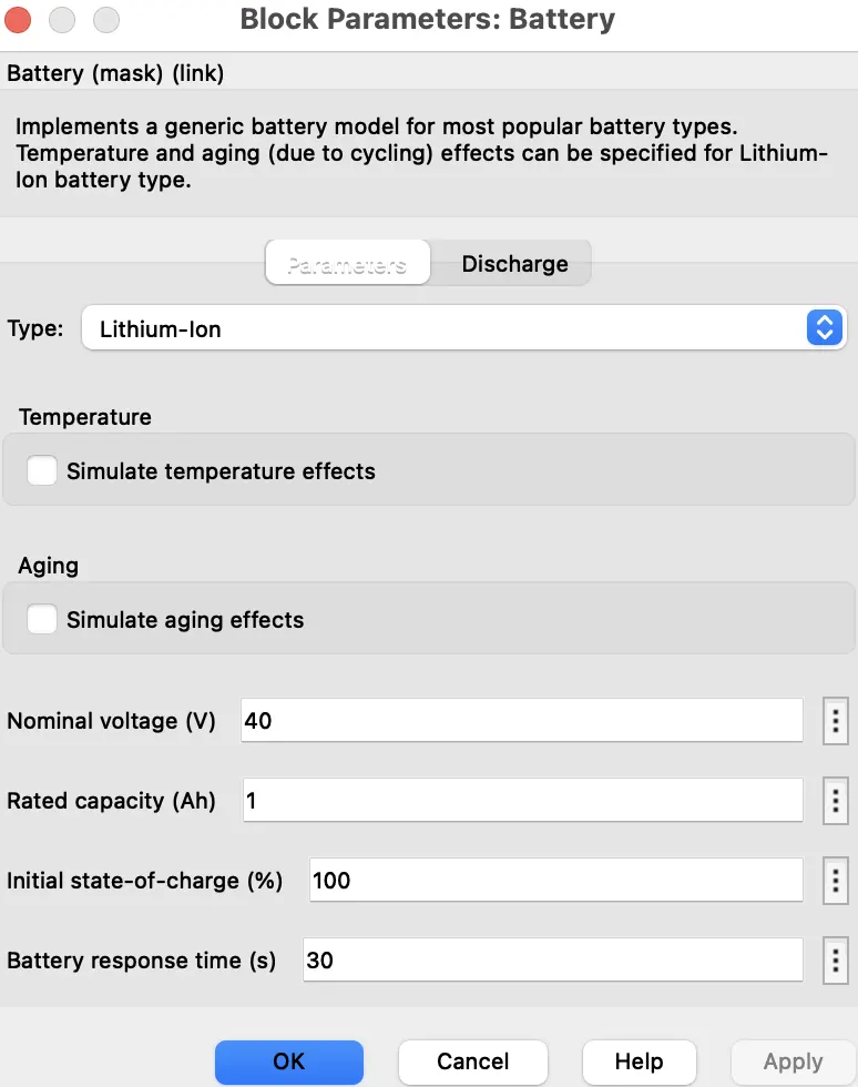
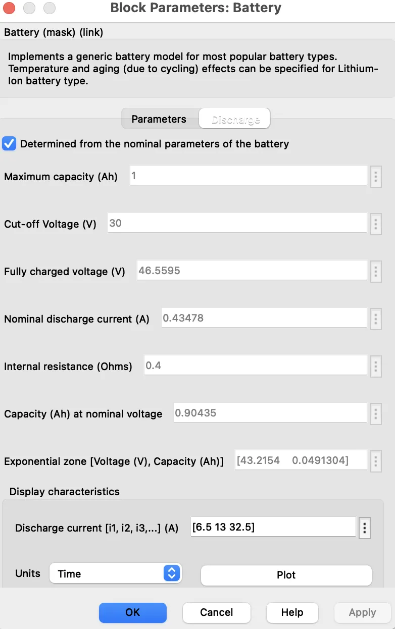
Battery Simulation:
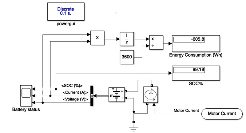
The battery is required to power the controller and motor. The controller uses the battery power according to produce the input given by the motor to obtain maximum speed.
The battery is also used to power every electrical component in the vehicle. The battery has two stage one is charging and another one is discharging state.
 .
.  .
.
SoC is the percentage or level of battery presents after certain travel or consumption of battery charge by the vehicle.
The majority of blocks are simscape blocks where physical to simulink converter is used to convert the physical signal from simscape block to simulink signal.
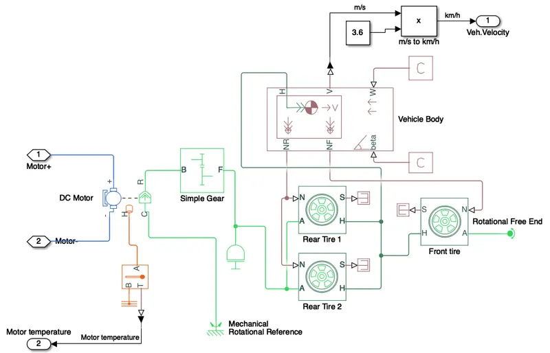
Motor & Vehicle Body & Transmission:
Motor will produce the rotational output which will give to the vehicle body and transmission system. The rotational output is taken by the gear system here to maintain the constant speed throughout the transmission without any loss in speed from the motor to tires.
Below is a diagram that is how it is how it inside the vehicle body and transmission system and in the main design, it is referred just only as a transmission system. Here is a Rear wheel drive transmission system.
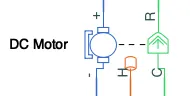
Motor type: DC Motor (PM brushed type motor)
Motor Parameters:
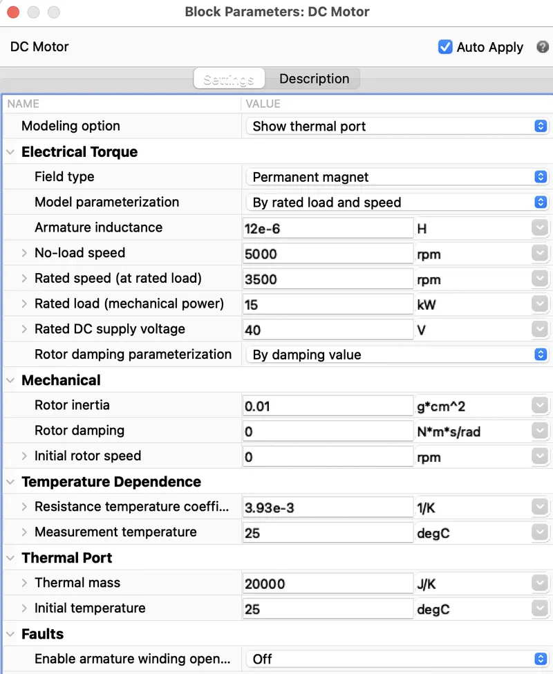
This block represents the electrical and torque characteristics of a DC motor includes Thermal port to sence the temperature of Motor.
The block assumes that no electromagnetic energy is lost, and hence the back-emf and torque constants have the same numerical value when in SI units. Motor parameters can either be specified directly, or derived from no-load speed and stall torque. If no information is available on armature inductance, this parameter can be set to some small non-zero value.
When a positive current flow from the electrical + to - ports, a positive torque acts from the mechanical C to R ports. Motor torque direction can be changed by altering the sign of the back-emf or torque constants.
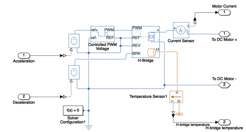
TheMotor controller will get input from the longitudinal driver. Its tasks are to control the speed of the motor and drive according to the input of the driver. Majorly motor controlled we designed had two main parts named PWM voltage generator and H-Bridge.
Input1 is getting from the accelmd of a longitudinal driver and it is given to a controlled voltage source block where it is input to the controlled PWM voltage. Controlled PWM voltage will generate a PWM signal in such a way that H-bridge will generate the required voltage to operate the DC motor for the given driver input. PWM voltage block negative reference and REF are grounded and REF of H-bridge respectively.
H-bridge is a motor controller that has IGBT components aligned in the shape of H and will operate only two at a time respectively to the input of the signal from the PWM block. When deceleration occur this H-bridge will give an output from the positive and negative terminals of it. These negative & positive terminals are later connected to the DC motor and battery. All these components are the simscape electrical components so they need a connection to the solver configuration block which helps to solve the simulation.
Simple gear box:
Represents a fixed-ratio gear or gear box. No inertia or compliance is modeled in this block. You can optionally include gear meshing and viscous bearing losses.
Connections B (base) and F (follower) are mechanical rotational conserving ports. Specify the relation between base and follower rotation directions with the Output shaft rotates parameter. Optionally include thermal effects and expose thermal conserving port H by right-clicking on the block and selecting Simscape block choices to switch between variants.
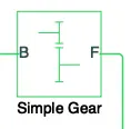
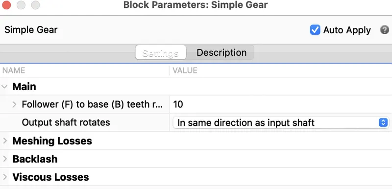
Output shaft rotates in in same direction of input shaft.Base is connected to the Motor shaft and the follower is connected to the Rear wheel derive.
Inertia:
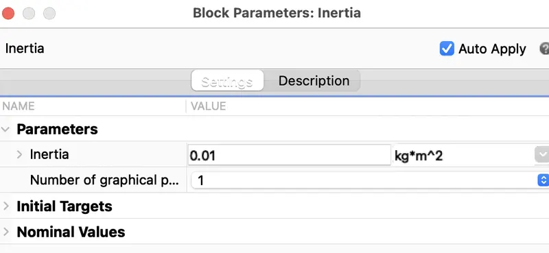
The block represents an ideal mechanical rotational inertia.
 .
.  .
.
The block has one mechanical rotational conserving port. The block positive direction is from its port to the reference point. This means that the inertia torque is positive if the inertia is accelerated in the positive direction.
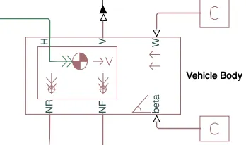
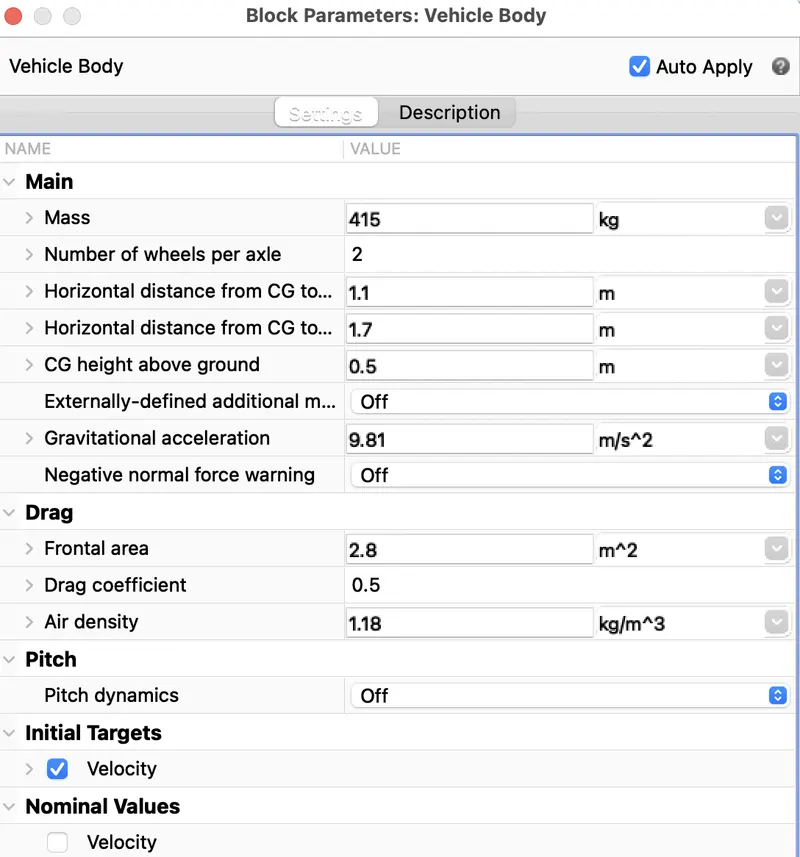
Vehicle Body:
Wheels:
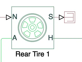
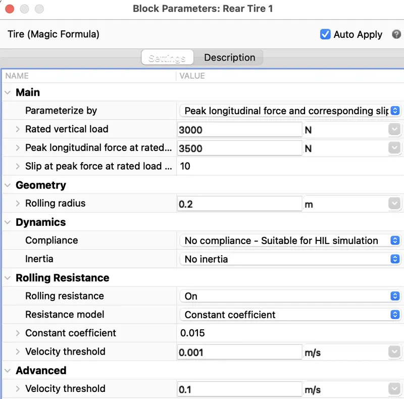
Represents the longitudinal behavior of a highway tire characterized by the tire Magic Formula. The block is built from Tire-Road Interaction (Magic Formula) and Simscape Foundation
Library Wheel and Axle blocks. Optionally, the effects of tire inertia, stiffness, and damping can be included.
Connection A is the mechanical rotational conserving port for the wheel axle. Connection H is the mechanical translational conserving port for the wheel hub through which the thrust developed by the tire is applied to the vehicle. Connection N is a physical signal input port that applies the normal force acting on the tire. The force is considered positive if it acts downwards. Connection S is a physical signal output port that reports the tire slip. Optionally expose physical signal port M by setting Parameterize by to Physical signal Magic Formula coefficients. Physical signal port M accepts a four element vector corresponding to the B, C, D, and E Magic Formula coefficients.
RESULTS:
1. IM240 Driving cycle:
Velocity:
Temparature:
Distance travelled:
Battery Status:
Battery SoC and Energy consumption:
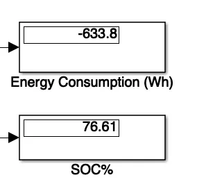
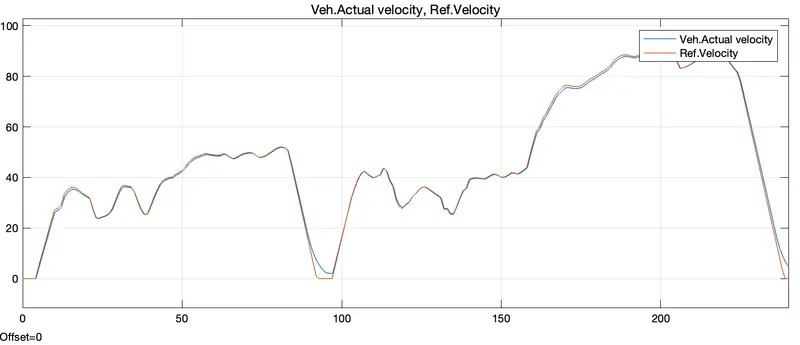
The actual Speed is approximately followed the 90% of reference Drive cycle.
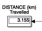
Distance travelled during 240sec is 3.155km
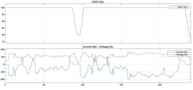
Energy consumed is -633.8Wh at the end of the cycle.
The SoC% of the battery is reduced to 76.61%
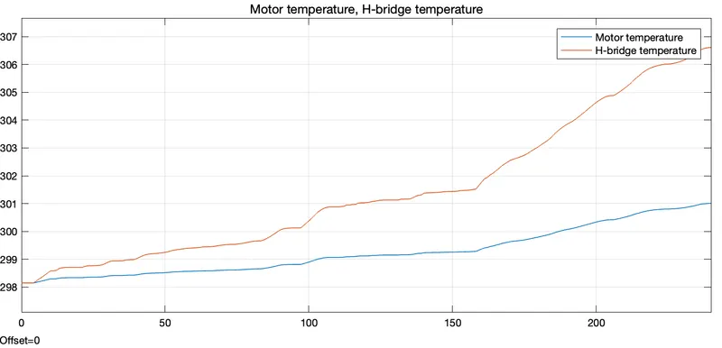
The Temperature of Motor is increased to 301K
The Temperature of Controller is ≈306.6K
2. WOT Driving cycle:
Velocity:
Temparature:
Distance travelled:

Battery Status:
Battery SoC and Energy consumption:
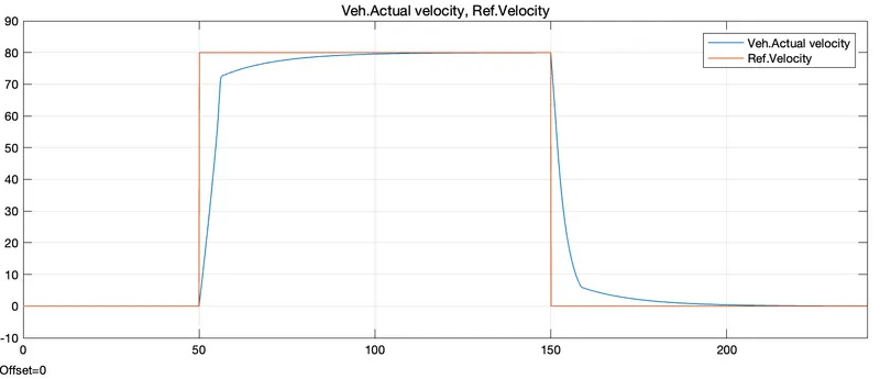
The actual Speed is approximately followed the 60-70% of reference Drive cycle.
Distance travelled during 100sec is 2.208km
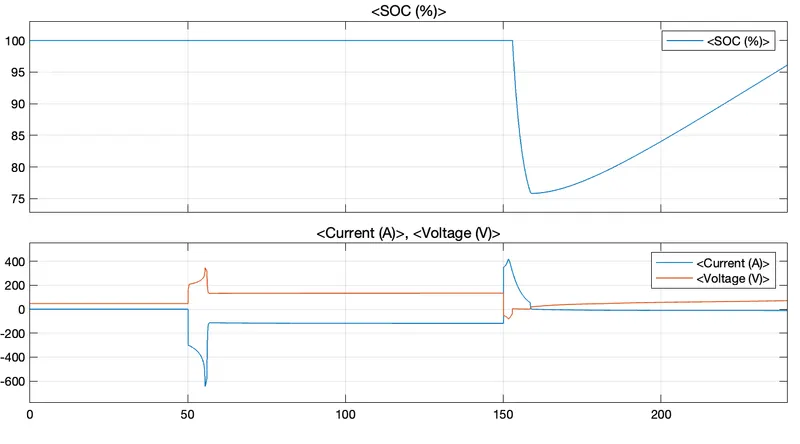
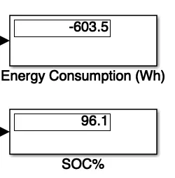
Energy consumed is -603.8Wh at the end of the cycle.
The SoC% of the battery is reduced to 96.1%
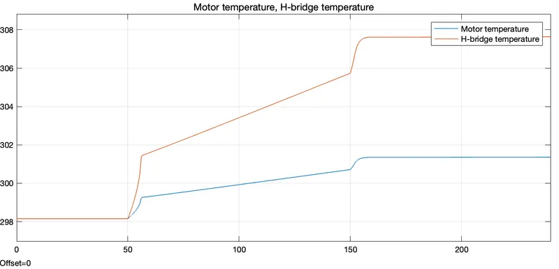
The Temperature of Motor is increased to ≈301.5K
The Temperature of Controller is ≈307.7K
3. User Driving cycle with 45kmph constant speed for 100km distance:
Velocity:
Temparature:
Distance travelled:
Battery Status:
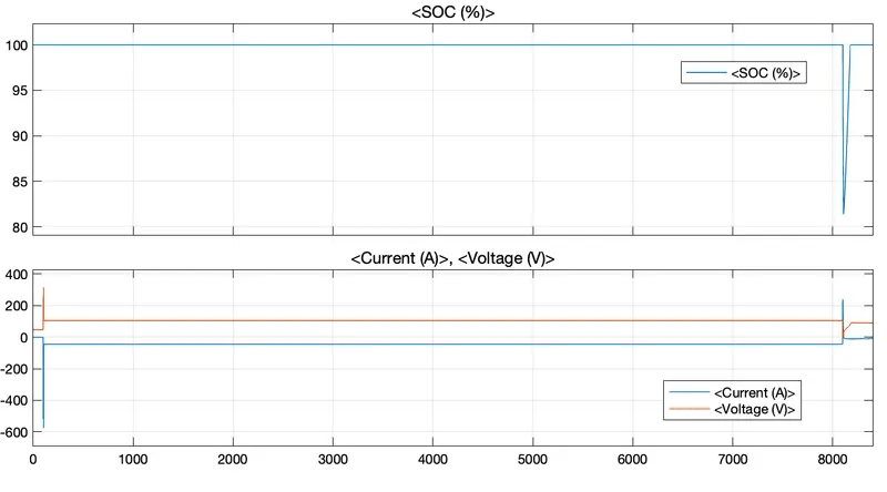
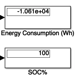
Battery SoC and Energy consumption:
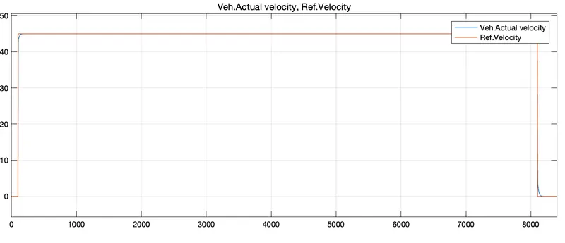
The actual Speed is approximately followed the 98% of reference Drive cycle.
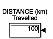
Distance travelled during 8000sec is 100km
Energy consumed is -10610Wh at the end of the cycle.
The SoC% of the battery is reduced to 100%
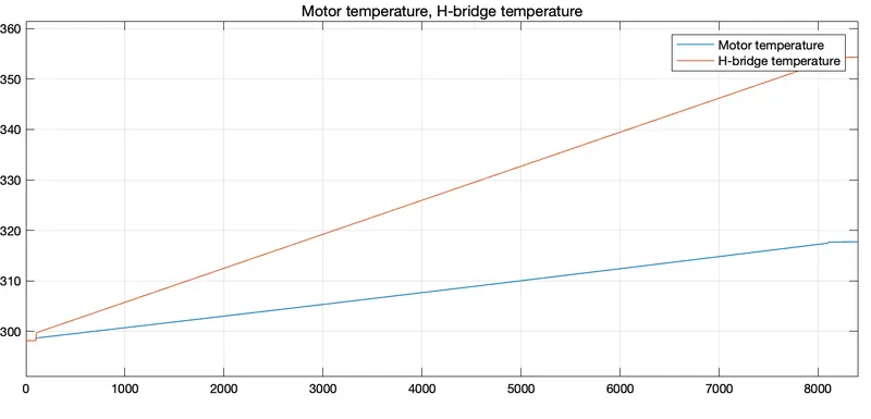
The Temperature of Motor is increased to ≈318K
The Temperature of Controller is ≈354K
Conclusion:
As per the Motor speciation, Type of controller, Vehicle Parameters & Battery used we could see that the reference speed almost matches with the vehicle for IM240 drive cycle, but it not matched when we need a very steep acceleration. Hence we have to further change the parameters of the system and try simulating to achieve the results.
The Parameters that can be changed / Improved:
1.Optimization of Battery pack for increased mileage and peak performance
2.Optimization in the vehicle parameters such as vehicle mass, Front Area, Drag, Tire design etc
3.Better Motor characteristics or Motor such as BLDC motor, which reduces the losses produced from brushes and better efficiency. Hence Better motor power and Torque can be achieved
4.Use of actual PID Controller system rather than basic PWM signal generator block. This enables us to tune the system accordingly and brings down the error.
5.Provide better cooling arrangement to avoid losses.