Week 4.1: Project Steady state simulation of flow over a throttle body
OBJECTIVE : To simulate flow through throttle valve inside elbow for steady state condition and investigate flow properties .
INTRODUCTION :
Flow through elbow and tube with valve (Throttle) inside is very basic problem for Computation fluid dynamics and are interest of everyday life use.
A butterfly valve is from a family of valves called quarter-turn valves. In operation, the valve is fully open or closed when the disc is rotated a quarter turn. The "butterfly" is a metal disc mounted on a rod. When the valve is closed, the disc is turned so that it completely blocks off the passageway.
Butterfly valves are generally favored because they cost less than other valve designs, and are lighter weight so they need less support. The disc is positioned in the center of the pipe. A rod passes through the disc to an actuator on the outside of the valve. Rotating the Actuator turns the disc either parallel or perpendicular to the flow.
PROCEDURE :
- Creation of geometry
- Drop the file available to us since avallaible body contains thickness of pipe which need to remove ,select angle method and click on outer part of body once outer part (shell) selected delete the shell .
- same way delete both side (inlet , outlet ) flange
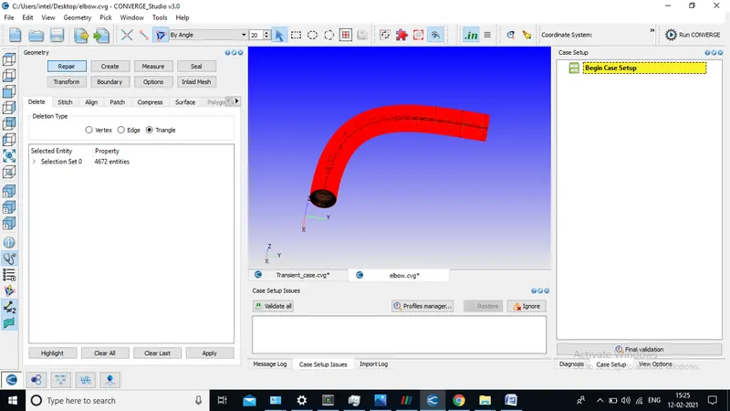
- scale geometry to 0.001 since geometry available was in meter .
- Check for normal orientation
- run the diagnosis for checking further geometry errors.
2. Selection of material :
-
- Check on gas simulation & Reaction .
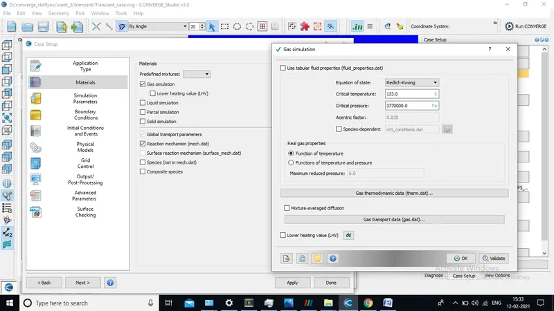
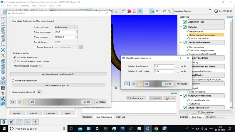
- Add species O2 ,N2
3 . Assign solving parameter
- Select steady state solver , Full hydrodynamic and compressible flow
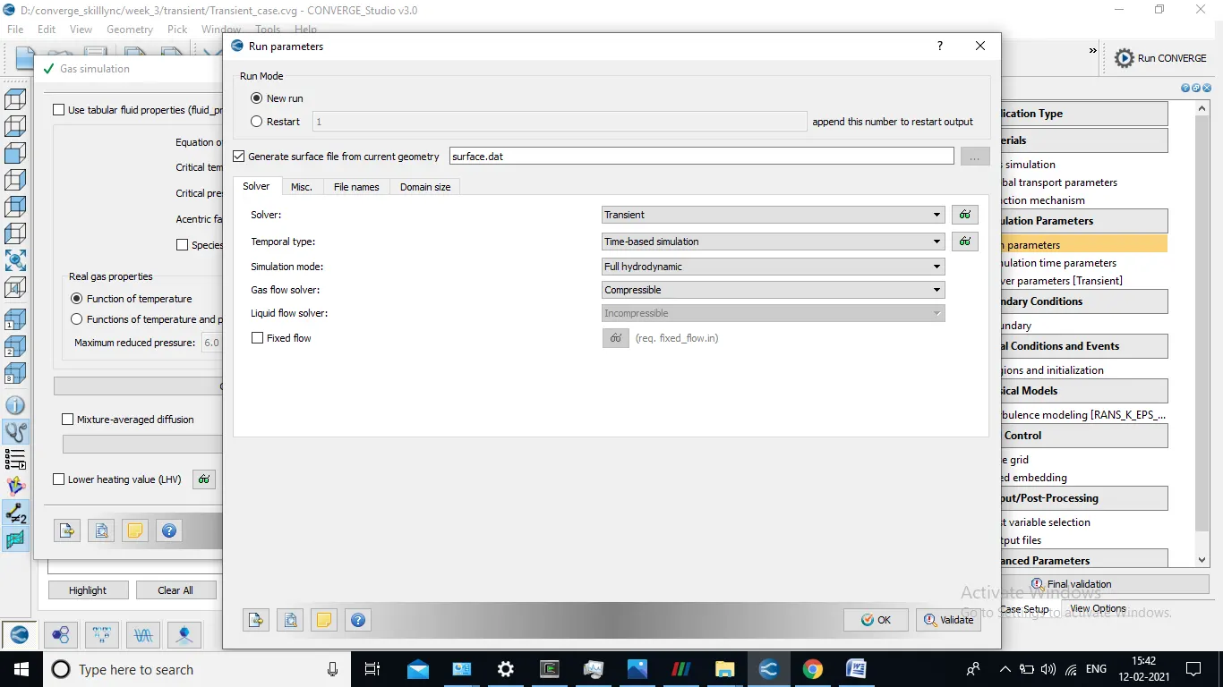
- In misc. uncheck used share memory and check monitor steady state
- In simulation time parameter provide values according to simulation
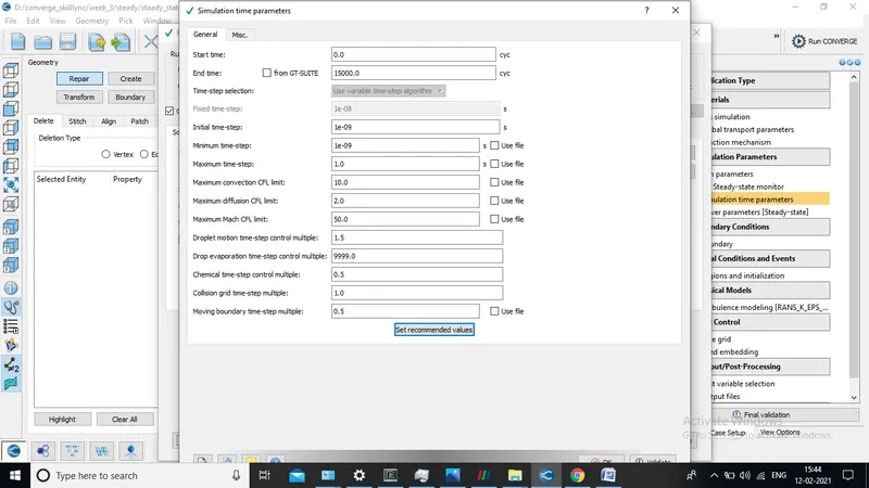
- Solver scheme select PISO solver keep other things same .
4. Assign Boundary at face and give bounadry condition.
- Select Angle method and select on faces ( I,e inlet ) and click on boundary and add boundry follow same procedure for others faces ( ELBOW , OUTLET )
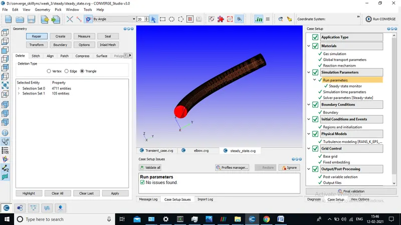
- For select Throttle body outer elbow select box and drag the on the outer elbow and hide selection once throttle appears gives boundary flag.
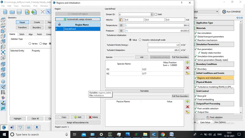
- Once give boundary condition create region & Name and give same region name to all boundaries that we have created
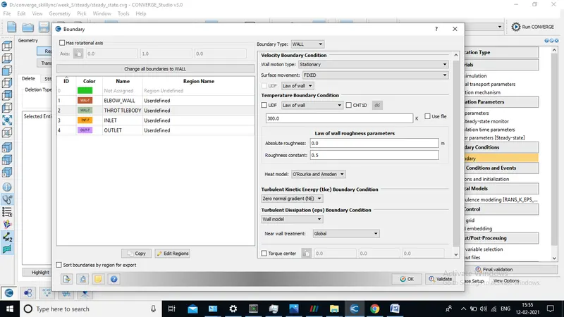
Elbow wall bounday condition
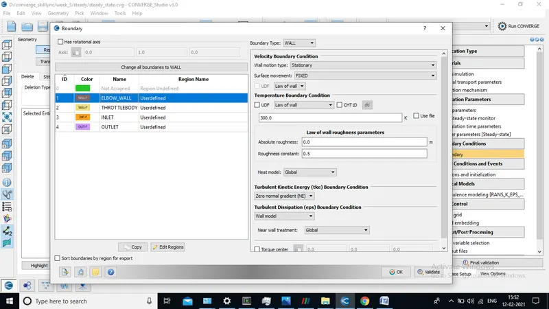
Throttle wall bounday condition
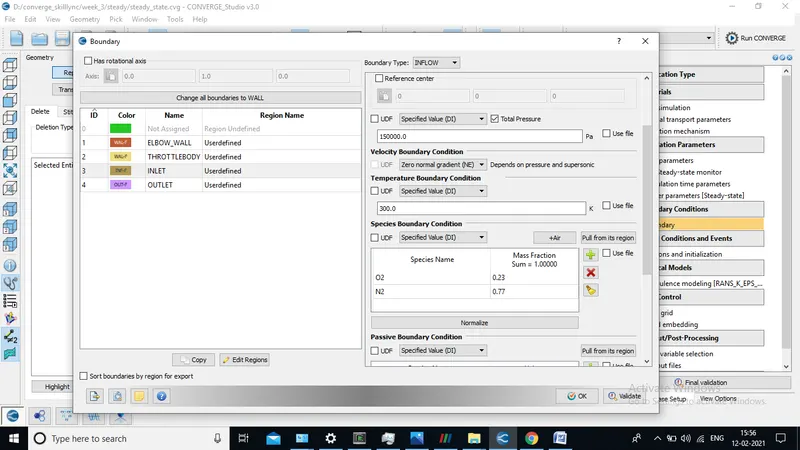
Inlet bounday condition
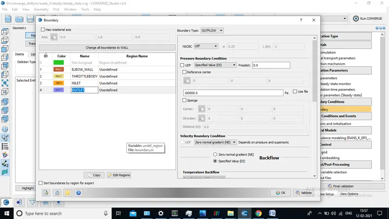
Outlet wall bounday condition
1). Inlet
- Boundary type : INFLOW
- Pressure : 150000 pa
- Temp :300 K
- Velocity :Zero Gradient
2).outlet
- Boundary type : OUTFLOW
- Pressure : 100000 pa
- Temp :300 K
- Velocity :Zero Normal Gradient
3). Elbow wall
- Boundary type : WALL
- Wall motion : Stationary
- Surface movement : Fixed & Law of wall ( Turbulence is present near throttle body & elbow )
- Turbulent kinetic energy boundary condition : Zero Normal Gradient
- Turbulent Dissipation Boundary condition : Wall Model
4). Throttle wall
- Boundary type : WALL
- Wall motion : Stationary
- Surface movement : Fixed & Law of wall ( Turbulence is present near throttle body & elbow )
- Turbulent kinetic energy boundary condition : Zero Normal Gradient
- Turbulent Dissipation Boundary condition : Wall Model
5 .Meshing generation
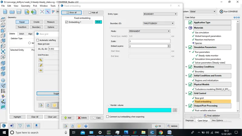
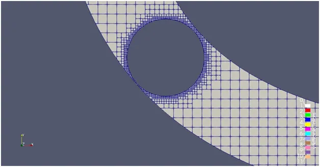
- Provide appropriate valued of mesh size as shown in figure
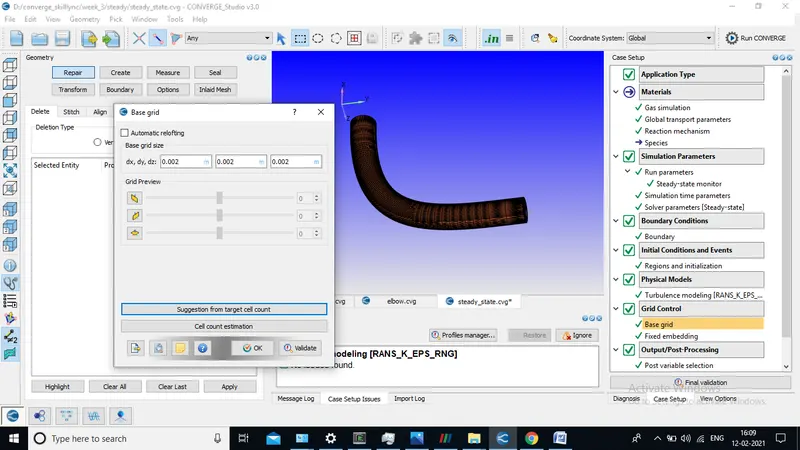
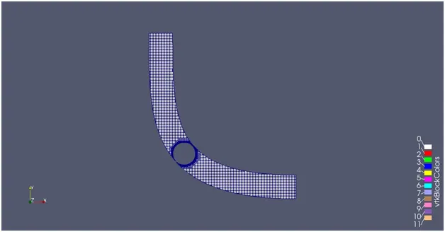
- Meshing Close to Throttle body must be fine enough for accurate result hence fixed embedding is select with proper no. of layer
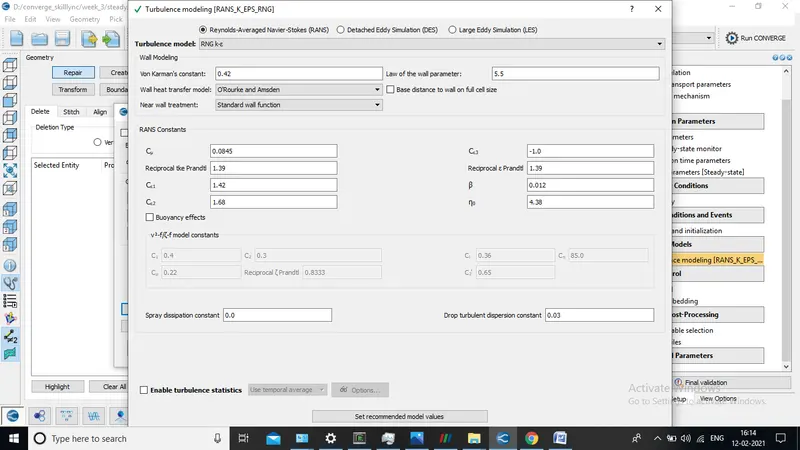
6). Selection of Turbulence Modelling
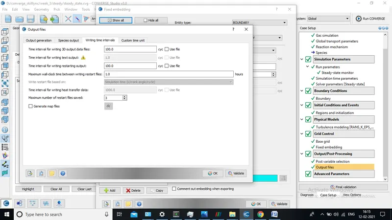
7. Output post processing data
- Select the variable those which needs to post process.
- Provide Data for writing time interval according to simuation
RESULT
Meshing Configuration
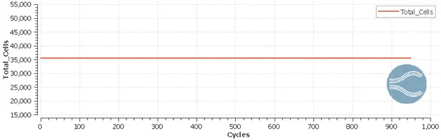
1). Cell count plot
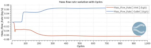
2).Mass flow rate plot at inlet & outlet
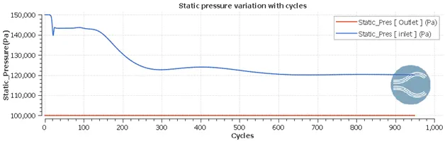
3).Total pressure plot at inlet & outlet
4).Velocity plot at inlet & outlet
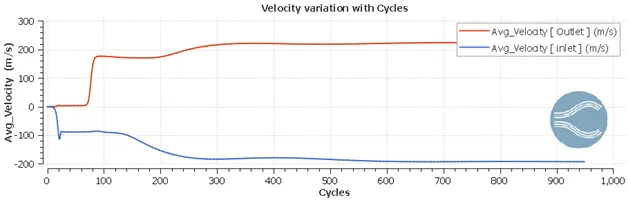
- Outlet velocity converges at near about 197 m/s , from plot plot it can be shown that momentum conservation follow for our case
5 ).Velocity countour
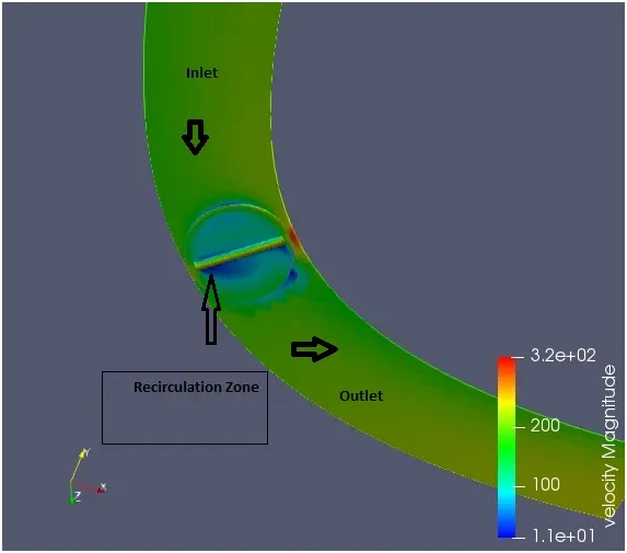
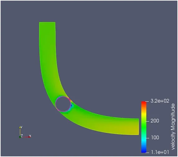
- Here from above counter in the back part of throttle body due to low velocity & adverse pressure gradient recirculation zone occures
- On the side of throttle valve velocity is higher that is becuase of same mass conservation velocity must be high since side area of throttle is very low
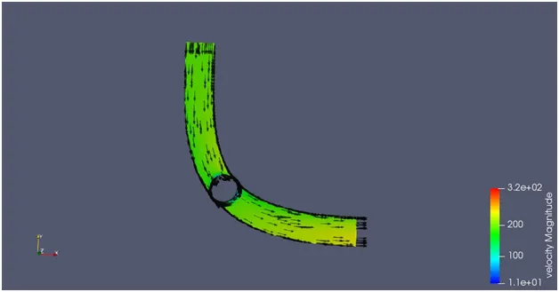
- Max. velocity is found as 320 m/s ( Red Region ) & at outlet velocity comes as approx. 200 m/s
5). Pressure contour
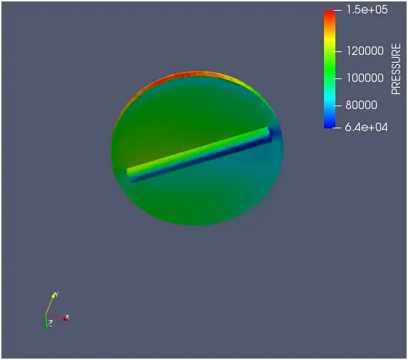
- Here in pressure contour max. pressure observe at leading edge of throttle valve ( Top red region) becuase of restriction in flow path fluid exerted more pressure while on the back part of throttle body pressure seems to have low (Blue Region ).
5 ).Velocity Vector
5 ).Velocity Stremline plot
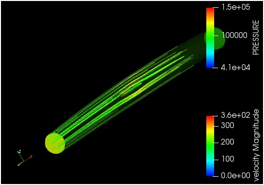
- Velocity Stemline found as symmetric because of no movement in throttle body.
CONCLUSION
- LOCATION OF MAX. VELOCITY & PRESSURE AND RECIRCULATION ZONE CAN BE INTENFIED WITH HELP OF THIS SIMULATION
- VARIOUS PLOTS FOR PRESSURE , MASS FLOW RATE AND VELOCITY ENSURES THAT MOMENTUM CONSERVATION LAW FOLLOWS HERE
- FLOW OVER THROTTLE BODY IS SUCCESSFULLY CONDUCTED WITH PROPER SETUP FOR STEADY STATE CONDITION IN CONVERGE C.F.D