Challenge on Combustion
OBJECTIVE: To Perform a combustion simulation on the combustor model and plot the variation of the mass fraction of the different species CO2, H2O, CH4, N2, O2, NOx emissions & Soot formation and further add water content in fuel and investigate emission & Soot formation and variation in outlet temperature of burner.
TYPE OF COMBUSTION BASED ON MIXING :
1). Non-Premixed Combustion
The fuel and air are not mixed before entering the combustion chamber and enters as two different streams. In non-premixed combustion, fuel and oxidizer enter the reaction zone in distinct streams Example of such combustion can be found in diesel engines, direct injection, etc.
2) Pre-Mixed Combustion
The fuel and air are mixed before entering the combustion chamber. Example of such combustion is the carburetor . in premixed systems, in which reactants are mixed at the molecular level before burning.
3) Partially Pre-Mixed Combustion
The fuel and air are partially mixed before entering the combustion chamber. Example of such combustion is IC engine used in the automobile.
- A common way to characterize non-premixed flames is to look at the relative importance of the mixing and reaction processes. This type of comparison is frequently done in reactive systems by using dimensionless ratios. In the case of non-premixed flames, the Damkolher Number is used to compare the timescale of mixing to the timescale of chemical reaction.
- When the Damkohler number is very large, the reaction occurs in a very thin region between the fuel and oxidizer and the flame speed is limited by the diffusion rate
- This is the basis for the Flame-Sheet model for diffusion flames When the Damkohler number is very small.
SOOT FORMATION PHENOMENON
Soot forms as a result of incomplete combustion. To achieve incomplete combustion instead of complete combustion, the fuel must burn at a lower temperature with a slightly reduced supply of oxygen. When the fuel burns, it breaks into small particles that include soot, which settles out as a dark powdery deposit.
Soot is a carbonaceous particulate matter produced in pyrolysis and combustion when conditions are such to allow gas-phase molecular growth reactions of the fuel hydrocarbon and its decomposition products to compete with further decomposition and oxidation reactions.
A common way to characterize non-premixed flames is to look at the relative importance of the mixing and reaction processes. This type of comparison is frequently done in reactive systems by using dimensionless ratios. In the case of non-premixed flames, the Damkohler number () is used to compare the timescale of mixing to the timescale of chemical reaction.
When the Damkohler number is very large (), the reaction occurs in a very thin region between the fuel and oxidizer and the flame speed is limited by the diffusion rate (e.g., the diffusion flame above). This is the basis for the Flame-Sheet model for diffusion flames When the Damkohler number is very small (), a premixed flame occurs as mixing is fast relative to reaction. If the timescale of mixing and reaction are similar () a Partially-Premixed flame occurs where both the mixing and reaction processes are important to consider.
DIFFERENT COMBUSTION MODEL IN ANSYS
Nox , Sox And Soot Pollutant Model
Pollutant Formation Model Pollutant species, such as NOx, SOx or soot, typically can be calculated by post-processing a combusting flow solution. ANSYS offers several pathways to predict NOx formation in gas, oil and coal flames using thermal, fuel and prompt NOx mechanisms and to predict NOx reduction via re-burning or selective non-catalytic reduction (SNCR). One- and two-step soot models are available; soot radiation can be included in the simulation.
Eddy Dissipation Model
Fast Chemistry The eddy dissipation model (EDM), in combination with the finite rate chemistry model, allows accurate simulation of the heat release and the distribution of the main chemical species for many industrial applications, such as gas turbines, internal combustion engines, furnaces and thrusters. The EDM can be used for all types of combustion as well as in combination with advanced scale-resolving turbulence and multiphase models.
PROCEDURE :
Mainly following four parts included.
1). Pre-procesing
2). Meshing.
3). Solving .
1) . Pre-prerocessing :
- It's include preparation of geometry which is being use in our simulation part .
- Load the step file which is available to spaceclaim .
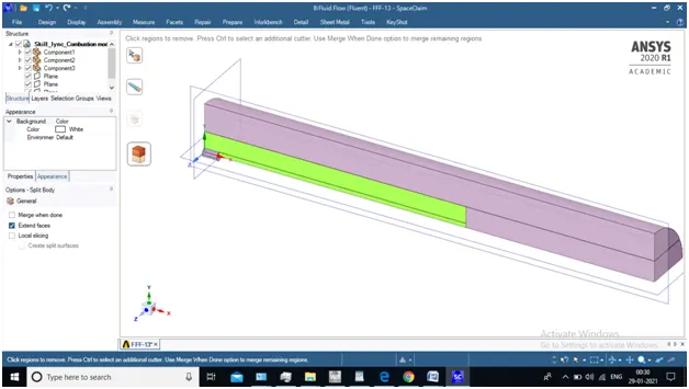
- Select plane and click on split body remove half body (symmetric) as shown in figure
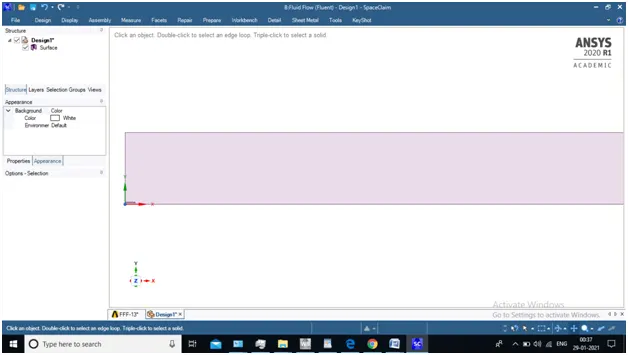
- Combine geometry and copy face and paste it to another file geometry is ready for meshing
2) . Meshing :
- Mesh need to refined where mixing is occured and place where combustion starts for better accuracy and capturing physics.
- Method : All triangular method (5 mm )
- Edge sizing method is used with different devision for different edge ( air inlet , fuel inlet etc)
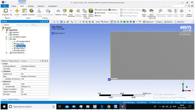
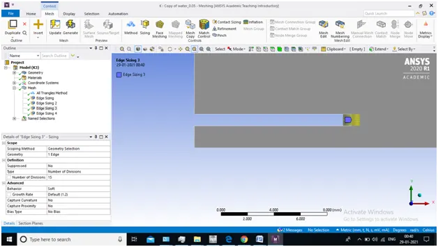
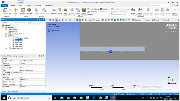
- Create Name selection At different Location (Edge)
3). solving :
- Solver Type : Pressure based type & Steady state
- 2D Space : Axysymmetric
- Viscous Model : K-epsilon Turbulence Model
- Species Model : Non premixed combustion
- Select right air -fuel mixture
- check mark volumetric reaction
- enable Eddy Dissipation in chemistry interaction
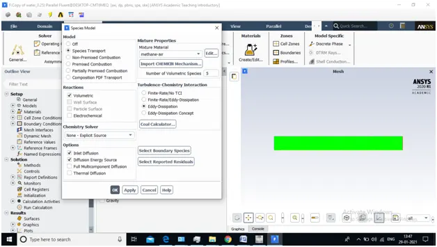
- Enable NOx model --> Prompt and Thermal (NOx) model
- Select No. Fuel stream and select Fuel
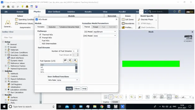
- Enable Soot Modeling ----> One step soot model
- Select the Fuel & Oxidant according to simulation
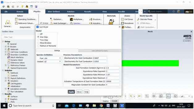
BOUNDARY CONDITION
1). Air inlet :
- Velocity magnitude : 0.5 m/s
- Temp : 300k
- Species Mass Fraction : O2 --> 0.23 % by mass Fraction
2). Fuel inlet :
- Velocity magnitude : 80 m/s
- Temp : 300k
- Species Mass Fraction : CH4 --> 0.95 % & H2O --> 0.05 by mass Fraction (According to simulation )
3) Wall
- No slip & Stationary Wall
4) Outlet
- Pressure Gauge : Zero Pascal
- Temp : 300K
- Initialize as Hybrid Solution and hit on calculation button.
4). Post - Processing :
- Plot the variation of different species at different location
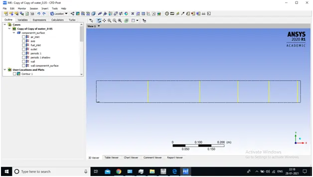
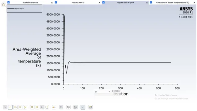
- Report the file of NOx & Soot Pollutant No. & Temp at outlet from Defination
- Create contour of Temp and create Animation
DIFFERENT CASES :
- Fuel Fraction (CH4) : 0.95 & Water (H2O) : 0.05
- Fuel Fraction (CH4) : 0.9 & Water (H2O) : 0.1
- Fuel Fraction (CH4) : 0.8 & Water (H2O) : 0.2
- Fuel Fraction (CH4) : 0.7 & Water (H2O) : 0.3
- Fuel Fraction (CH4) : 0.95 & Water Fraction (H2O) :0.05
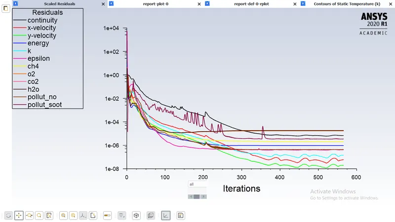
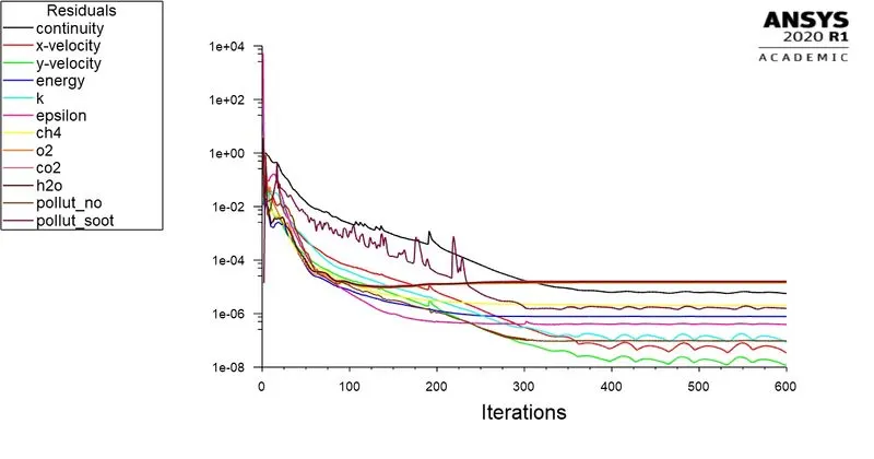
- RESIDUAL PLOT
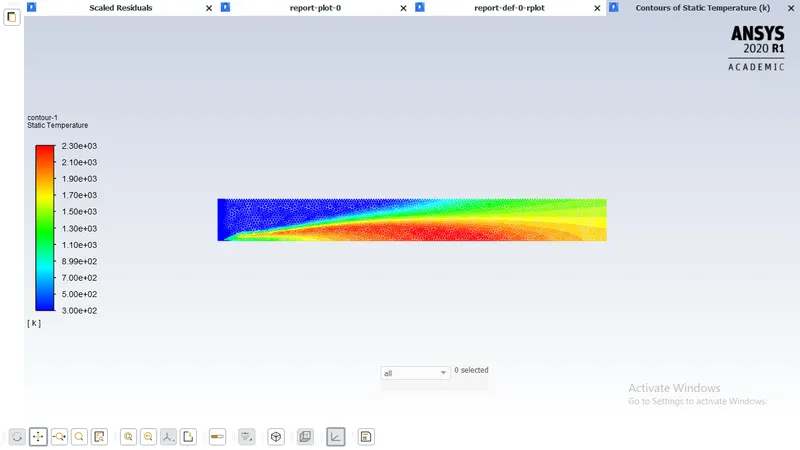
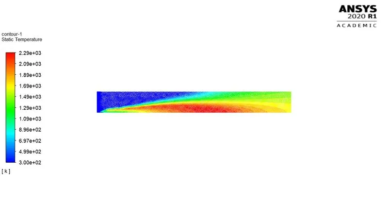
- TEMP. CONTOUR AT OUTLET
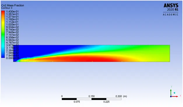
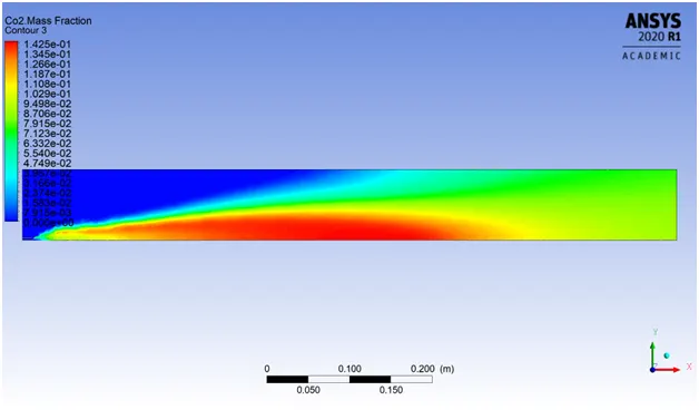
- CO2 MASS FRACTION CONTOUR
- CH4 MASS FRACTION CONTOUR
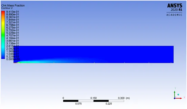
- NO MASS FRACTION CONTOUR
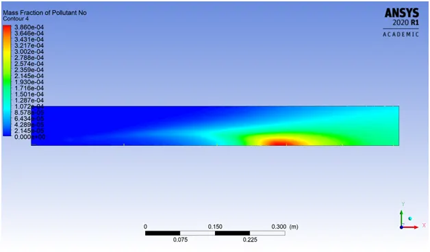
- SOOT MASS FRACTION CONTOUR
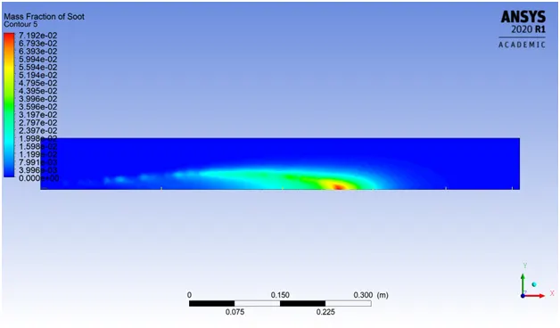
- H2O MASS FRACTION CONTOUR
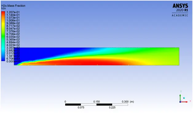
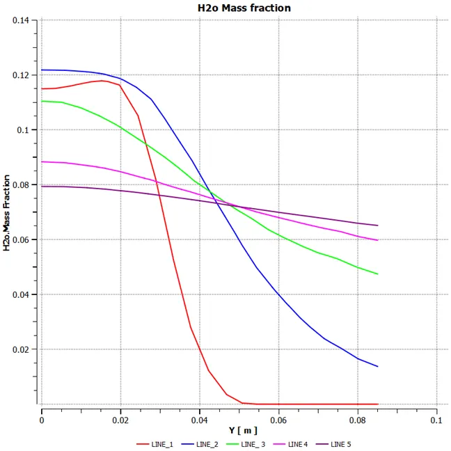
- H2O MASS FRACTION VARIATION AT DIFFERENT LINE PROBE
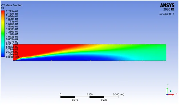
- O2 MASS FRACTION CONTOUR
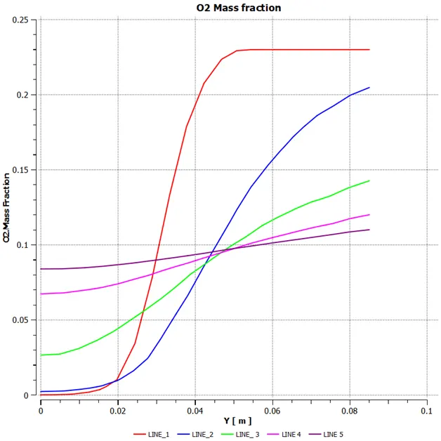
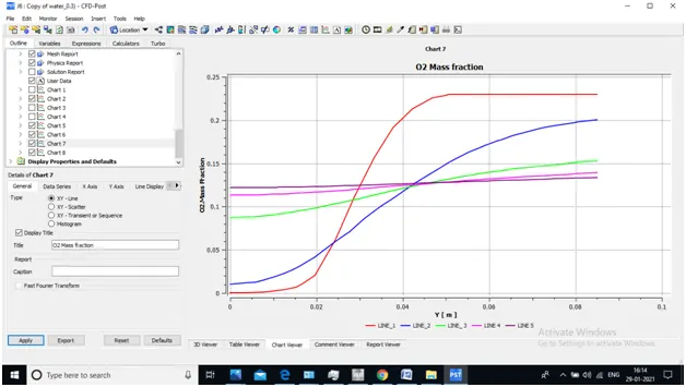
- O2 MASS FRACTION VARIATION AT DIFFERENT LINE PROBE
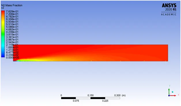
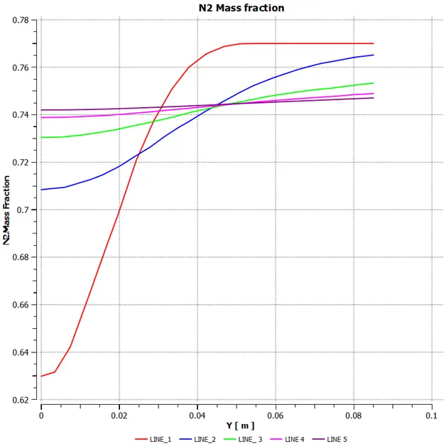
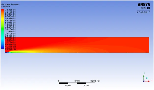
- N2 MASS FRACTION CONTOUR
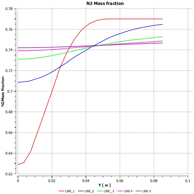
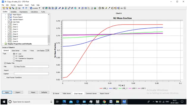
- N2 MASS FRACTION VARIATION AT DIFFERENT LINE PROBE
- Fuel Fraction (CH4) : 0.9 & Water Fraction (H2O) :0.1
- RESIDUAL PLOT
- TEMP. CONTOUR AT OUTLET
- CO2 MASS FRACTION CONTOUR
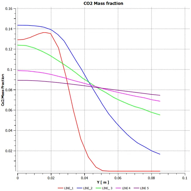
- CO2 MASS FRACTION VARIATION AT DIFFERENT LINE PROBE
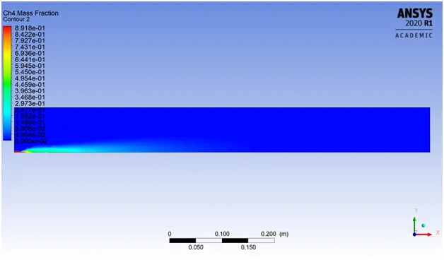
- CH4 MASS FRACTION CONTOUR
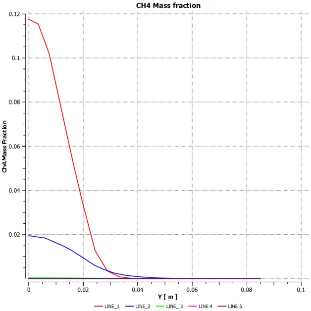
- CH4 MASS FRACTION VARIATION AT DIFFERENT LINE PROBE
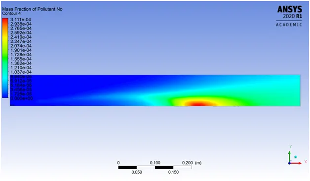
- NO MASS FRACTION CONTOUR
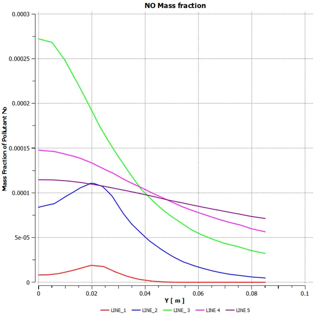
- NO MASS FRACTION VARIATION AT DIFFERENT LINE PROBE
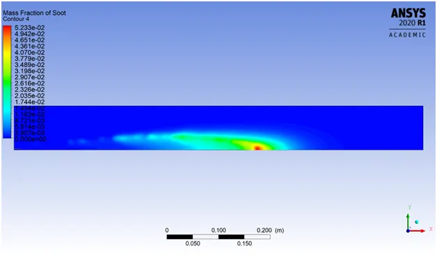
- SOOT MASS FRACTION CONTOUR
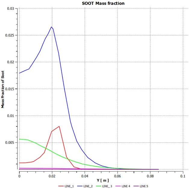
- SOOT MASS FRACTION VARIATION AT DIFFERENT LINE PROBE
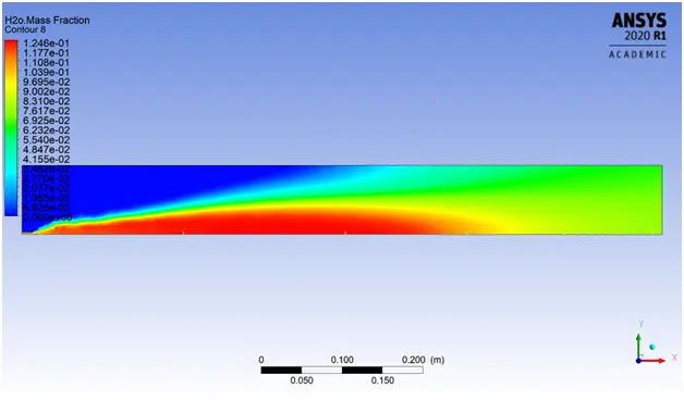
- H2O MASS FRACTION CONTOUR
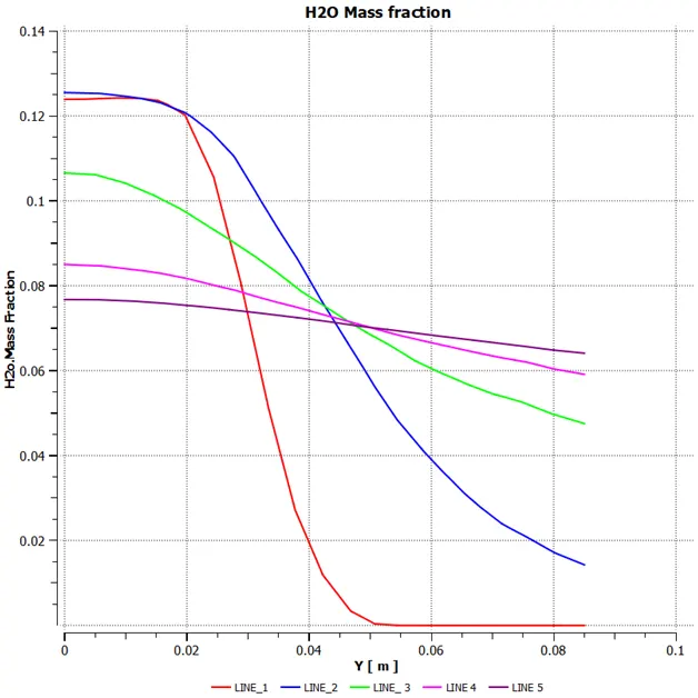
- H2O MASS FRACTION VARIATION AT DIFFERENT LINE PROBE
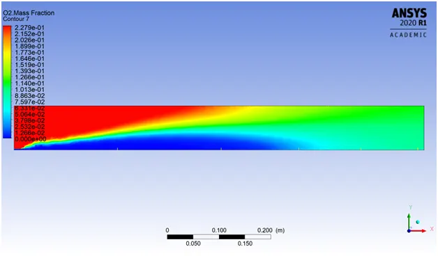
- O2 MASS FRACTION CONTOUR
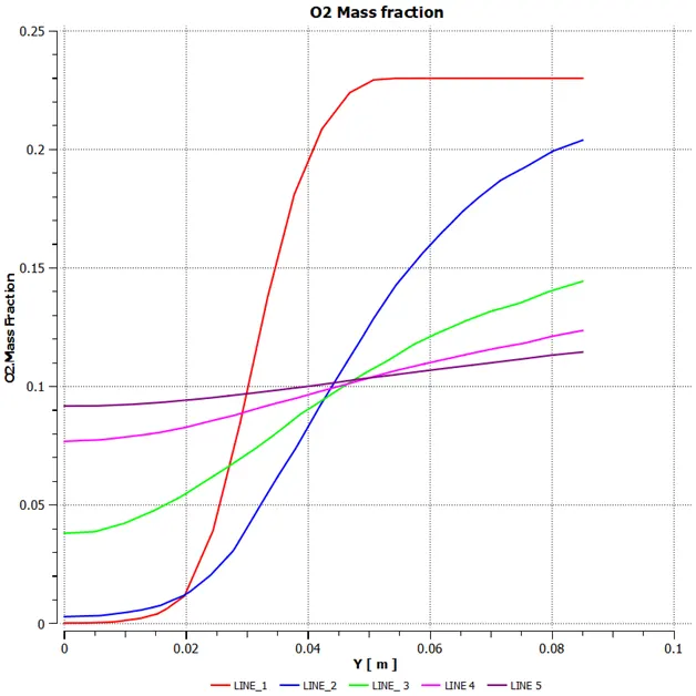
- O2 MASS FRACTION VARIATION AT DIFFERENT LINE PROBE
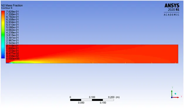
- N2 MASS FRACTION CONTOUR
- N2 MASS FRACTION VARIATION AT DIFFERENT LINE PROBE
- Fuel Fraction (CH4) : 0.8 & Water Fraction (H2O) :0.2
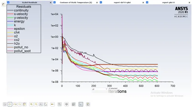
- RESIDUAL PLOT
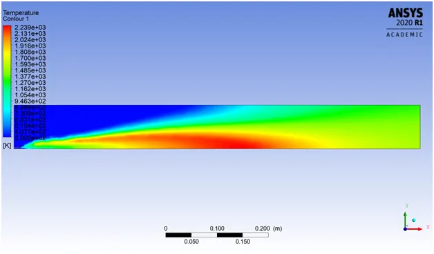
- TEMP. CONTOUR AT OUTLET
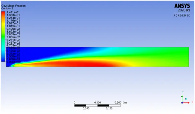
- CO2 MASS FRACTION CONTOUR
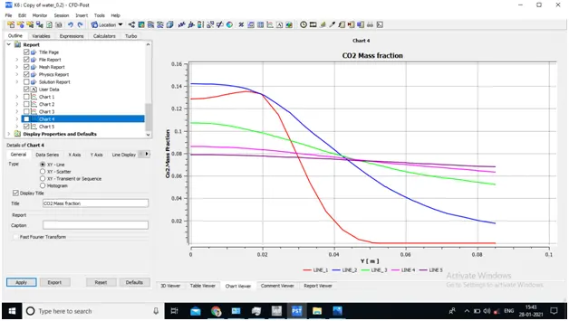
- CO2 MASS FRACTION VARIATION AT DIFFERENT LINE PROBE
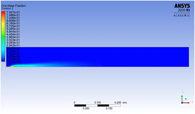
- CH4 MASS FRACTION CONTOUR
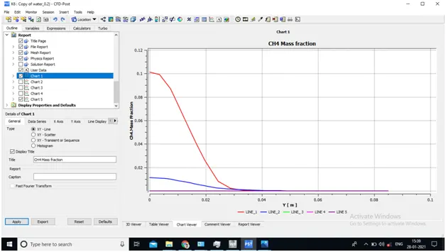
- CH4 MASS FRACTION VARIATION AT DIFFERENT LINE PROBE
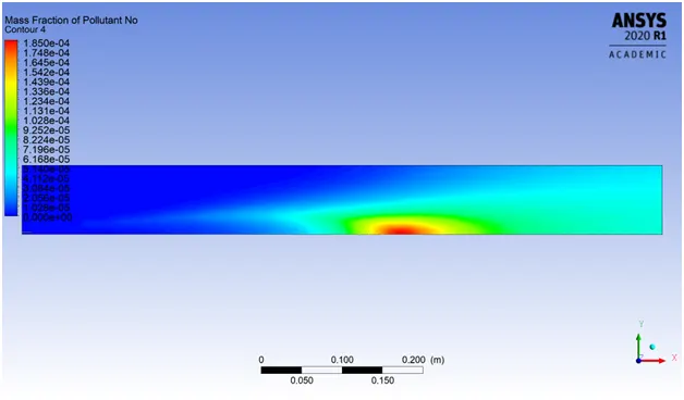
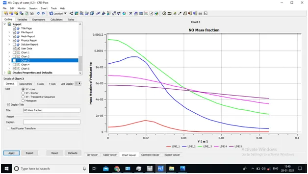
- NO MASS FRACTION CONTOUR
- NO MASS FRACTION VARIATION AT DIFFERENT LINE PROBE
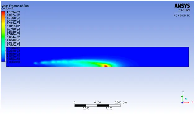
- SOOT MASS FRACTION CONTOUR
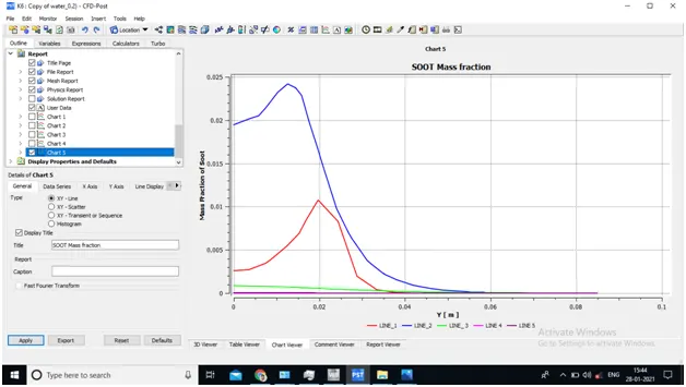
- SOOT MASS FRACTION VARIATION AT DIFFERENT LINE PROBE
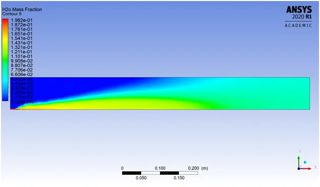
- H2O MASS FRACTION CONTOUR
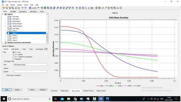
- H2O MASS FRACTION VARIATION AT DIFFERENT LINE PROBE
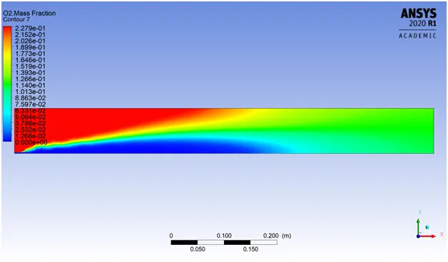
- O2 MASS FRACTION CONTOUR
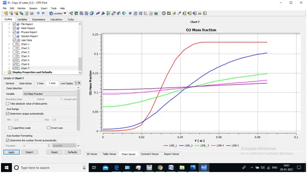
- O2 MASS FRACTION VARIATION AT DIFFERENT LINE PROBE
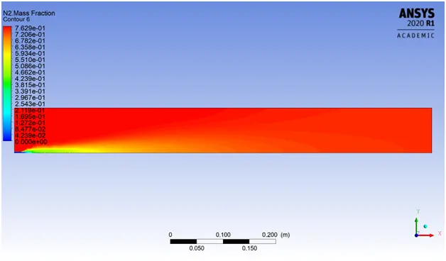
- N2 MASS FRACTION CONTOUR
- N2 MASS FRACTION VARIATION AT DIFFERENT LINE PROBE
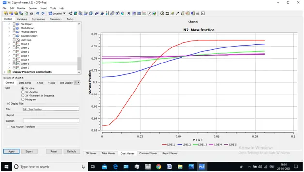
- Fuel Fraction (CH4) : 0.7 & Water Fraction (H2O) :0.3
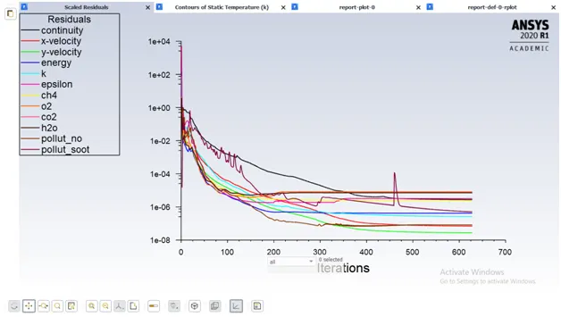
- RESIDUAL PLOT
- TEMP. CONTOUR AT OUTLET

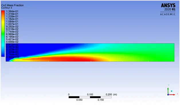
- CO2 MASS FRACTION CONTOUR
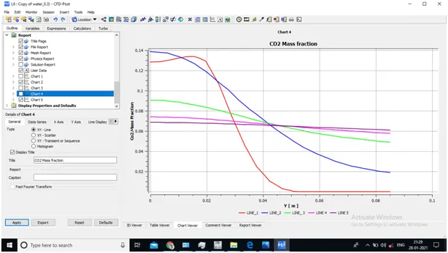
- CO2 MASS FRACTION VARIATION AT DIFFERENT LINE PROBE
- CH4 MASS FRACTION CONTOUR
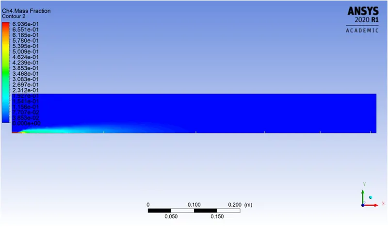
- CH4 MASS FRACTION VARIATION AT DIFFERENT LINE PROBE
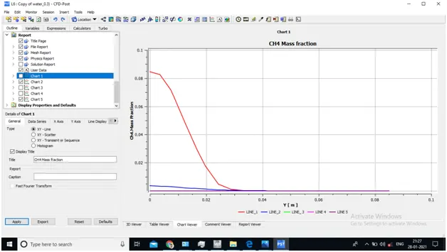
- NO MASS FRACTION CONTOUR
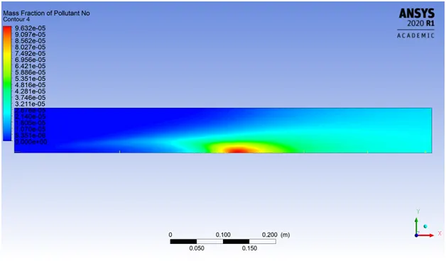
- NO MASS FRACTION VARIATION AT DIFFERENT LINE PROBE

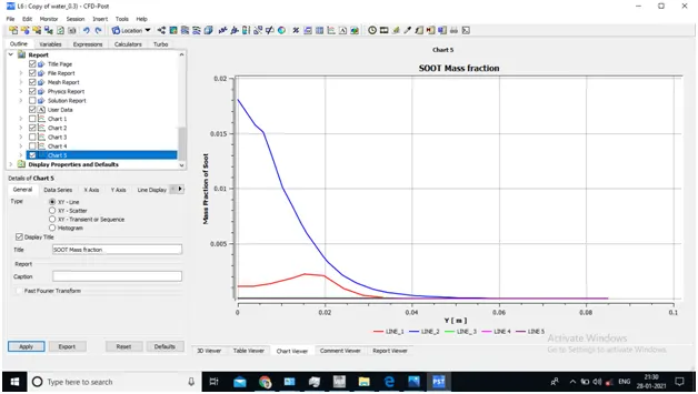
- SOOT MASS FRACTION CONTOUR
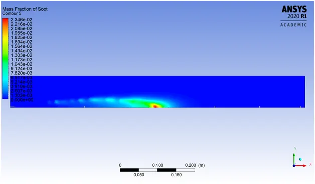
- SOOT MASS FRACTION VARIATION AT DIFFERENT LINE PROBE
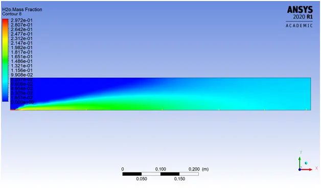
- H2O MASS FRACTION CONTOUR
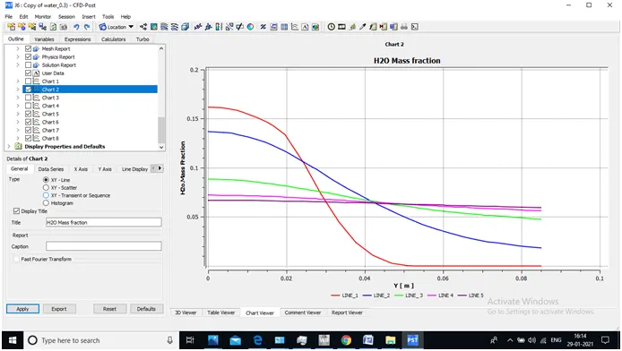
- H2O MASS FRACTION VARIATION AT DIFFERENT LINE PROBE
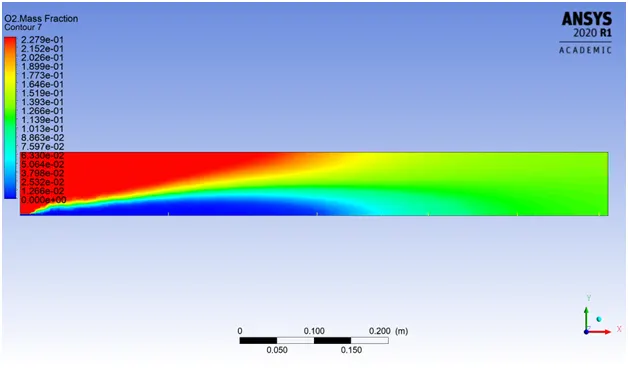
- O2 MASS FRACTION CONTOUR
- O2 MASS FRACTION VARIATION AT DIFFERENT LINE PROBE
- N2 MASS FRACTION CONTOUR
- N2 MASS FRACTION VARIATION AT DIFFERENT LINE PROBE
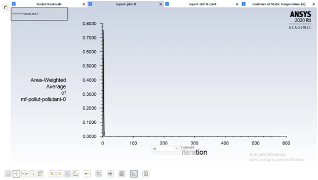
Area weighted avg. plot for outlet temp & No pollutant
RESULTS
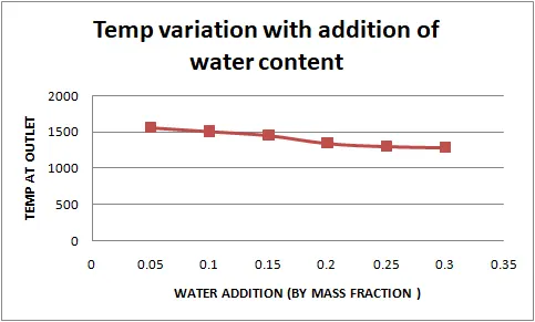
| % of Fuel content | % Mass content | Temp at outlet | Nox pollutant No. | Soot Pollutant No. | |||||||
| 0.95 | 0.05 | 1556 | 2.32E-05 | 0.000114 | |||||||
| 0.9 | 0.1 | 1505 | 7.04E-06 | 8.74E-05 | |||||||
| 0.85 | 0.15 | 1452 | 2.39E-06 | 6.54E-05 | |||||||
| 0.8 | 0.2 | 1344 | 1.09E-06 | 4.57E-05 | |||||||
| 0.75 | 0.25 | 1302 | 2.95E-07 | 3.30E-05 | |||||||
| 0.7 | 0.3 | 1287 | 8.67E-08 | 2.23E-05 | |||||||
CONCLUSION
- Here as Water content is increased ,Max temp decreases at the outlet and hence we can choose better material for burner
- NOx pollutant , Soot fraction also decreases as the water content increses.
- Soot Formation and NOx fraction in range of 1e-7 which indicates much less effect to environments.