Conjugate Heat Transfer Analysis on a graphics card.
OBJECTIVE : To perform graphics card Conjugate heat Transfer simulation and analyse wall heat transfer cofficient value for differet velocity of fluid.
Importance & Significance of CHT (CONGUGATE HEAT TRANSFER) :
- conduction refers to mode of heat transfer in specially in solid in which themal energy of transfer occured due to lattice vibration of molecules and due to energy sharing between moving free electrons whereas in fluid or gases modes of heat transfer occured due to convection in which movement of bulk fluid creates due to density difference .
- The term conjugate heat transfer (CHT) is used to describe processes which involve variations of temperature within solids and fluids, due to thermal interaction between the solids and fluids.
- Conjugate heat transfer corresponds with the combination of heat transfer in solids and heat transfer in fluids. In solids, conduction often dominates whereas in fluids.
CHT in Graphics card Unit :
- Graphics card unit is heart of any electronic device whenever calculation is performed on computer or mobile heat generates which needs to remove for efficient performance of equipment .
- Heat generates while calculation mainly on processor which made of silica layered treated as heat source .
- Most of time Processor is in contact with fins base and due to conduction heat conductsfrom processor to finbase and on top of finbase and due to multiple fins heat transfer area increases and due to convection between heated surface of fins and exposed air heat is exposed to surrounding temp .
- In base of processor solid base with same purpose of heat convection ultimately result in heat transfer .
Mainly following four parts included.
1). Pre-procesing
2). Meshing.
3). Solving .
4). Post- processing.
1). Pre-procesing :
- open spaceclaim by click on geometry load the model
- unable share topology and share prep from workbench
2). Meshing :
- create name selection as inlet & outlet
- Generate mesh to see basic default mesh
- Choose different mesh size for different name selection (body ) as per requirement here we will perform simulation for two different mesh size .
- Select enclosure as fluid media and other take as solid media.
3). Solving :
- Select steady state condition and pressure based solver .
- Enable energy as we are dealing with temperature behavour
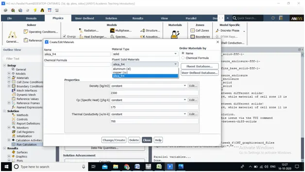
- For solid volume ie , fins base , processor , solid base underneath of processor we are going to use different material for each and thus material properties .
| Material | Parts | Themal_conductivity | specific heat capacity | Density |
| (w/m-k) | (j/kg-k) | (kg/m^3) | ||
| silica | Processor | 2300 | 175 | 700 |
| copper | Fins_base | 8978 | 387.5 | 381 |
| Aluminium | Solid_base | 2719 | 871 | 202.4 |
4. Select k-w SST turbulence model as our interest to capture wall effect better
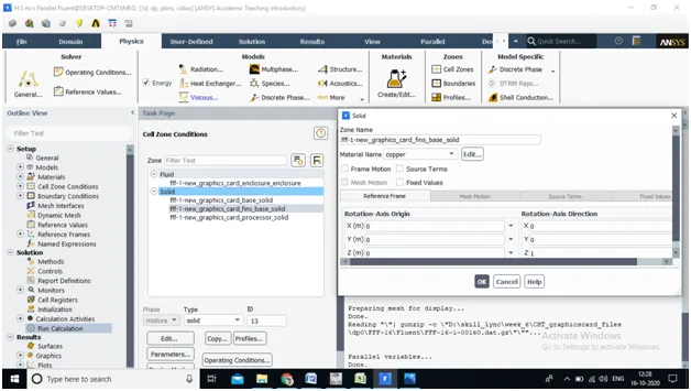
5. Check cell zone condition if theres any mismatch between geometry and assign material according to parts
6. Intialize solution and hit on calculate
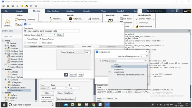
7. Here processor is heat generating part need to account as heat geratrated.
Heat gererated = heat /(volume of processor)
= 1.5 / ( 64*10e-9)
= 2.3e8
Boundary condition:
- Inlet air : 1m/s & Temp = 300 K (it can be varying according to simulation)
- Outlet : zero pressure (guage)
- Provide coupled Thermal condition
4). Post-processing :
- Create temperature & velocity counter at appropriate area
- Create vector plot & Stremline plot at appropriate plane .
- Create heat transfer coefficient plot at wall surface shadow.
DIFFERENT CASE :
- Coarse mesh for 1m/s , 3m/s and 5 m/s velocity
- Refined mesh for 1m/s , 3m/s and 5 m/s velocity.
- CASE-1 : Coarse mesh
- No. of element : 181107
- No, of Nodes : 32230
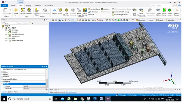
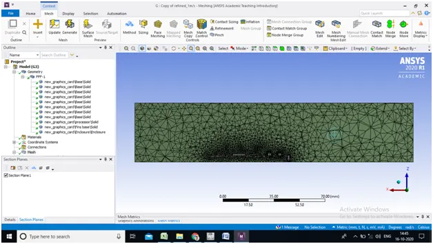
- Different mesh for different mesh size choosen as below with different method :
- Processor : Automatic Method
- Element size : 1.5 mm
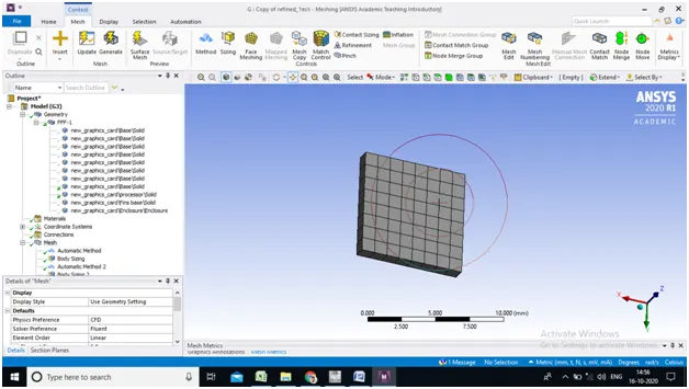
2. Solid base horizontal part : Automatic Method
- Element size : 1 mm
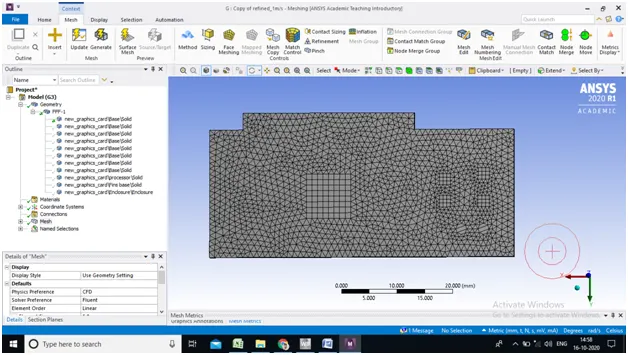
3. Solid base verticle part : Hex Dominant Method
- Element size : 1 mm
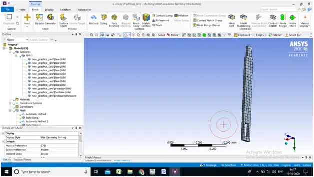
4. Finbase : Automatic Method
- Element size : 1 mm
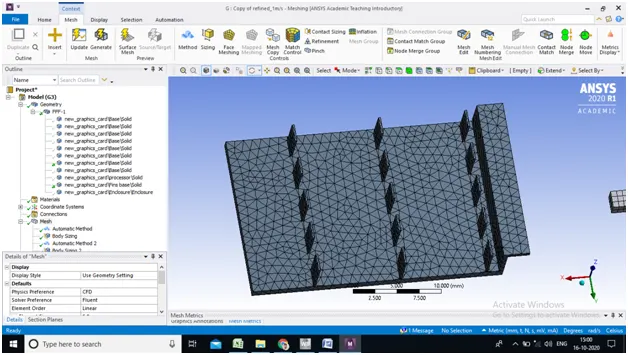
5. Miscellaneous part of Solid base : Automatic Method
- Element size : 0.75 mm
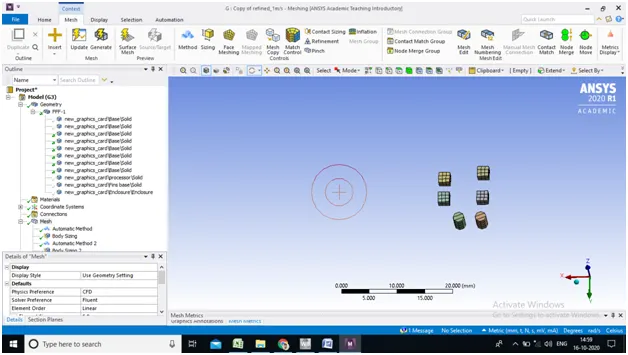
Coarse mesh : Velocity 1m/s
1.Residual Plot
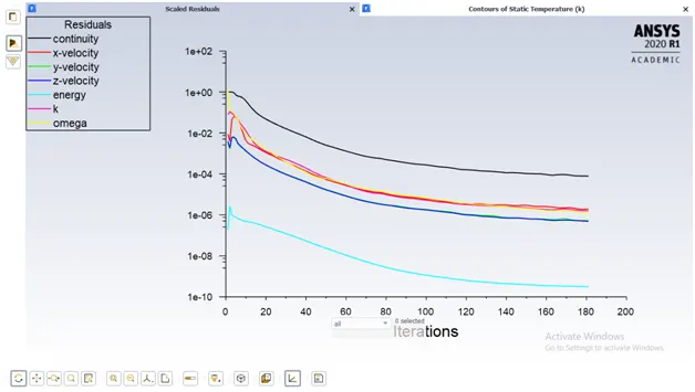
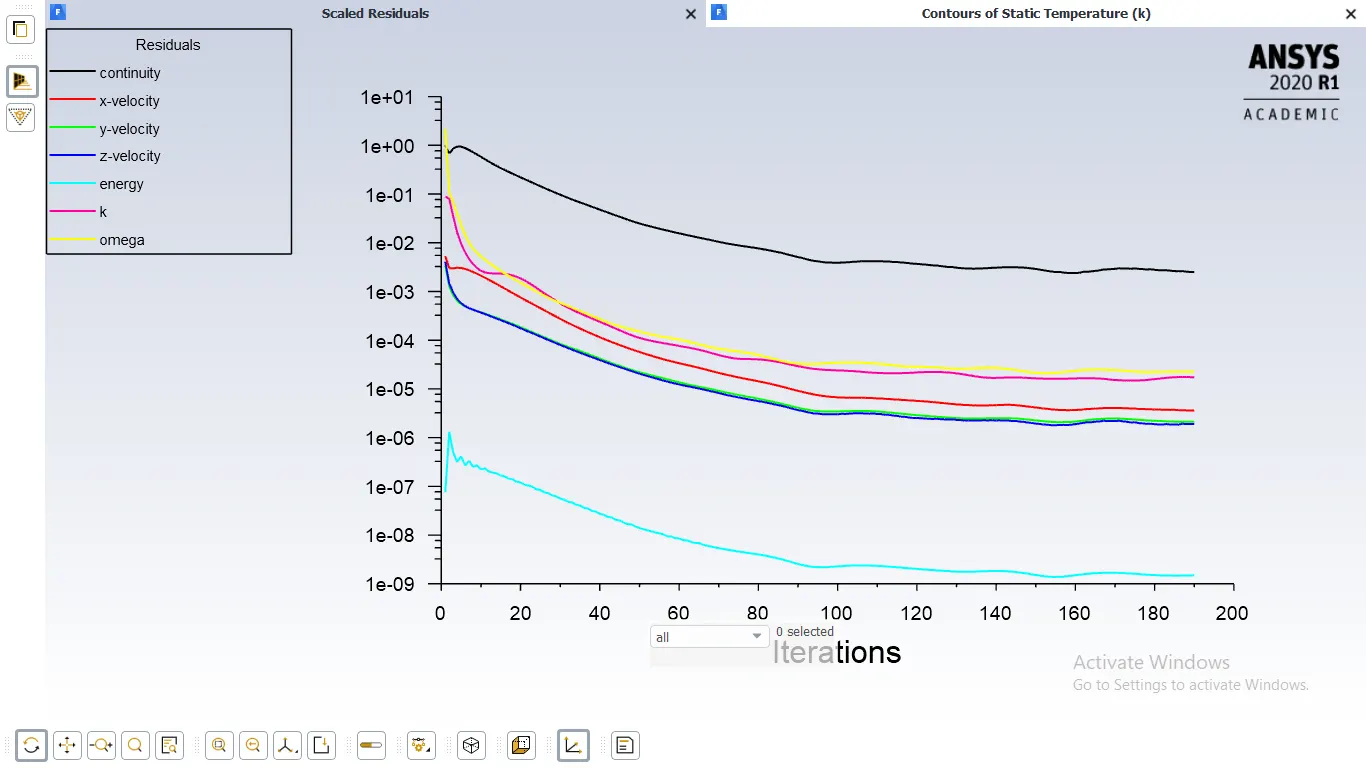
- Residual falls below tolerence and not fluctuates and gets converged.
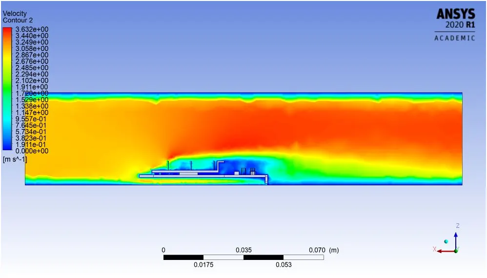
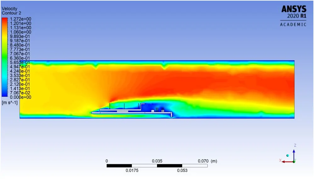
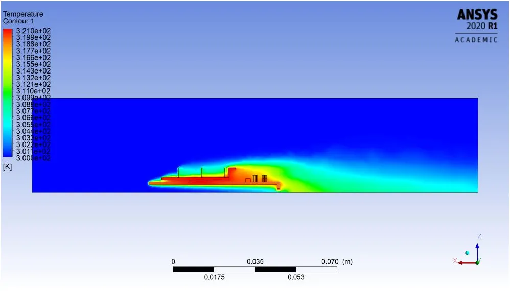
2.Velocity and Temperature contour
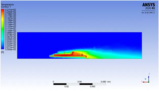
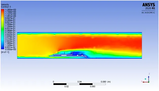
- from above plots Max. temp is observed here 321 k & max. velocity observed 1.26 m/s .
- velocity near the geometry observed as 0 M/S but as move further from geomerty velocity gets increases.
3.Local temp of different part
1). processor
2). finbase
3 ). solidbase
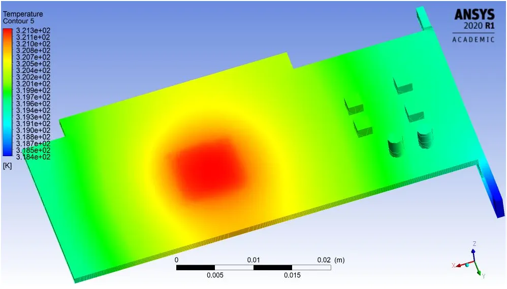
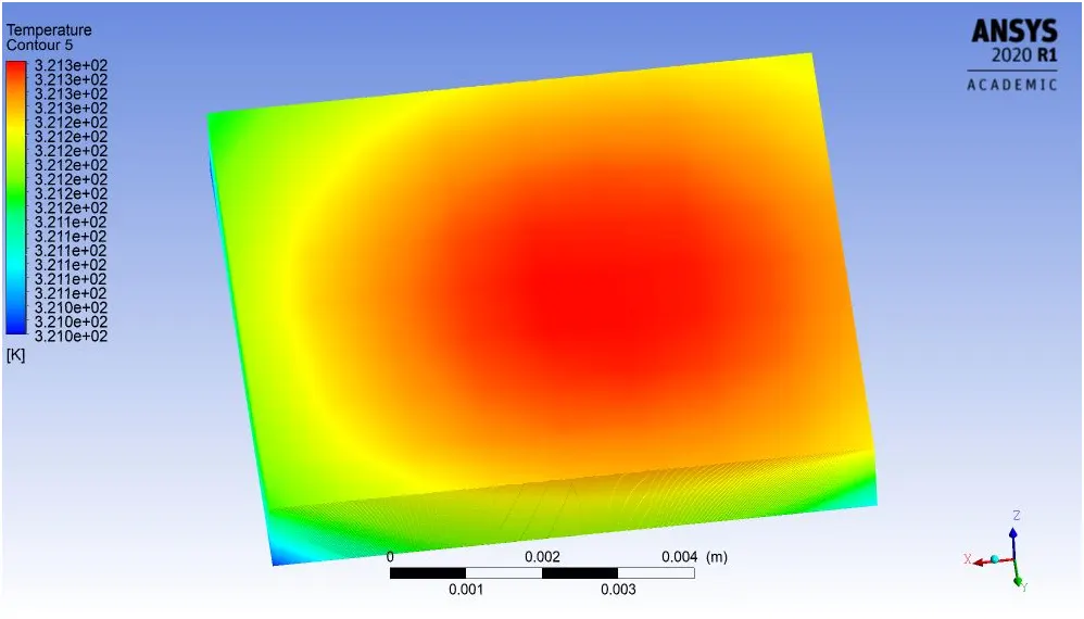
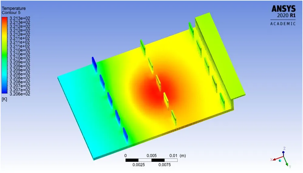
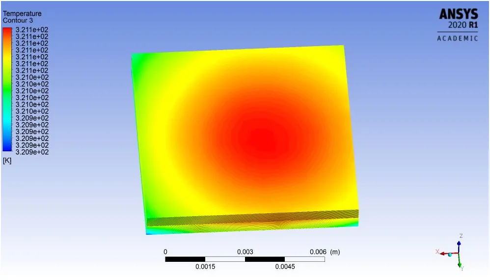
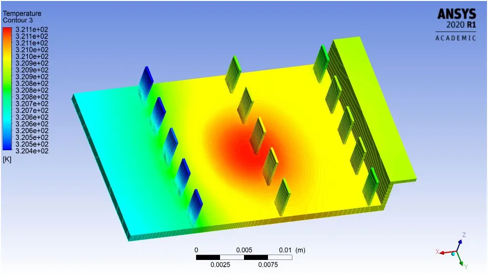
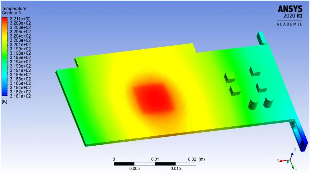
- Max. temp is observe here is 321k because of heat source and in case of finbase temp difference obseved as 1k & in case of solid base temp diference observed as 3K
- Temp is low in front part of area of finbase because velocity comes in contanct front parts first as air moves further forward temp. increses in that finbase .
- Potential hotspot where temp. is max is underneath of processor in solid base part .
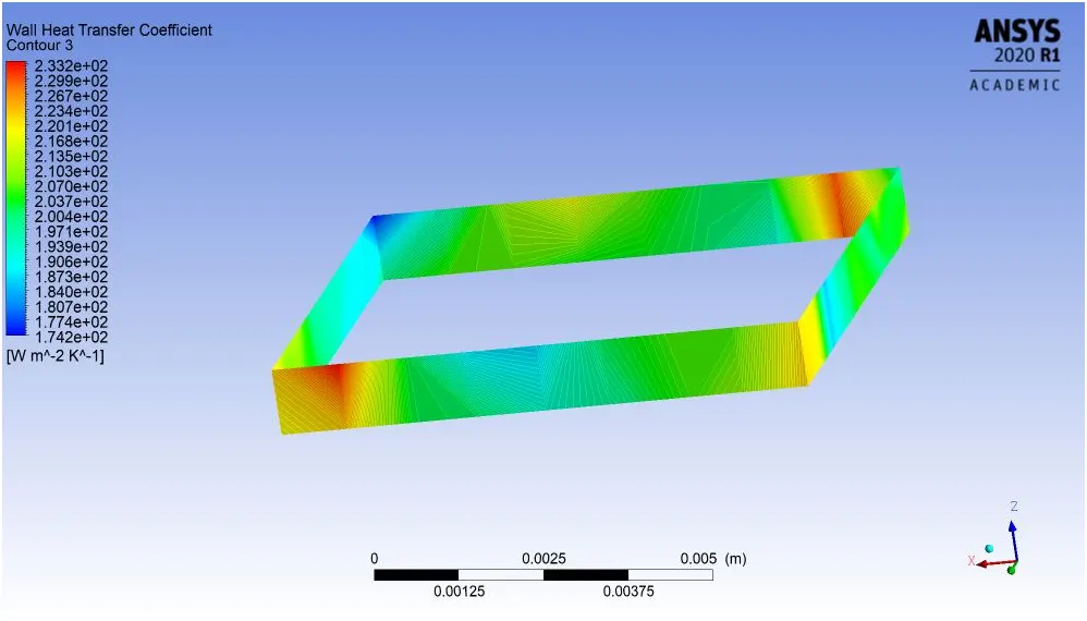
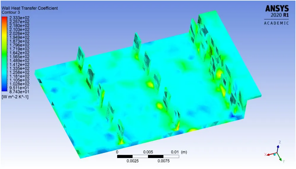
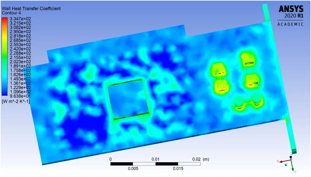
4.Local Wall Heat Transfer Coeffiecient for Different Parts:
1 ). Processor
2 ). finbase
3 ). solidbase
5.Velocity Streamline Plot
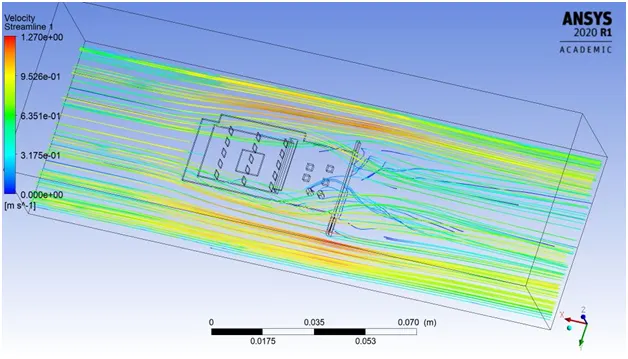
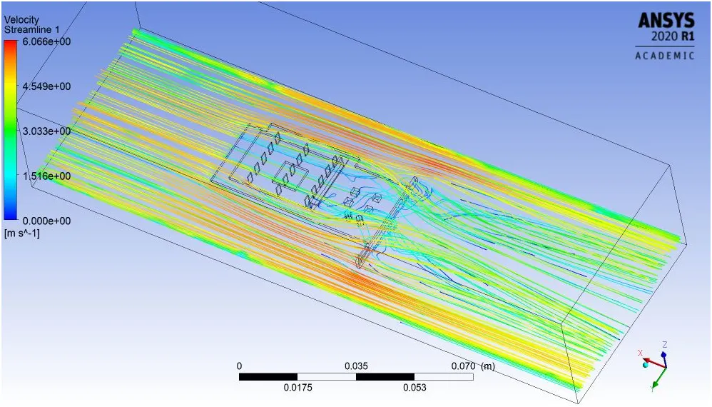
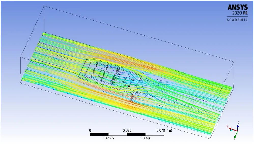
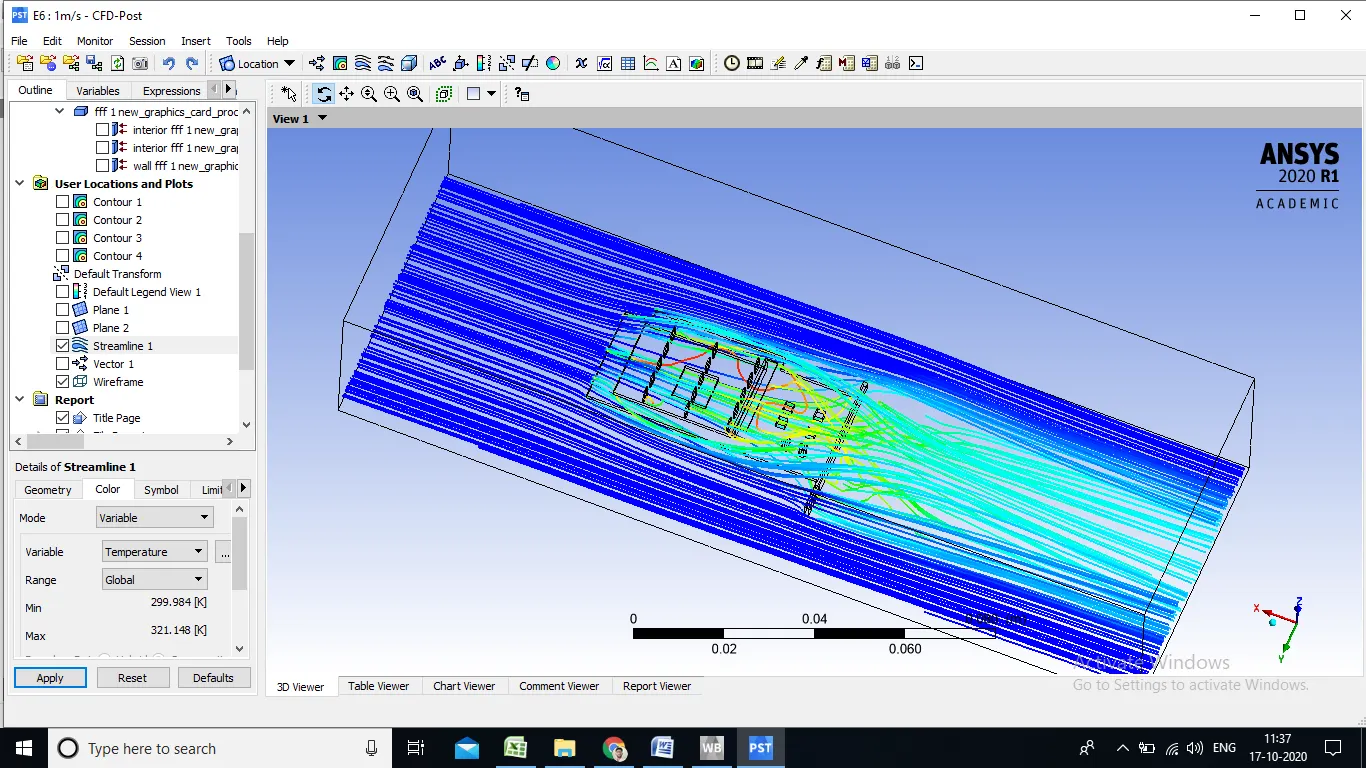
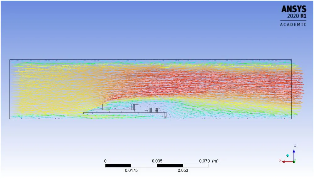
- when air stikes with lower solid base with velocity 1m/s air directs toward sideward of parts rather than follows staight motion and in both side velocity increses goes up to max. 1.27 m/s
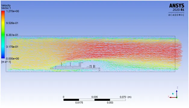
6.Velocity Vector Plot
Coarse mesh : Velocity 3 m/s
1.Residual Plot
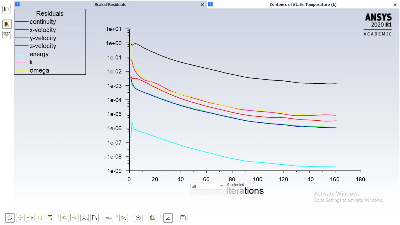
2.Velocity and Temperature contour
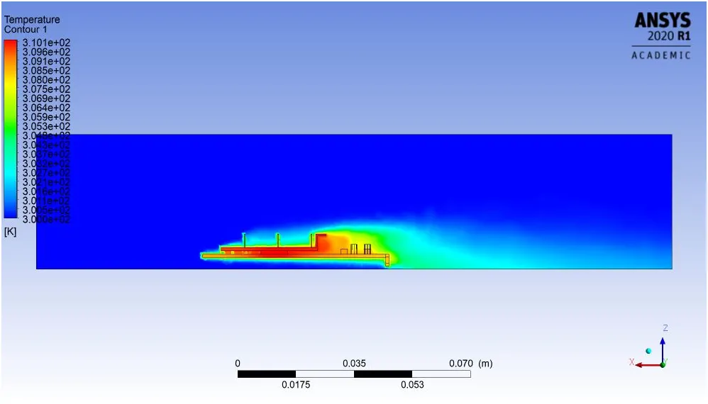
3.Local temp of different part
1). Processor
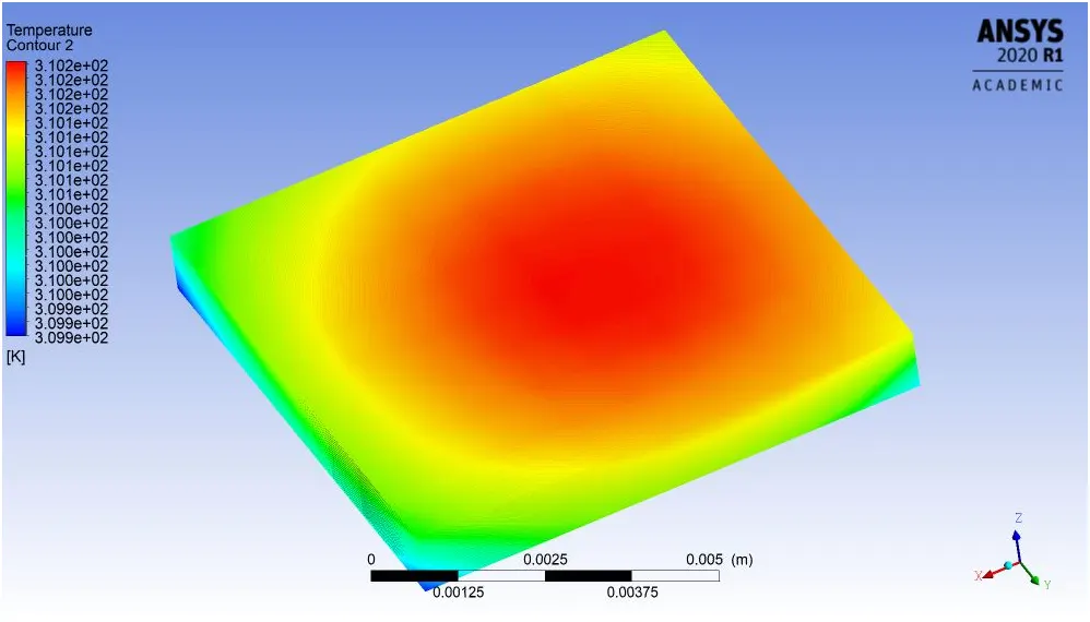
2). Finbase
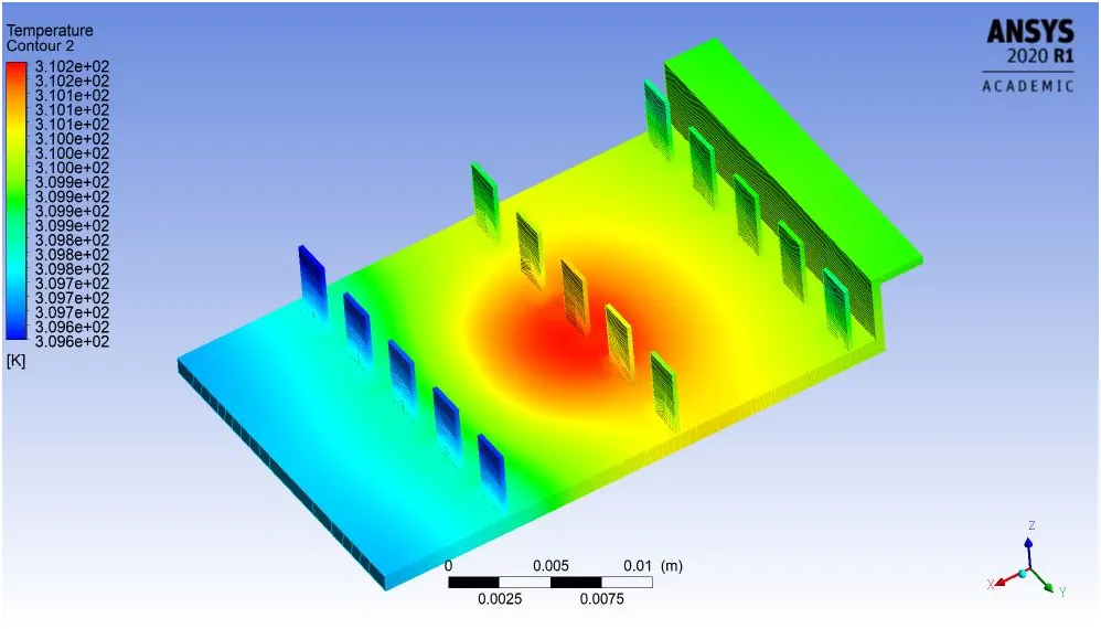
3). Solidbase
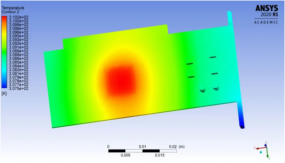
4.Local Wall Heat transfer co-efficient of different part
1). Processor
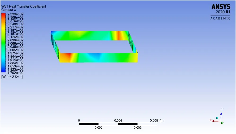
2). Finbase
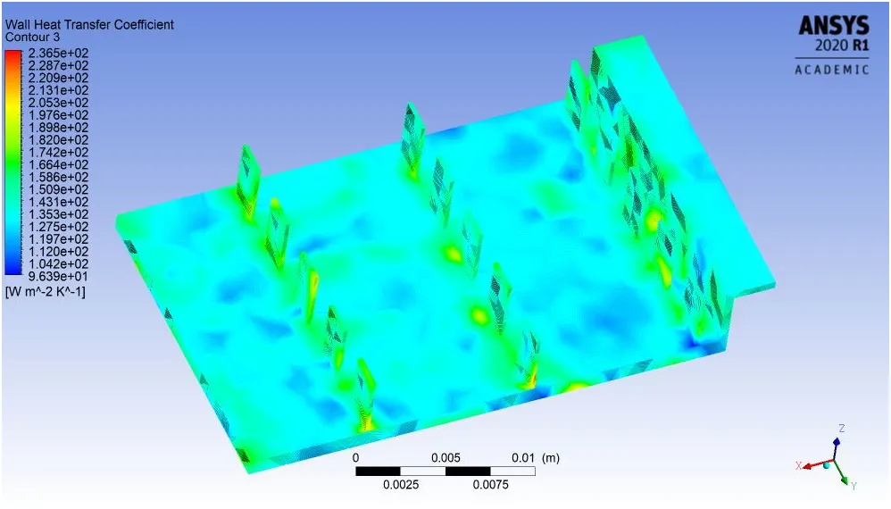
3). Solidbase
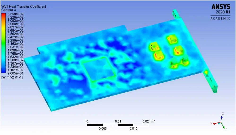
5.Velocity Streamline Plot
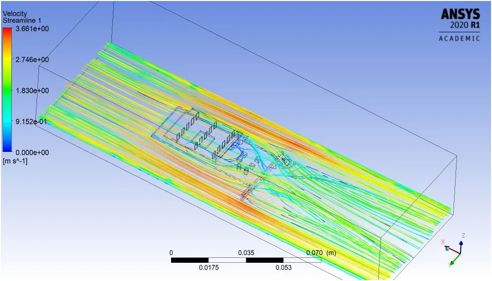
6.Velocity Vector Plot
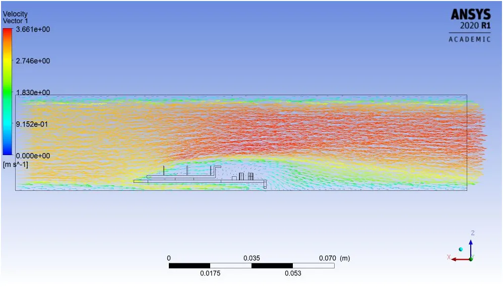
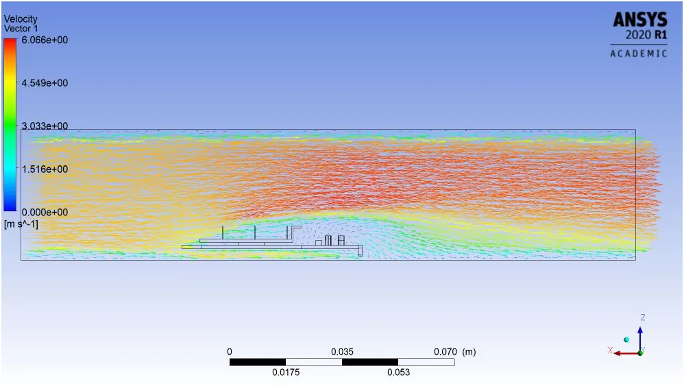
Coarse mesh : Velocity 5 m/s
1.Residual Plot
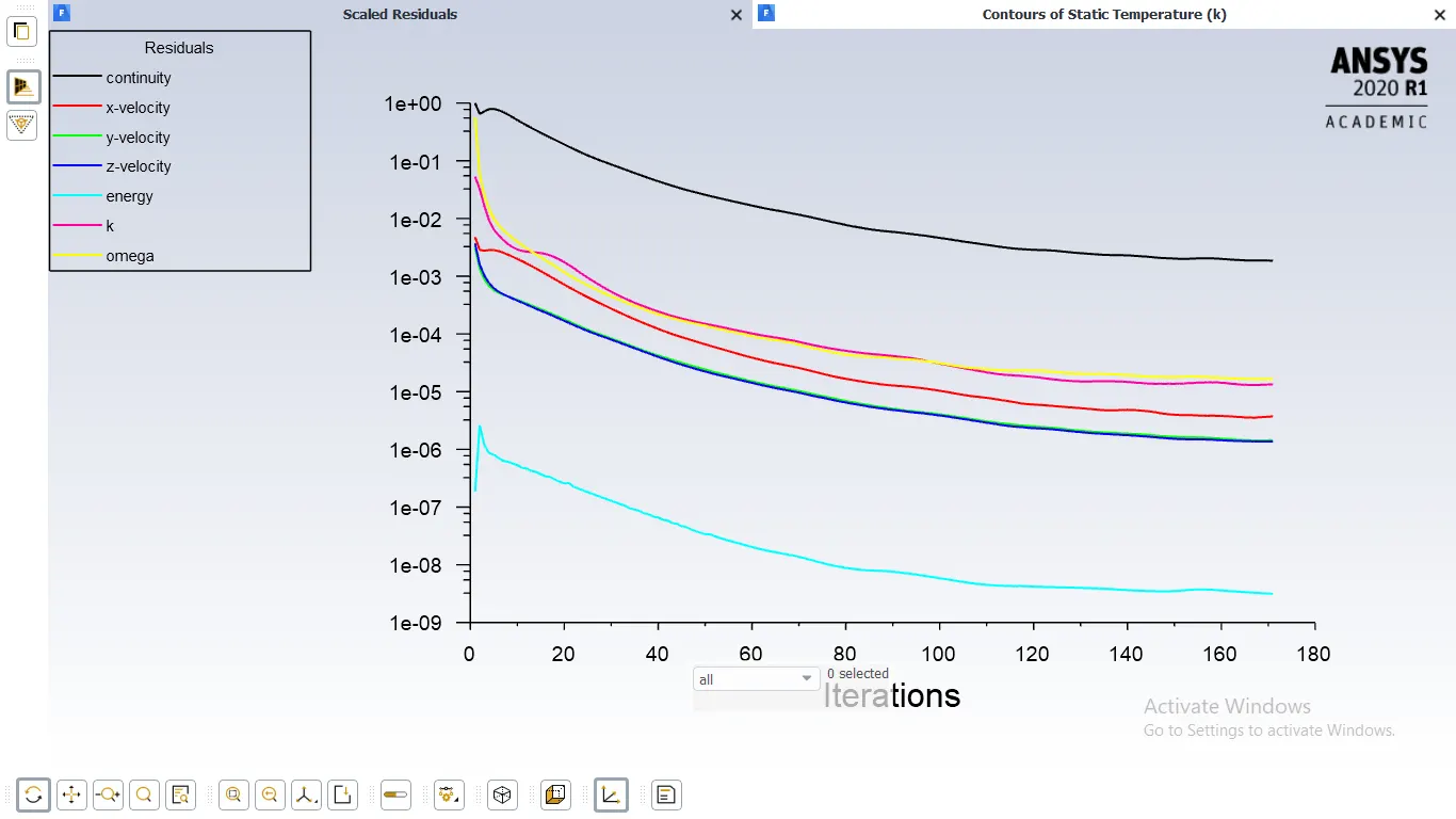
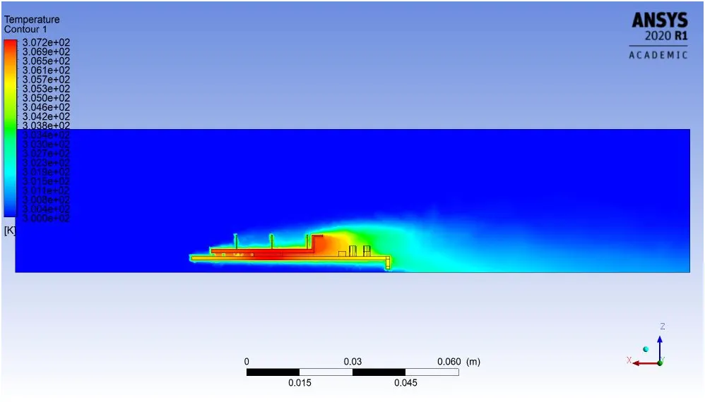
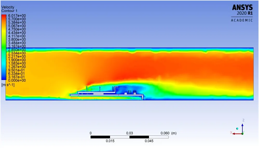
2.Velocity and Temperature contour
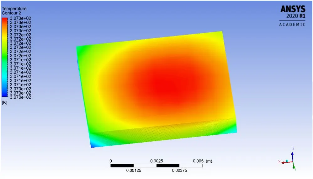
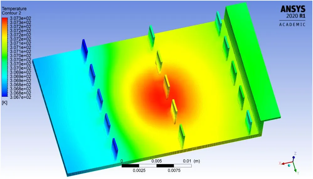
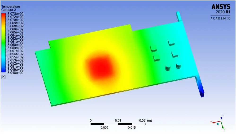
3.Local temp of different part
1). Processor
2). Finbase
3). Solidbase
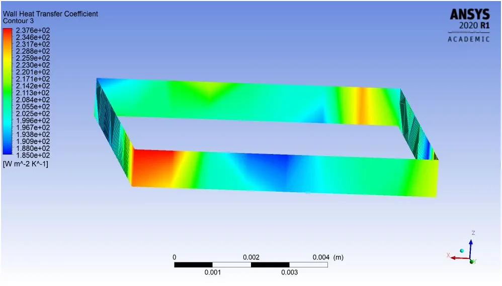
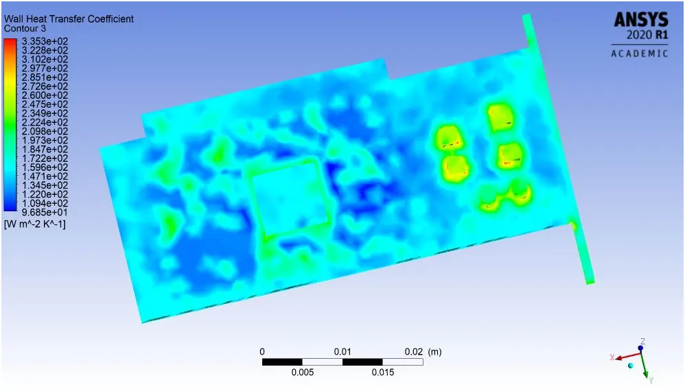
4.Local Heat Transfer co-efficient of different part
1). Processor
2). Finbase
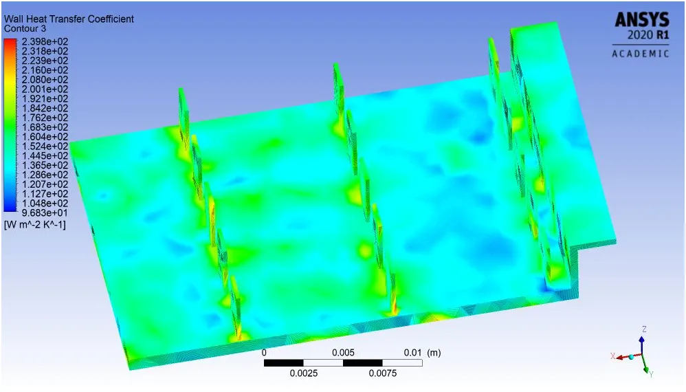
3). Solidbase
5.Velocity Streamline Plot
6.Velocity Vector Plot
- CASE-2 : Refined mesh
- No. of element : 491004
- No, of Nodes : 85265
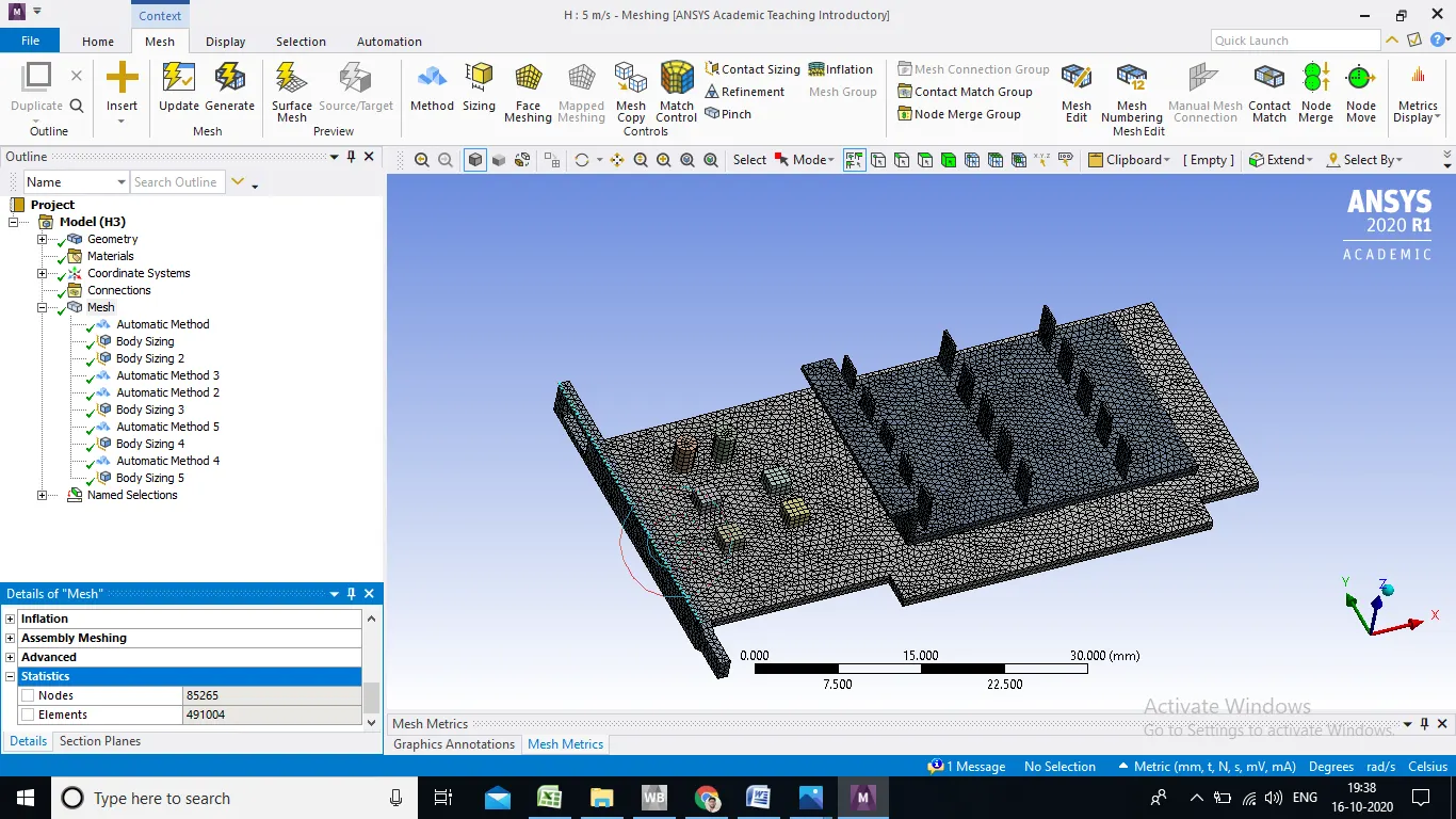
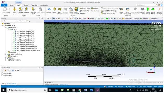
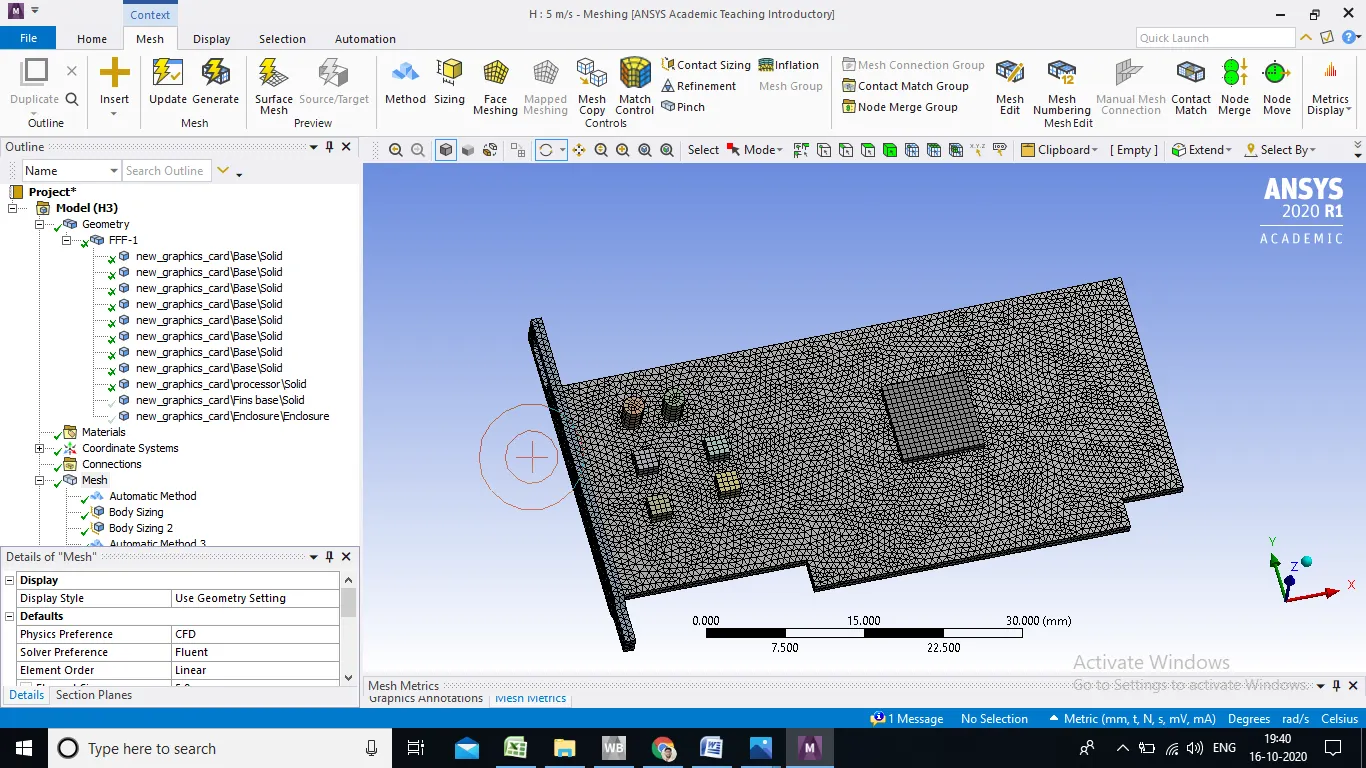
- Processor : Automatic Method
- Element size : 0.5 mm
- Solid base horizontal part : Automatic Method
- Element size : 0.6 mm
- Solid base verticle part : Hex Dominant Method
- Element size : 0.6 mm
- Finbase : Automatic Method
- Element size : 0.65 mm
- Miscellaneous part of Solid base : Automatic Method
- Element size : 0.5 mm
Refined mesh : Velocity 1 m/s
1.Residual Plot
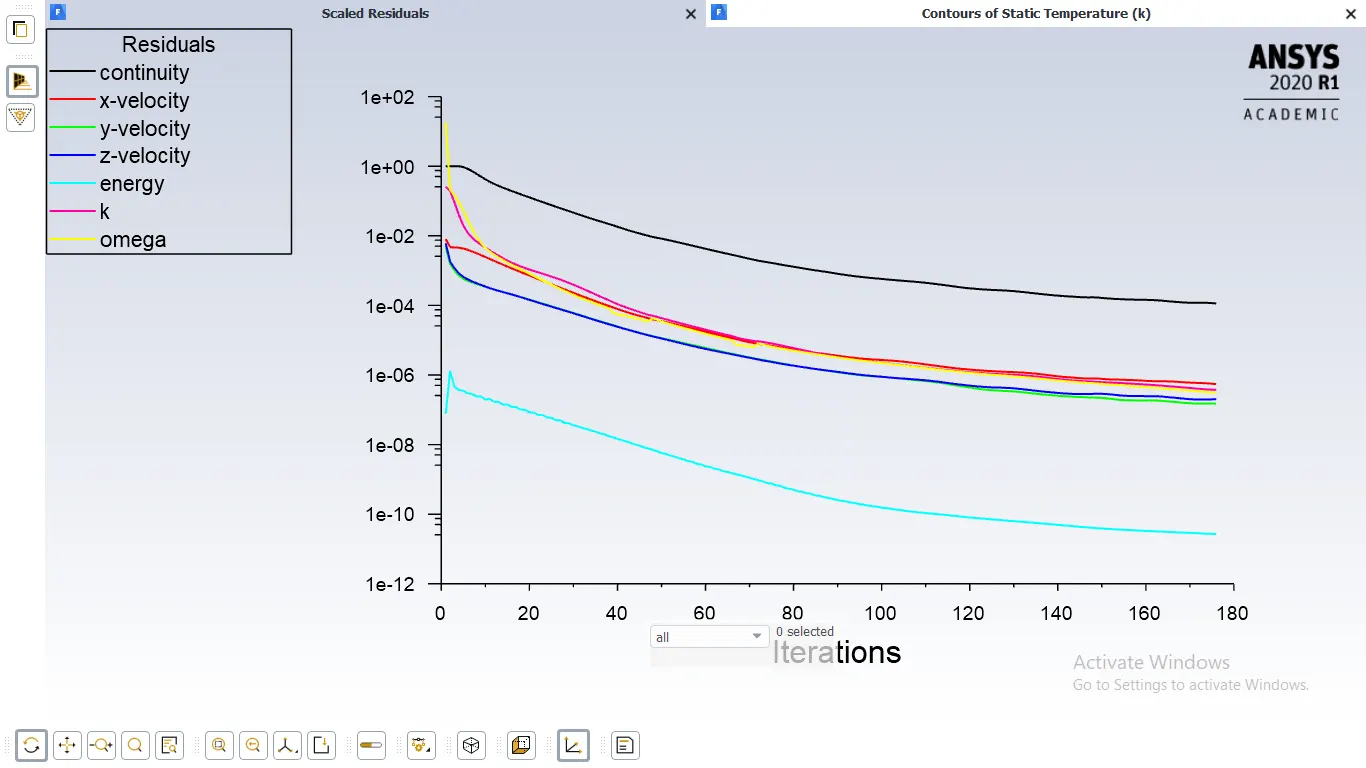
2.Velocity and Temperature contour
3.Local temp of different part
1). Processor
2). Finbase
3). Solidbase
4.Local Wall Heat Transfer co-efficient of different part
1). Processor
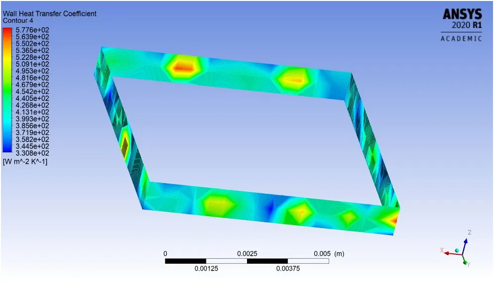
2). Finbase
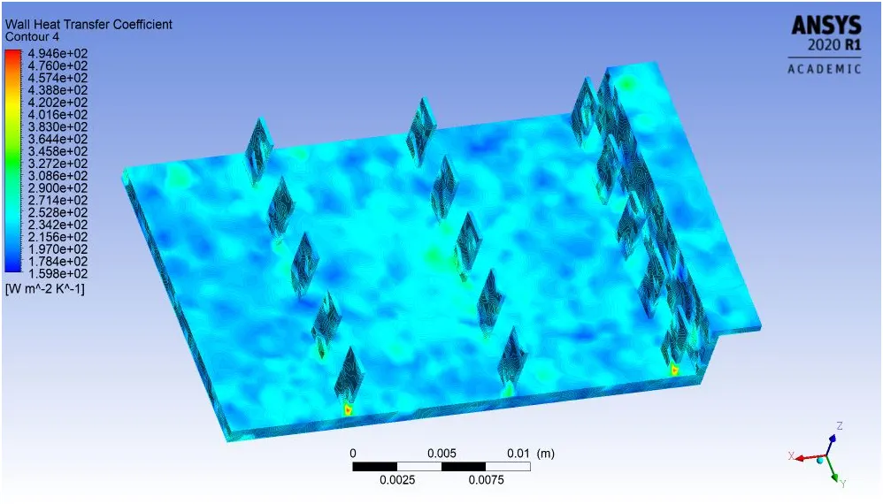
3). Solidbase
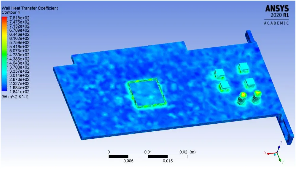
5.Velocity & Temp. Streamline Plot
6.Velocity Vector Plot
Refined mesh : Velocity 3 m/s
1.Residual Plot
2.Velocity and Temperature contour
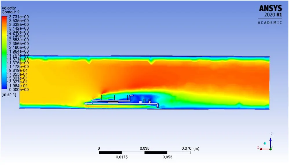
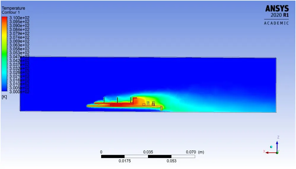
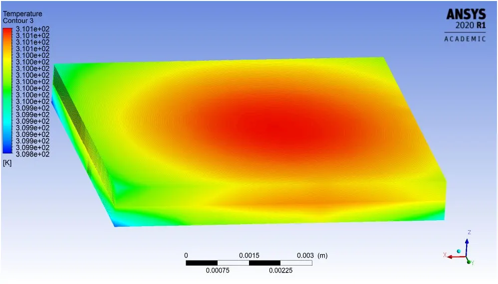
3.Local Temp. of different part
1). Processor
2). Finbase
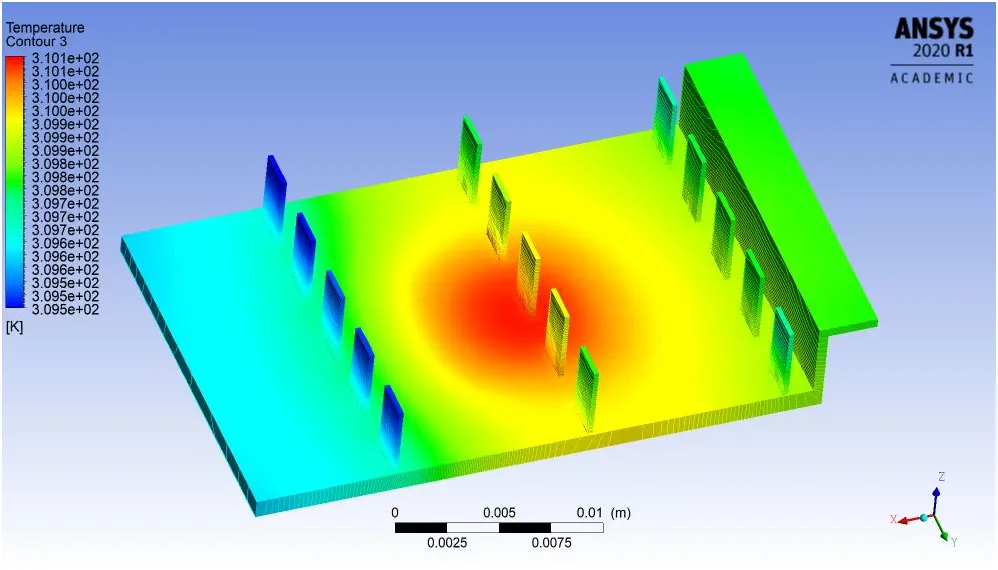
3). Solidbase
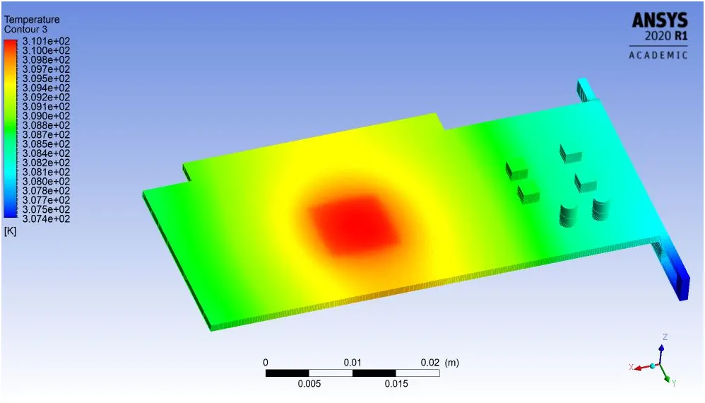
4.Local Wall Heat Transfer co-efficient of different part
1). Processor
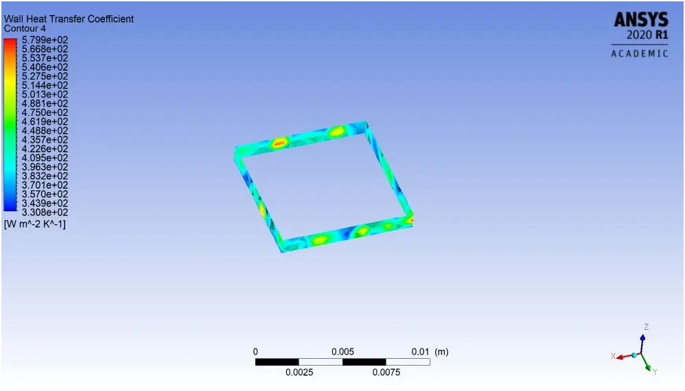
2). Finbase
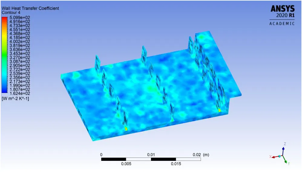
3). Solidbase
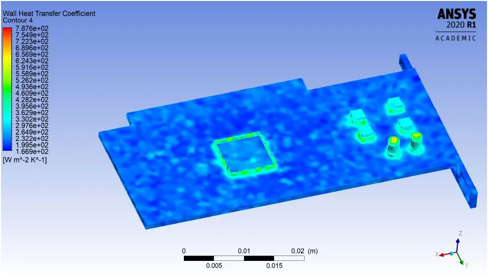
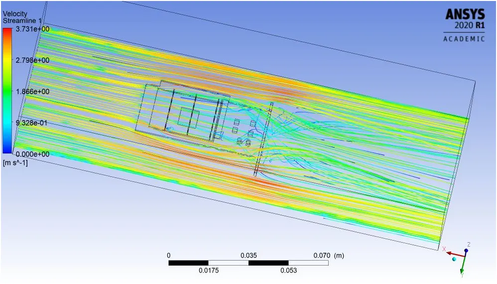
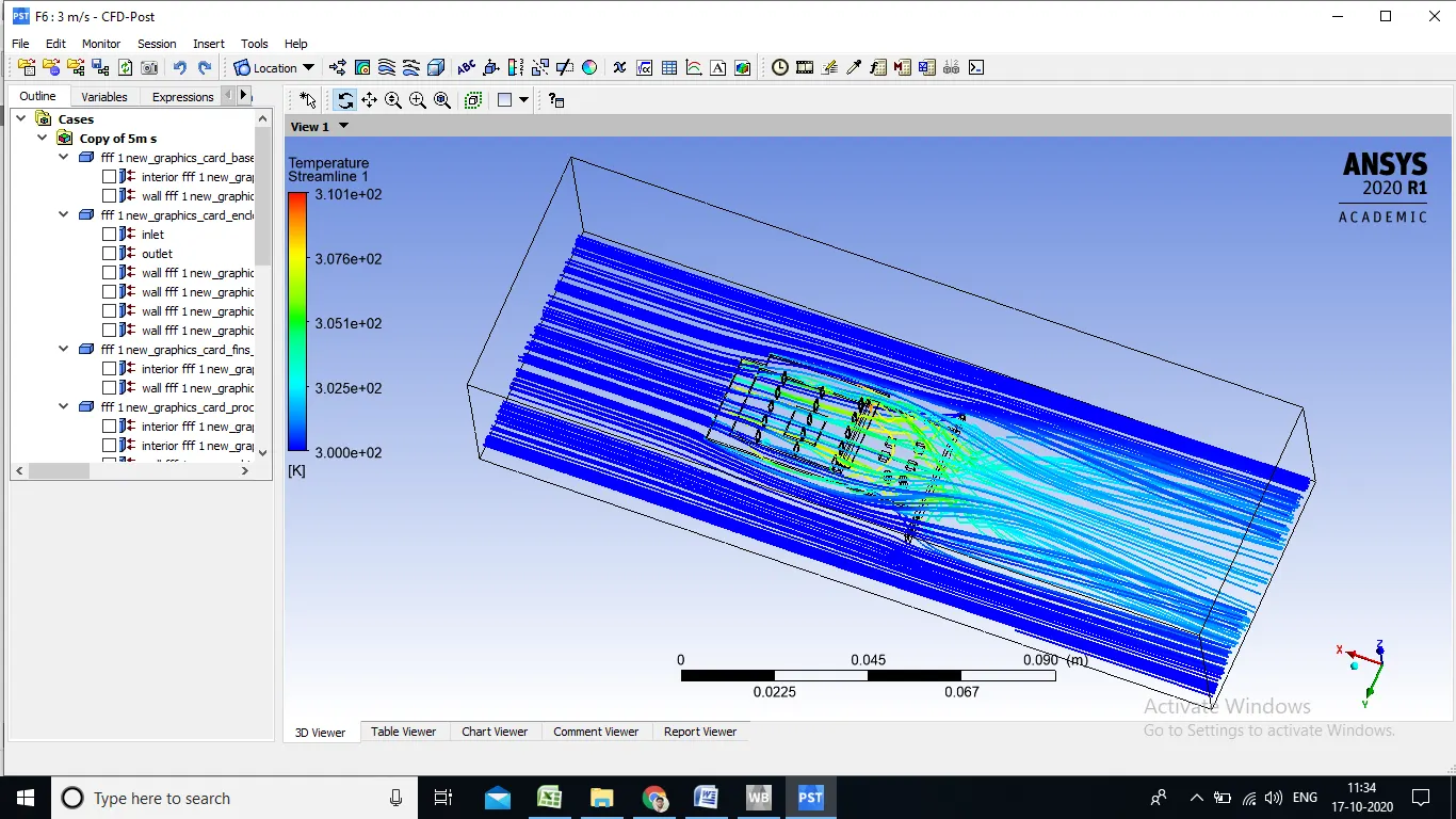
5.Velocity & Temp Streamline Plot
6.Velocity Vector Plot
Refined mesh : Velocity 5 m/s
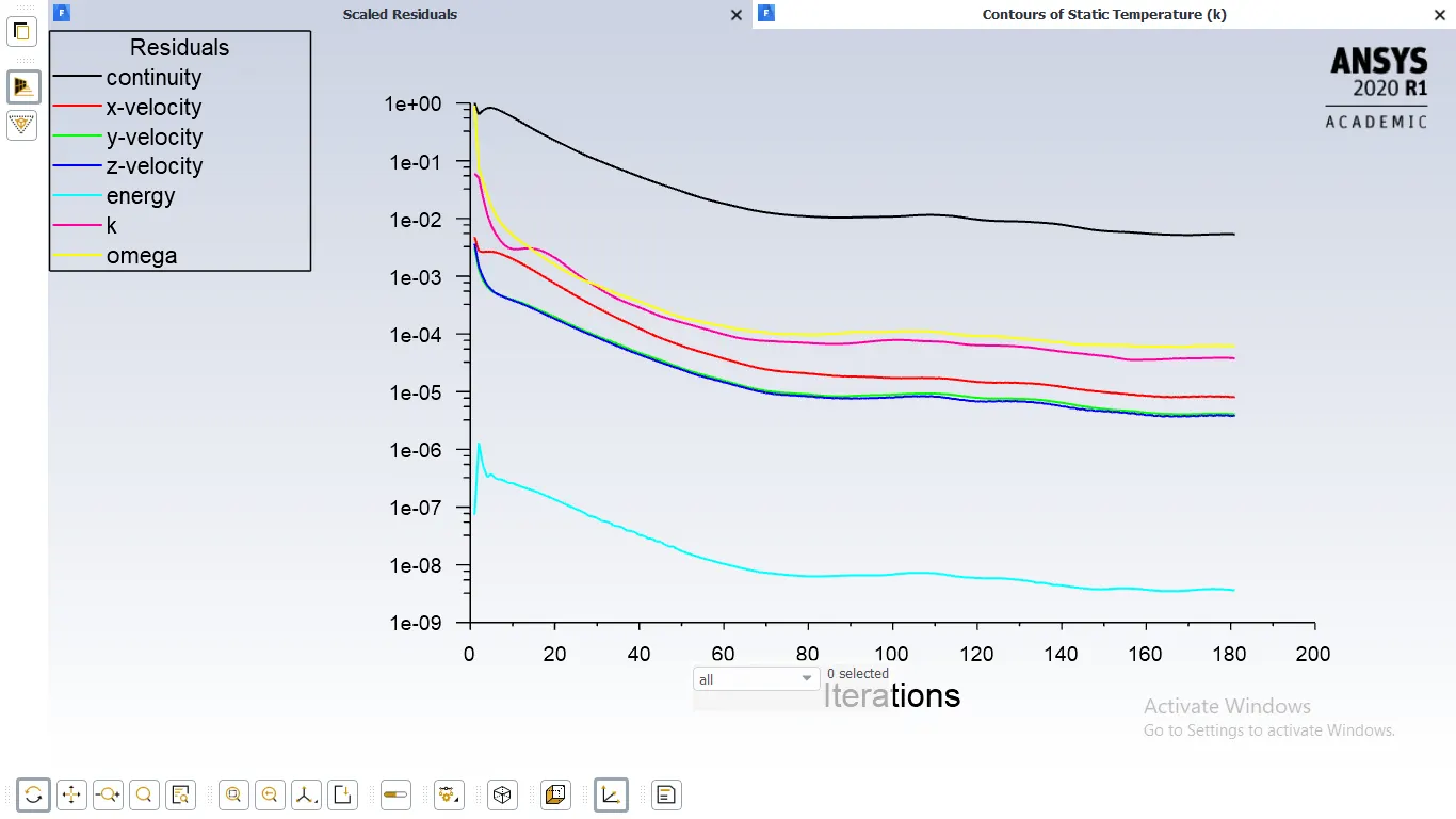
1.Residual Plot
2.Velocity and Temperature contour
3.Local Temp of different part
1). Processor
2). Finbase
3). Solidbase
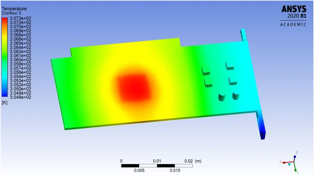
4.Local Wall Heat Transfer co-efficient of different part
1). Processor
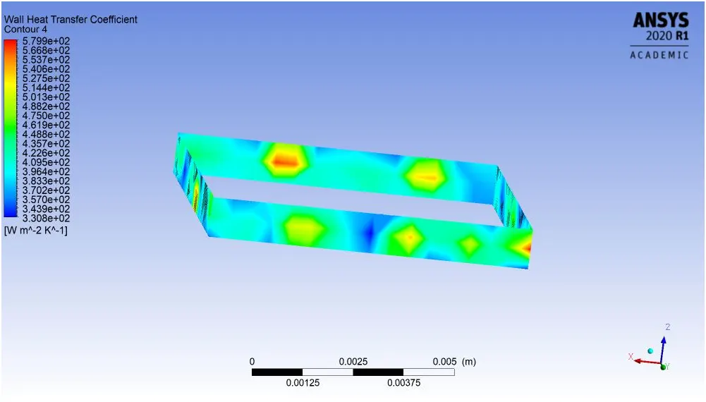
2). Finbase
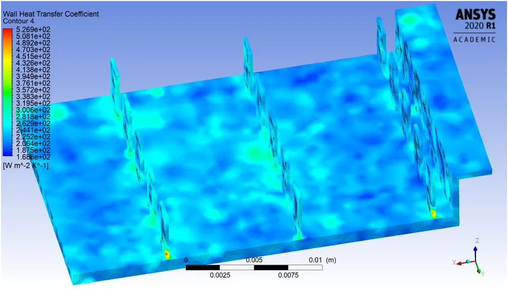
3). Solidbase
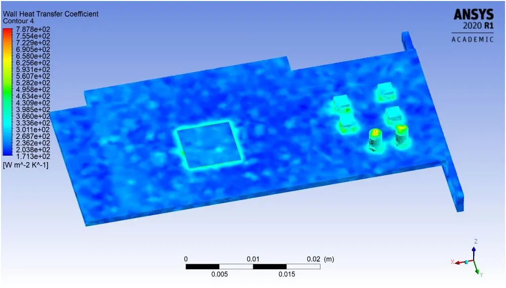
5.Velocity & Temp Streamline Plot
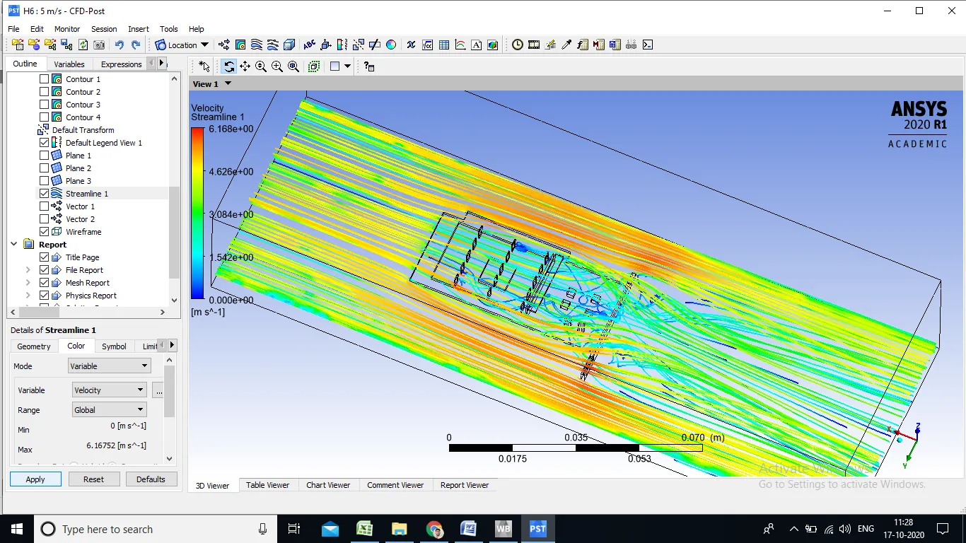
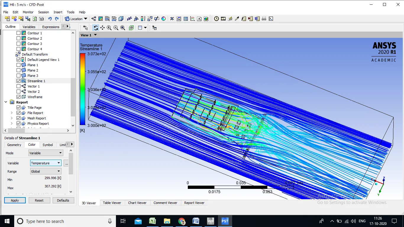
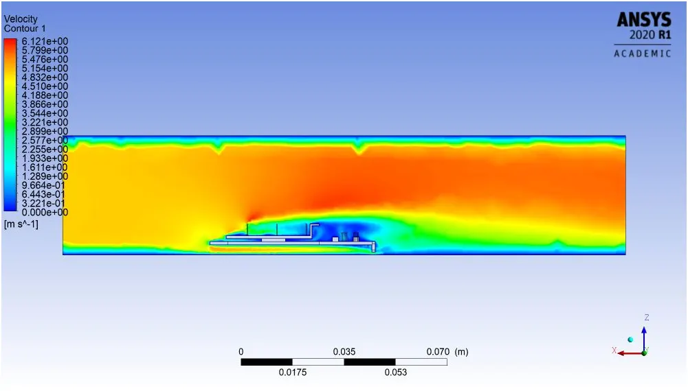
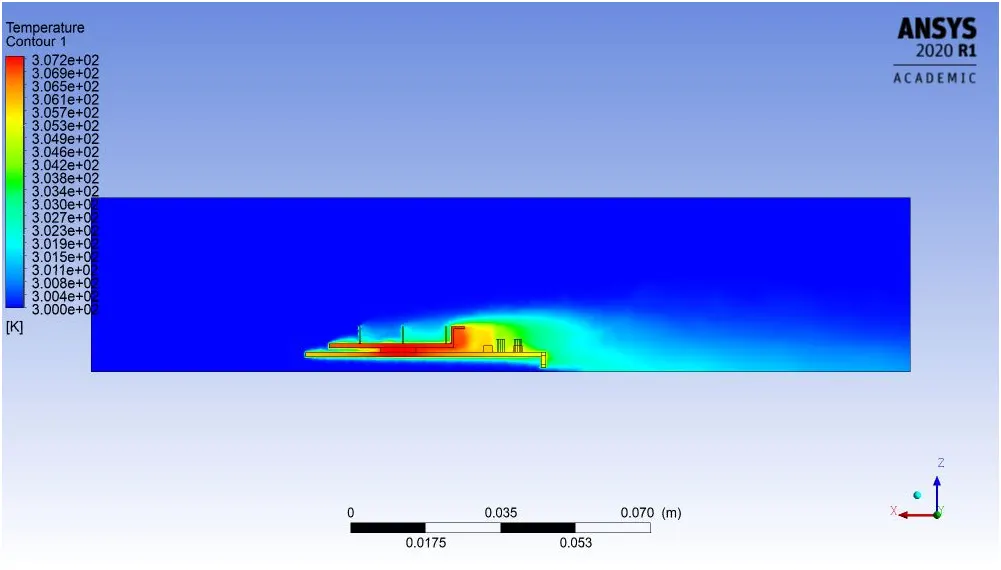
- when air stikes with lower solid base with velocity 5 m/s air somes of air directs toward sideward of parts ad somes follows staight motion also obseved some recirculation region and in both side velocity increses goes up to max. 6.17 m/s where temp also obseved max , due to convection air gets heated and icreases in the velocity
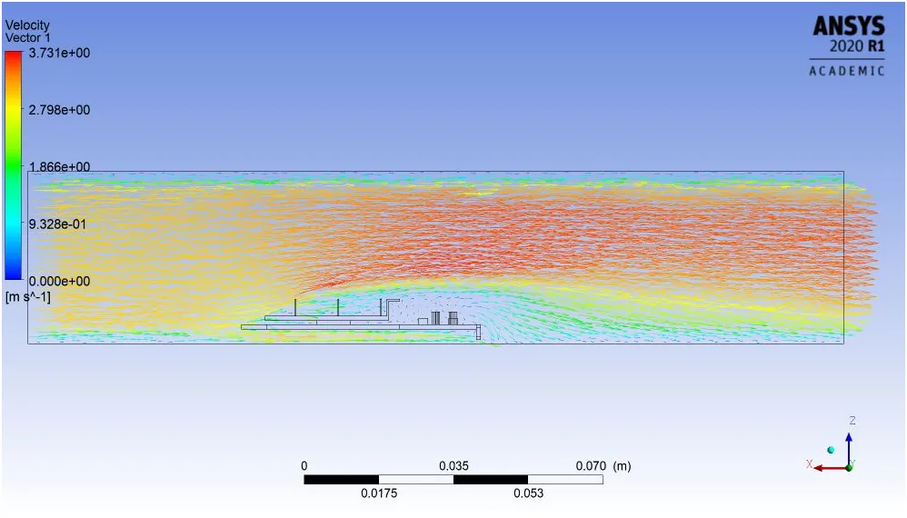
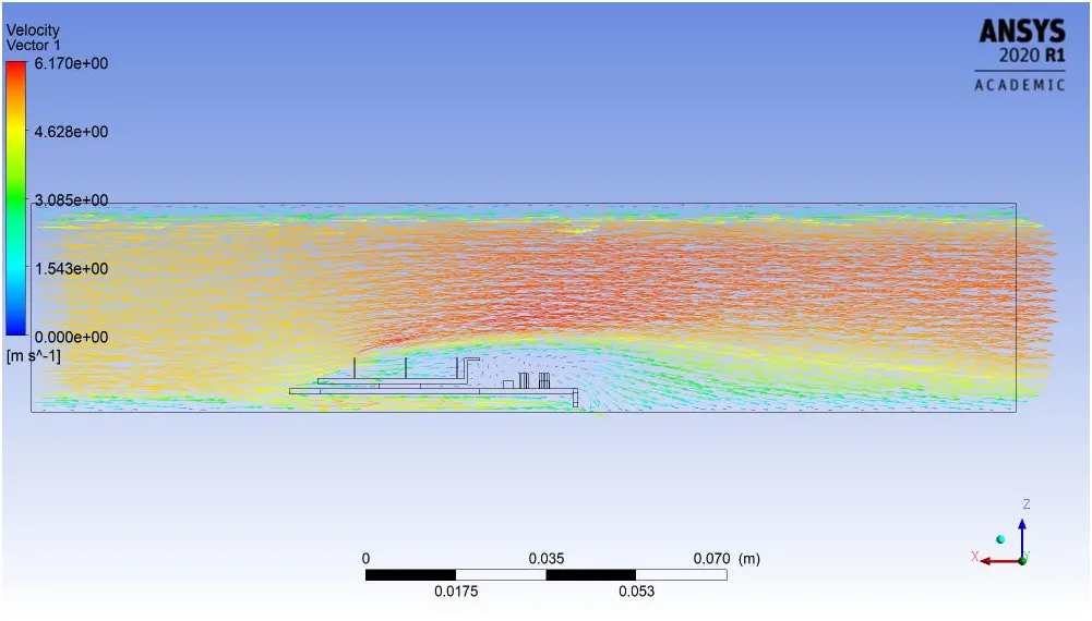
6.Velocity Vector Plot
- Reason of choosing particular mesh size & Mesh Method
- It is recomanded to use structural mesh most of time while simulation hence tried with hex dominant mesh , Multizone and Automatic Mesh Method .
- Because of cavity present & different parts sizes with curvature in the geomentry multizone is not working
- Then tried with Hex Dominant mesh as its relates with skewness of mesh but its so longer time to produce mesh other things it has created unwanted meh size and detoriated mesh quality.
- In this case Automatic mesh method creates mesh possible quality mesh according to geometry and parts curvature , size and present cavity and taking less time compared to other method to create mesh .
- CONCLUSION
- Finer mesh gives us better result compared to coarser mesh it can be seen from above plot
- With more finer mesh we can get high heat transfer co-efficient compared to coarser mesh which reduces temp, of processor
-
Temparture(K) Velocity WHTC velocity MAX MAX. MAX. MIN. 1m/s 321.1 1.26 334 87 Corse -mesh 3m/s 310 3.63 335.8 96.7 5m/s 307.2 6.01 335.8 96.8 1m/s 321 1.27 781 158.9 Refined-mesh 3m/s 310 3.73 787 162 5m/s 307 6.12 787.8 162.8 - With more refined mesh max. velocity is increses which result in heat dissipation.
- The heat transfer co-efficient max. available at base of processor
- one can go with high velocity air & Finer mesh to get good result and high Wall heat transfer co-efficient