Steady Vs Unsteady flow over a cylinder
- OBJECTIVE : : Simulate flow over cylinder with different reynold number for steady and transient condition and observe van karman vortex behind the cylinder and associates lift and drag .
- INTRODUCTION : when flow past over at low reynold number cylinder steamline is symmetrical to axis for both front and rear as well as upper side and lower side but as reynold no. increase symmetry starts to disappears with more in reynold no. increases more steamline behind the cylinder gets more wider and with increase in more reynold number because of flow sepration von karman vortex formation occurred.
which inlvolve series of clockwise voetex in upperhalf region and anticlockwise vortex in lowerhalf region of cylinder. This von karman vortex phenomena is still benchmark problem.
because of induced drag and lift if vortex shedding frequency match with natural frequency of with structure or body may be collapse. Thus its important to investigate darg and lift and accosiates lift and darg at different reynold number .
- Flow sepration :
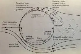
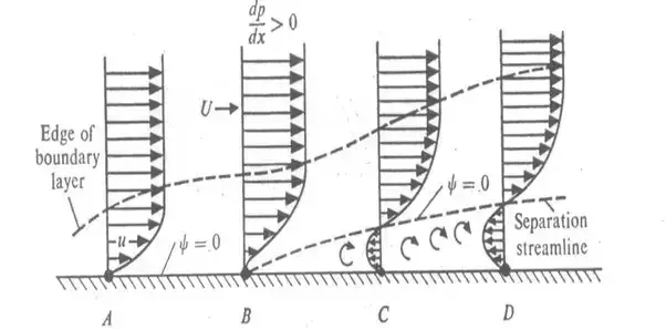
when fluid passes through body because of higher momentum in starting its find favourable pressure difference (dp/dx < 0) which causes fluid to flow in upstream but while flowing its continue loosing its momentum transfer due to viscosity of fluid and induced shear stress when momentum transfer is not capable to overcome friction force due to shear stress at that point velocity and pressure gradient can be seen as zero ( dp/dx=0 & dv/dx=0 ) point at which flow septares and as flow further move in upward direction because of positive pressure gradient (dp/dx > 0 ) due to that adverse pressure difference fluid start to flow back and produces vortex.
- Drag and lift :
Drag : drag is force created on body in opposite direction to its actual direction which may be because of difference in pressure on sides of body and due to skin friction of body.
Drag force = 0.5* cd * (rho * area * (velocity )^2 )
Where cd = co-efficient of drag
Initially at lower reynold number pressure distribution is indentical because of that produced net drag is due to only skin friction and thus no effect due to pressure drag . but as the reynold number increases drag due to skin friction disappears and due to pressure difference on both side its mainly due to pressure difference.
Lift : lift is force produced due to difference due to upperside and lowerside cylinder pressure difference .
Lift force = 0.5*cd* (rho * area * (velocity )^2 )
Where cl = co-efficient of lift .
Mainly following four parts included.
1). Pre-procesing
2). Meshing.
3). Solving .
4). Post- processing.
- PROCEDURE :
- After opening ansys workbench click on ansys fluent in toolbox and drag it into project schematic page as shown below:
- Pre- processing
It's include preparation of geometry which is being use in our simulation part .since we are using geometry in meter its required to convert unit change from milimeter to meter
create circle of diameter 2 meter with using comand circle after that create flow domain on left side (using construction line command ) of from center of drawn circle of 20 m as shown in figure same for right side 40m .
here it is neccesary to select right domain specially behind cylinder since our interest to show how fluid behave behind the cylinder otherwise if incorrect domain is select its may cause flow reversal problem instead of flowing in upstream.
delete all construction line that were used for construct geometry .
geometry specification :
- sphere diameteter : 2m
- in flow lengh : 20 m
- outflow length : 40 m
- Meshing
-
Select method from insert change the mesh size to 0.2 meter for fine mesh then select all triangular mesh
- create inflation layer of first layer thickness 0.005 m wit growth rate of 1.2
- select size to devide prefferd of divison into circle of 36 parts by selecting edge .
- solving
- Select pressure base solver type since we are dealing with low mach number.
- Select absolute in velocity formulation
- Selct steady state condition
- Selct mesh quality which will check mesh
- since we are using low reynold no. going to use laminar model as reynold goes more than 1000 we are using k-epsilon method
- reynold number = (density * velocity * characteristic length) / dynamic viscocity .
- here characteristic length depend on the shape of geometry .
- we are changing reynold number in our case by changing velocity with keeping constant density and viscosity.
- for that we have created user defined material as shown below from fluent material databse by copy air material properties and changes to user_defined.
- boundry condition :
- inlet = 1 m/s for reynold no=100 (change with respect to reynold no.)
- outlet = pressure 0 gauge pressure
- symmetry condition
- wall = no slip condtion & stationary wall.
- Post- processing :
- one point (monitor point ) is create along the lenght of flow 8m far from center of circle to observe velocity fluctuation on that point .
- with using report defination by using force drag and lift to be observerd at wall.
- velocity and pressure contour crated and accosiated animation to see effect over time while simulation.
- DIFFERENT CASE
- PART-I
- Simulate the flow with the steady and unsteady case and calculate the Strouhal Number for Re= 100.
- PART-II
- Calculate the coefficient of drag and lift over a cylinder by setting the Reynolds number to 10,100,1000,10000 & 100000. (Run with steady solver)
- PART-1
1). SIMULATE FLOW WITH STEADY STATE WITH REYNOLD NO=100
- ITERATION RUN =700
- RESIDUAL PLOT
- DRAG AND LIFT CO-EFFICIENT PLOT
- VELOCITY AND PRESSURE CONTOUR PLOT
- VORTEX AVG. OF VELOCITY PLOT
- PART-1
2) . SIMULATE FLOW WITH UNSTEADY STATE WITH REYNOLD NO=100
- NO. OF TIME STEP = 1350 & TIME STEP SIZE =0.1
- RESIDUAL PLOT
- DRAG AND LIFT CO-EFFICIENT PLOT
- VELOCITY AND PRESSURE CONTOUR PLOT
- VORTEX AVG. OF VELOCITY PLOT
- Here from above plot of steady and unsteady plot fluctuation in residual not observed with incresing in number of iteration its indication of solution is converged .
- vertex average of velocity magnitude reach where magnitude of peak value with incrase in no, of itearation not changing that means its reach to steady state condition there will be no change in magnitude if iteration or no. of step is increse.
- from above plot comparison of lift and drag is shown as below .
| DRAG_COEFFICIENT | LIFT_COEFFICIENT | |||||
| STEADY_STATE | 1.3184 | 0.1329 | ||||
| UNSTEADY_STATE | 1.285 | 0.227 | ||||
- To calculate below equation is strohual no. equation
st = (f*L) / U
WHERE f= vertox frequency (no, of peak in given time)
L = characteristic length
U = Free stream velocity
- since strouhal no. is related to no. of time step we cant get strouhal no. for steady state case as its purely depend on no. iteration.
f= 3 / (130-110) ( 3 peak in between flow time 110 to 130 is observe)
= 0.15
- st = 0.15 * 2 /( 1) ( for re=100 velocity =1)
= 0.3
- PART-II
- Calculate the coefficient of drag and lift over a cylinder by setting the Reynolds number to 10,100,1000,10000 & 100000. (Run with steady solver)
- SIMULATE FLOW WITH STEADY STATE WITH REYNOLD NO=10
- ITERATION RUN =700
- RESIDUAL PLOT
- DRAG AND LIFT CO-EFFICIENT PLOT
- The value for cd & cl are found as 3.35 and 0.0012
- VELOCITY AND PRESSURE CONTOUR PLOT
- VORTEX AVG. OF VELOCITY PLOT
2). SIMULATE FLOW WITH STEADY STATE WITH REYNOLD NO=100
- ITERATION RUN =700
- RESIDUAL PLOT
- DRAG AND LIFT CO-EFFICIENT PLOT
- VELOCITY AND PRESSURE CONTOUR PLOT
- The value for cd & cl are found as 1.318 and 0.132
- VORTEX AVG. OF VELOCITY PLOT
- ITERATION RUN =800
3).SIMULATE FLOW WITH STEADY STATE WITH REYNOLD NO=1000
- ITERATION RUN =700
- RESIDUAL PLOT
- DRAG AND LIFT CO-EFFICIENT PLOT
- The value for cd & cl are found as 0.914 and 0.57
- VELOCITY AND PRESSURE CONTOUR PLOT
- VORTEX AVG. OF VELOCITY PLOT
4). SIMULATE FLOW WITH STEADY STATE WITH REYNOLD NO=10000 & with K-e model
- ITERATION RUN =700
- RESIDUAL PLOT
- DRAG AND LIFT CO-EFFICIENT PLOT
- The value for cd & cl are found as 0.785 and 0.28
- VELOCITY AND PRESSURE CONTOUR PLOT
- VORTEX AVG. OF VELOCITY PLOT
5 ). SIMULATE FLOW WITH STEADY STATE WITH REYNOLD NO=100000 & K-e model
- ITERATION RUN =700
- RESIDUAL PLOT
- DRAG AND LIFT CO-EFFICIENT PLOT
- The value for cd & cl are found as 0.5640 and 0.468
- VELOCITY AND PRESSURE CONTOUR PLOT
- VORTEX AVG. OF VELOCITY PLOT
6 ). SIMULATE FLOW WITH STEADY STATE WITH REYNOLD NO=1000000 & K-e model
- ITERATION RUN =700
- RESIDUAL PLOT
- DRAG AND LIFT CO-EFFICIENT PLOT
- The value for cd & cl are found as 0.429 and 0.462 respectively in this case
- VELOCITY AND PRESSURE CONTOUR PLOT
- VORTEX AVG. OF VELOCITY PLOT
RE=10
RE=100
RE=1000
CONCLUSION :
- at low reynold number ( Re=100 ) cylinder steamline is symmetrical to axis for both front and rear as well as upper side and lower side but as reynold no. increase ( re=100, 1000) symmetry starts to disappears (with increse reynold no. inertian force starting to domanating over viscous force) as shows in stream line plot with more in reynold no. increases more steamline behind the cylinder gets more wider and with increase in more reynold number because of flow sepration von karman vortex formation occurred.
- lift is contiously varying with respect to iteration as its behaviour of fluctucting we cant get const. value for particular iteration so we are taking as max. value from zero once its reaches to steady state condiation.
- At low Reynolds Number as the flow is laminar, there's a large recirculation area behind the sphere thus the majority of the drag is in form of pressure drag. As the flow becomes turbulent, the flow remains attached to the sphere for longer. Hence, the pressure drag reduces and in most plots you see a decrease in drag
- For different reynold number simulation run successfully as shown drag co-efficient for differnt re no.
| REYNOLD _NO | DRAG_COEFFICIENT | AVG_VORTEX_VELOCITY | ||||||
| 10 | 3.351 | 0.059 | ||||||
| 100 | 1.318 | 0.483 | ||||||
| 1000 | 0.914 | 7.85 | ||||||
| 10000 | 0.785 | 78.67 | ||||||
| 100000 | 0.564 | 846.4 | ||||||
| 1000000 | 0.429 | 8277.5 | ||||||
- publication / reserch paper used :
- Journal of Wind Engineering and Industrial Aerodynamics, 35 (1990) 237-257 237 Elsevier Science Publishers B.V., Amsterdam -- Printed in The Netherlands
- Two-dimensional compressible viscous flow around a circular cylinder Daniel Canuto1† and Kunihiko Taira1
- https://en.wikipedia.org/wiki/Strouhal_number
- INTERNATIONAL JOURNAL FOR NUMERICAL METHODS IN FLUIDS, VOL. 11,985-1000 (1990)
TRANSIENT FLOW PAST A CIRCULAR CYLINDER: A BENCHMARK SOLUTION
MICHAEL S. ENGELMAN AND MOHAMMAD-ALI JAMNIA Fluid Dynamics International, Evanston, IL 60201, U.S.A. - A fundamental study of the flow past a circular cylinder using Abaqus/CFD Masami Sato, and Takaya Kobayashi.