Gate Valve Parametric Study
OBJECTIVE : To simulate flow through gate valve for different opening of gate disk and obtain co-efficient of flow for given specific pressure drop .
INTRODUCTION:
- A gate valve can be defined as a type of valve that used a gate or wedge type disk and the disk moves perpendicular to flow to start or stop the fluid flow in piping.
- A gate valve is the most common type of valve used in any process plant. It is a linear motion valve used to start or stop fluid flow. In service, these valves are either in a fully open or fully closed position.
- When the gate valve is fully open, the disk of a gate valve is completely removed from the flow. Therefore virtually no resistance to flow. Due to this very little pressure drops when fluid passes through a gate valve.
- To achieve proper sealing, when the valve is fully closed, 360° surface contact is required between disk and seats.
- Gate valves should not be used for regulation or throttling of flow because accurate control is not possible. The high velocity of the flow in the partially open valve may cause erosion of the disc and seating surfaces and also creates vibration and noise.
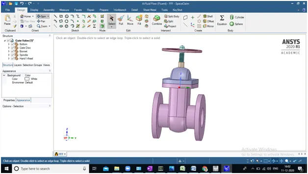
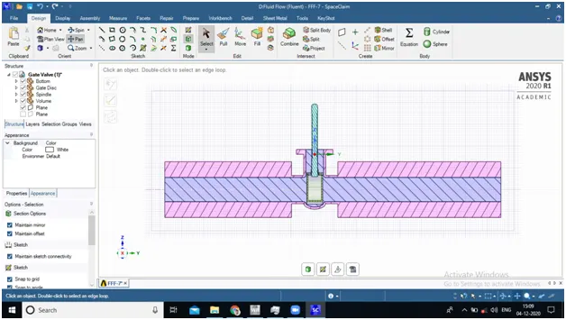
PROCEDURE :
Mainly following four parts included.
1). Pre-procesing
2). Meshing.
3). Solving .
4). Post- processing
1). Pre-processing : It's include preparation of geometry which is being use in our simulation part
- Remove (delete) unnecessary parts from geometry like hand wheel and bonnet
- Extend pipe towards inlet and outlet both by 500 mm and 650 mm respectively to insure complete hydro dynamically boundary develop
- Extract fluid volume and load geometry to meshing part .
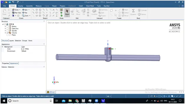
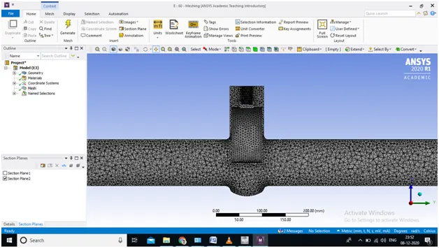
2). Meshing
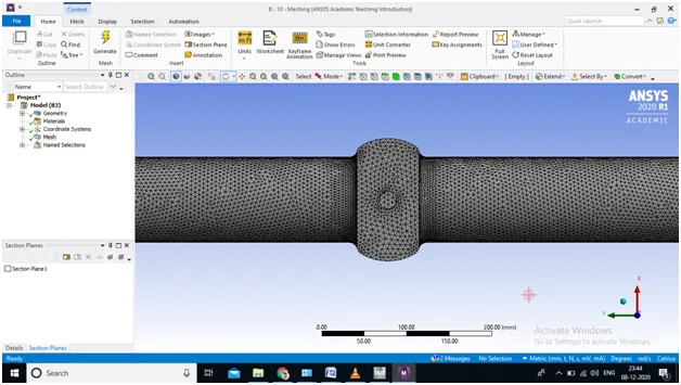
- Mesh Size : 5 mm
- Mesh Type : Tetrahedron
- Mesh quality : 0.83 (avg.)
- No. of element : 377871 (For all cases)
3). Solving :
- Select k-e , Realizable with Enhance wall Treatment Turbulence model
- Select Pressure based solver Transient time solution and unable gravity option and provide -9.81 m/s^2.
- Select pressure based solver and perform steady state simulation
- Add Water material from fluent database
- Boundary conditions:
- Inlet : 10 pascal pressure inlet type
- Outlet : 0 guage pressure
- Intialize solution as a standard
- Provide no. of iteration and calculate
- Boundary conditions:
4). Post- processing
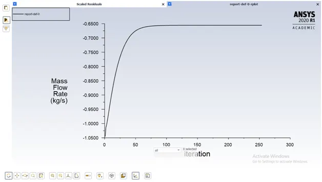
- Get plot of mass flow rate at outlet through definition
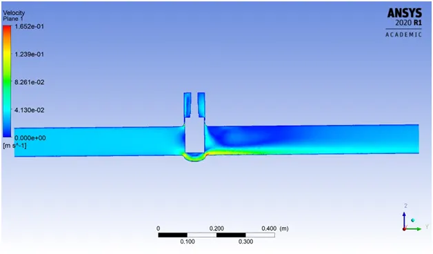
- Plot countour of velocity and create animations.
DIFFERENT CASES
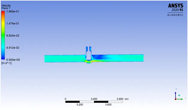
CASE -1 : OPENING VALVE DICS TO 10 MM
CASE -2 : OPENING VALVE DICS TO 20 MM
CASE -3 : OPENING VALVE DICS TO 40 MM
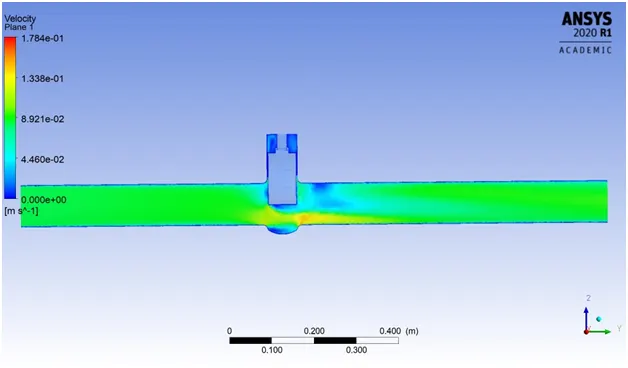
CASE -4 : OPENING VALVE DICS TO 60 MM
CASE -1 : OPENING VALVE DICS TO 10 MM
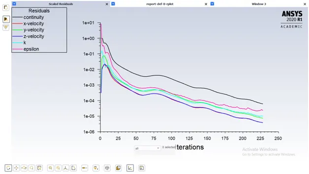
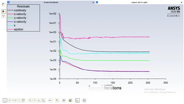
Residual plot
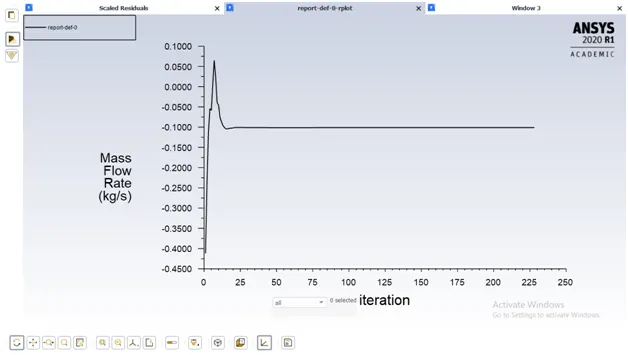
Mass flow rate variation plot
Velocity contour plot

CASE -2 : OPENING VALVE DICS TO 20 MM
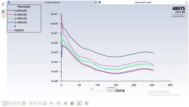
Residual plot
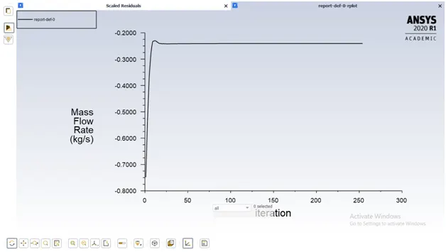
Mass flow rate variation plot
Velocity contour plot
CASE -3 : OPENING VALVE DICS TO 40 MM
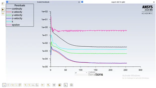
Residual plot
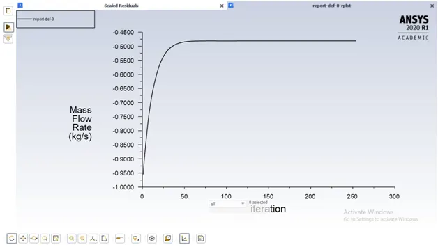
Mass flow rate variation plot
Velocity contour plot
CASE -4 : OPENING VALVE DICS TO 60 MM
Residual plot
Mass flow rate variation plot
Velocity contour plot
Parametric study in Ansys Fluent
Ansys fluent provides nice features of parameter set in output and input which save computational time solving all cases once rather than run and changes in cases separately every time
Here in our case gate valve disk lift provide as input parameter while in output mass flow rate selected as output parameter set
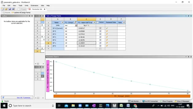
Provide input parameter as per requirement and check retain parameter and click update all data points
Valve Flow Coefficient (Cv) is a valve’s capacity for a liquid or gas to flow through it. It is technically defined as “the volume of water at 60°F (in US gallons) that will flow through a valve per minute with a pressure drop of 1 psi across the valve.
The often equated Cv value is the US measurement unit, which is given in USG/min (US-Gallon per minute), and can therefore not be compared with the Kv factor. Conversion formulas exist for these values:

- Kv = 0.857 * Cv
- Cv = 1.165 * Kv
- Importance of cv
- Quickly compare different brands of valves and their flow capacities
- Help to select a valve that is the right size (and not oversized) for the application
- Quickly understand how the valve you select will have an effect on the pressure in your system
Conclusion
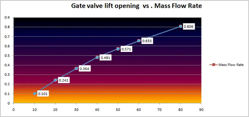
- All Residual plot & Mass flow rate at outlet plot converged well since there is fluctuation found in quantity.
- With Increses lift disc flow rate increses increses since more area available to flow in given pressure gradient of pipe.
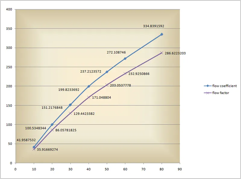
- Flow Coefficient of valve & Flow factor increse linearly (Approx.) as the Lift of gate valve increses.
- Since in our case Pressure gradient is constant Cv is only depend on the mass flow rate .