Week 3 Sheet metal Bending challenge
Sheetmetal Bending Challenge Report
Aim: Sheet metal bending is to be performed for 3 different materials mentioned below. Variation of certain settings is also to be performed and your conclusions are to be added to the report
Run the analysis for the material:
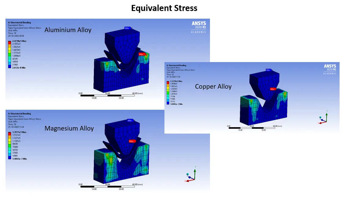
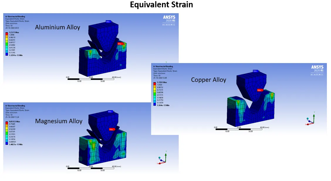
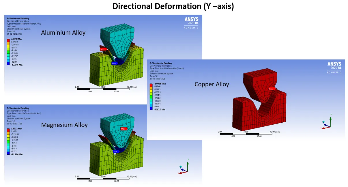
Case 1: Aluminium Alloy 1199(mentioned in the course video), Copper Alloy NL and Magnesium Alloy NL. Find out the Equivalent stress, Equivalent elastic strain and Total Deformation in Y direction and compare the results for the three materials.
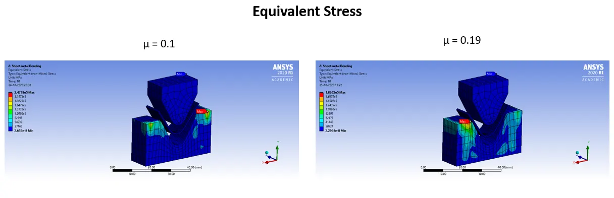
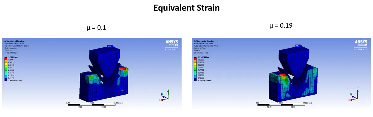
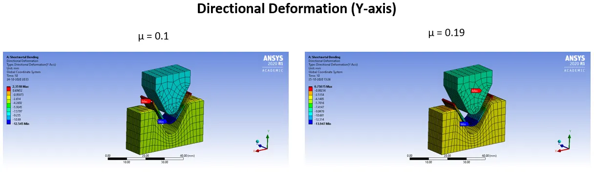
Case 2: With the material as Aluminium Alloy, change the friction coefficient to 0.19 and run the analysis as mentioned in Case 1. Compare the results with that in case 1.
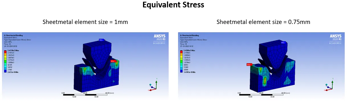
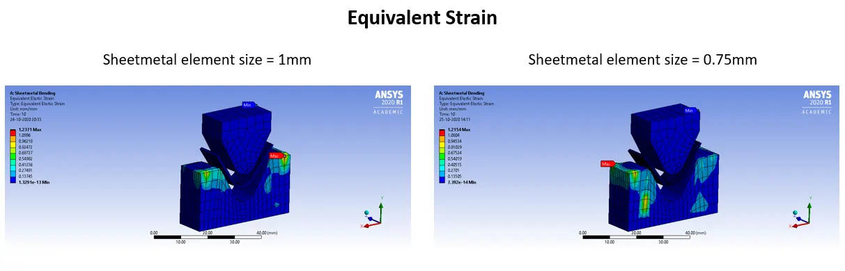
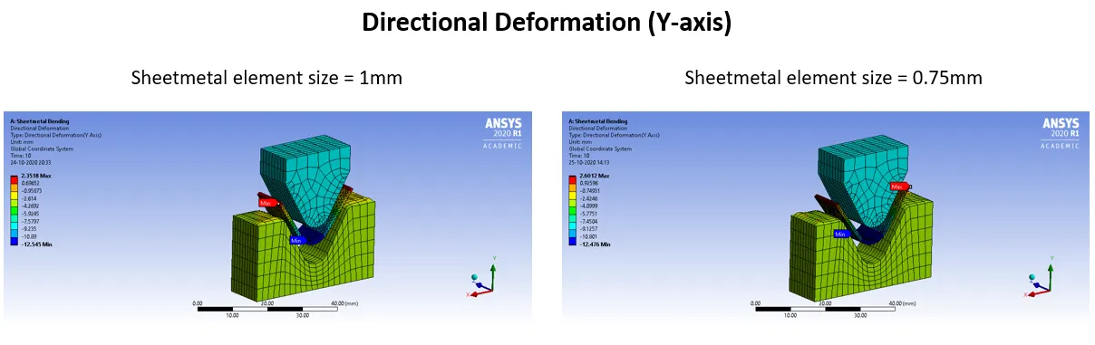
Case 3: Refine the mesh on the plate such that it doesn't cross the academic limit. With Aluminium alloy as material, run the analysis as in Case 1 and compare the results.
Submit the challenge as you would do in a proper project report with all relevant details such as settings, mesh size, images and tables included to provide your findings. Also, give an explanation as to which property/ properties of the materials affect the outcome.
Procedure:
- Select Static Structural, drag and drop into Project Schematic.
- Choose material as per requirement in all cases, under Engineering Data.
- Under geometry tab, import the given Sheetmetal punch and die geometry, double-click to open Space Claim to register the model.
- Then in Mechanical Module, assign a frictional connection between the punch & sheet metal as well as sheet metal & die with 0.1 coefficient of friction (case 1) and 0.19 in case 2.
- The punch and die were given a mesh sizing of 4mm.
- The sheet metal was given a mesh sizing of 1mm and tetrahedron mesh type was assigned. (case 1). In case 2, a mesh size of 0.75mm was given.
- Face sizing was also done to the punch and die contact surfaces. The mesh size was 1mm.
- Under static structural tab, we add Punch Displacement and enter the values of translational motion in 10 steps towards the sheet metal.
- The Die is fixed till the last two steps where it’s taken away from the sheet metal.
- The Sheetmetal is fixed firmly.
- Total Deformation in Y-axis, Equivalent Elastic Strain and Equivalent Stress plots are requested from the solver as outputs.
Case 1: Aluminium Alloy 1199(mentioned in the course video), Copper Alloy NL and Magnesium Alloy NL. Find out the Equivalent stress, Equivalent elastic strain and Total Deformation in Y direction and compare the results for the three materials.
Case 2: With the material as Aluminium Alloy, change the friction coefficient to 0.19 and run the analysis as mentioned in Case 1. Compare the results with that in case 1.
Case 3: Refine the mesh on the plate such that it doesn't cross the academic limit. With Aluminium alloy as material, run the analysis as in Case 1 and compare the results
Conclusion:
Case 1: This case can be summarized with the table below:
|
Sheetmetal Material |
Eq. Stress (N/mm2) |
Eq. Strain |
Deformation (Y -axis) (mm) |
|
Aluminium Alloy 1199 |
2.47E+05 |
1.2371 |
2.3518 |
|
Copper Alloy NL |
2.32E+05 |
1.1591 |
3.7046 |
|
Magnesium Alloy NL |
1.70E+05 |
0.85123 |
2.8532 |
We notice that the Stress and strain is maximum for Aluminium alloy 1199. The directional deformation is maximum for Copper Alloy. This could be because stress varies as per yield strength. Harder material will experience more stress.
Case 2: This case can be summarized with the table below:
|
Friction Co-efficient (µ) |
Eq. Stress (N/mm2) |
Eq. Strain |
Deformation (Y -axis) (mm) |
|
0.1 |
2.47E+05 |
1.2371 |
2.3518 |
|
0.19 |
1.87E+05 |
0.93474 |
0.75075 |
It can be noticed that by increasing the frictional co-efficient there is a positive change on all 3 parameters. The stress, strain and directional deformation all reduce.
Case 3: This case can be summarized with the table below:
|
Sheetmetal Mesh Element Size (mm) |
Eq. Stress (N/mm2) |
Eq. Strain |
Deformation (Y -axis) (mm) |
|
1 |
2.47E+05 |
1.2371 |
2.3518 |
|
0.75 |
2.43E+05 |
1.2154 |
2.6012 |
Here we can observe the validation of grid dependency test. By reducing the element size to 0.75mm from 1mm we are able to achieve a more accurate result for all 3 parameters (stress, strain and directional deformation)