Week 3 - External flow simulation over an Ahmed body.
EXTERNAL FLOW SIMULATION OVER AN AHMED BODY
Objective
- To simulate external flow over an ahmed body
Theory
Ahmed body
- Ahmed body is a 3D research model that represents a standard passenger car, It is developed to verify the CFD code (turbulence models).
- Physically Ahmed's body is built and a lot of experimental analysis is done on the body, hence one can get a lot of experimental data to verify their CFD code.
Negative wake pressure and point of separation
- When fluid flows over a body, It exerts drag and lifts forces on the body due to boundary layer formation, viscous shear, and pressure.
- And one key concept to keep in mind is, as the fluid converges area decreases, flow accelerates, kinetic energy increases, pressure decreases.
- Similarly, as the fluid diverges, area increases, flow deaccelerates, kinetic energy decreases, pressure increases.
- And In converging flow Pressure gradient (dP/dx is negative) is favorable to the flow direction, In diverging flow pressure gradient is positive and it is not favorable to the flow direction
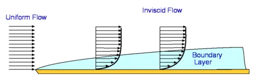
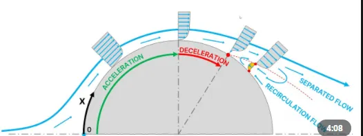
- The above Fig shows the boundary layer formation over a flat plate, but generally, the thickness of the boundary layer increases in the flow direction.
- When a flowing fluid encounters a surface normal to the flow, At that point flow stops, velocity becomes zero and pressure reaches the maximum value, this point is a stagnation point
- Near the stagnation point, flow follows the surface of the body due to boundary layer formation, And flow is converging and hence fluid accelerates.
- As the fluid flows along the surface of the body, the boundary layer thickness increases due to which flow area increases, flow decelerates, pressure increases ( In short we can say fluid is diverging)
- Due to which pressure gradient becomes positive along the flow direction, Hence fluid layer near the surface reverse its flow direction at this point flow is said to be separated (point of separation)
- After complete detachment of fluid from the surface, fluid diverges and hence the high-pressure region is created beyond the body creating a wake region.
- In the wake region, due to high-pressure fluid layers starting to recirculate in the direction opposite to the actual flow direction. since this pressure is not favorable to the flow direction it also increases the drag, and flow velocity almost becomes zero.
Modeling And Setup
Space claim
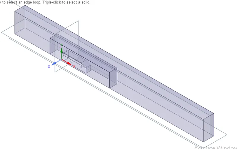
- Use "Enclosure" option is used to develop a computational domain around the Ahmed body to create external flow over the body.
- Local refinement is done around an Ahmed body to capture the flow behavior near the body and wake region.
- For local refinement, another small volume is added around an Ahmed body using the enclosure option.
- And the model is checked for Interference to avoid overlapping of two computational volumes around the Ahmed body, it ensures the smooth exchange of information between the two computational volumes (to happen: share topology option must be set to 'share').
- In SpaceClaim, the 'Enclosure' recognizes the larger and smaller bodies and subtracts the smaller body volume present in the larger body.
- The split body command is used to split the symmetric Ahmed body to simulate since it reduces the mesh numbers. and it does not affect the simulation soluttion.
Mesh
- Hexahedral mesh has the highest quality among all the types of mesh.
- outer body: method: multizone : element size 100: max size 100mm
- Multizone generates the hexahedral meshes wherever possible and smoothly forms connections between the different types of meshes present in the region.
- Inner body: sizing
- Ahmed body: cylinder support faces: sizing:10mm
- boundary layer mesh: for wall boundary conditions the mesh cell center should be nearer to boundary : in order to achieve that we have to refine the mesh near the wall by adding inflation layers
- wall: inflation at named selection: select wall: inflation is first layer thickness ( calculated using reynolds number and yplus condition)
- To capture boundary layer Y+ of 5 is considered to get the first cell height of 0.00007235 meter.
- GRID DEPENDENCY
| LEVEL | TYPE OF MESH AND SIZE | Number Of Elements | Remarks |
| Base |
|
1,22,980 | 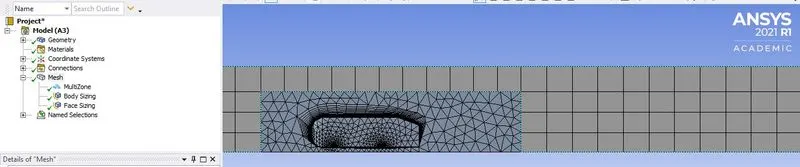 |
| Fine |
|
1,78,089 | 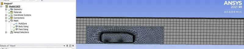 |
| Very Fine |
|
2,51,316 | 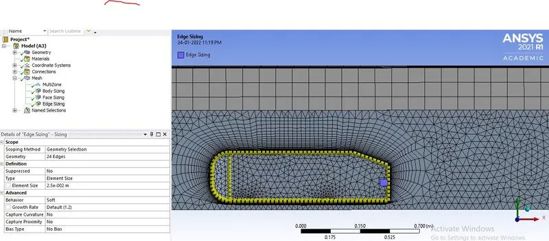 |
| Extremely Fine |
|
4,77,636 | 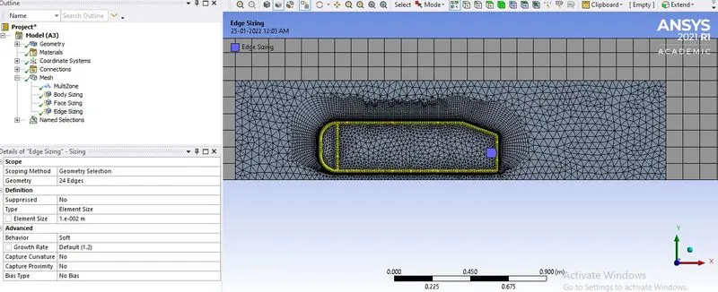 |
Solution Setup
- Pressure based steady flow solver, K omega sst turbulent model is used
- Fluid material: Air with desnsity 1.225kg/m3 and dynamic viscosity 0.000017894 kg/ msec
- Boundary conditions: inlet: 25m/sec : outlet: gauge pressure : 0
- The hybrid solver uses a potential flow solver, (stream function and velocity potential variables satisfy continuity equation), it is used to get the fair initial conditions.
- Convergence is unchecked, and simulation ran for 300 iterations.
RESULT
GRID DEPENDENCY:
| LEVEL | DRAG | %Diff=Drag | LIFT | %Diff=Lift |
| Base | 12 | - | 6.25 | -- |
| Fine | 11.25 | 6.66% | 7.5 | 16.66% |
| Very Fine | 10 | 12.5% | 8 | 6.25% |
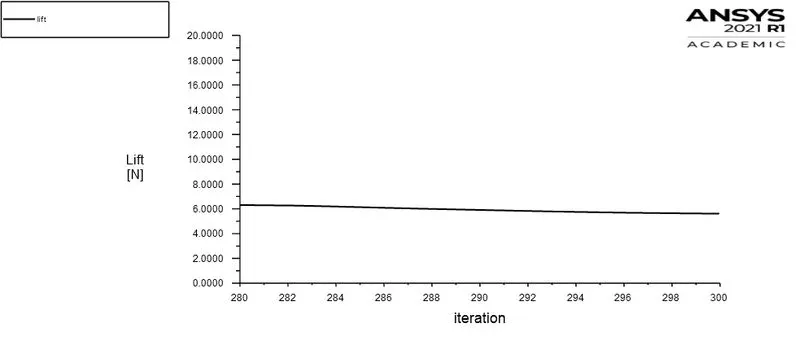
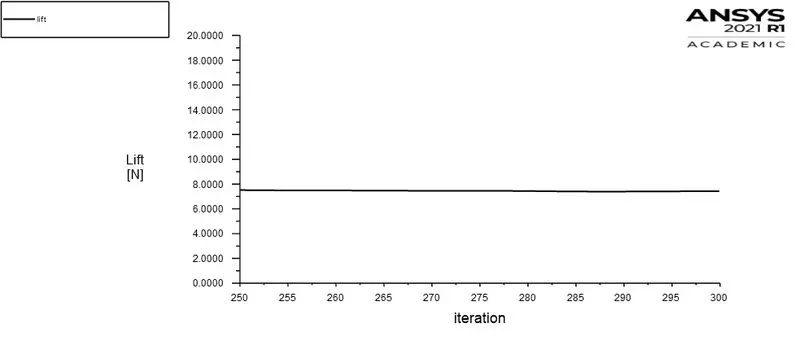
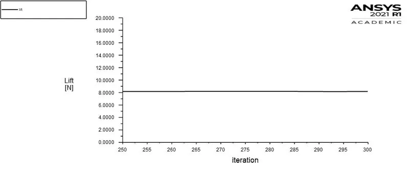
| Extremely Fine | 9.75 | 2.56% | 8 | 0 |
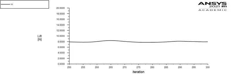
- From the above result we can say,the solution is almost becoming grid-independent but not able to conclude due to student version limitation.
- Hence we are considering the extremely fine mesh condition to explain the simulation result.
- And also at extremely fine mesh, solution is more refined.
| LEVEL | DRAG | VELOCITY | PRESSURE | LIFT |
| BASE | 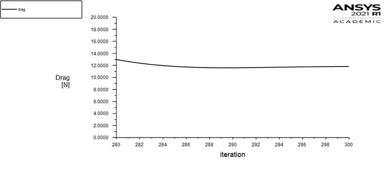 |
 |
 |
 |
| FINE | 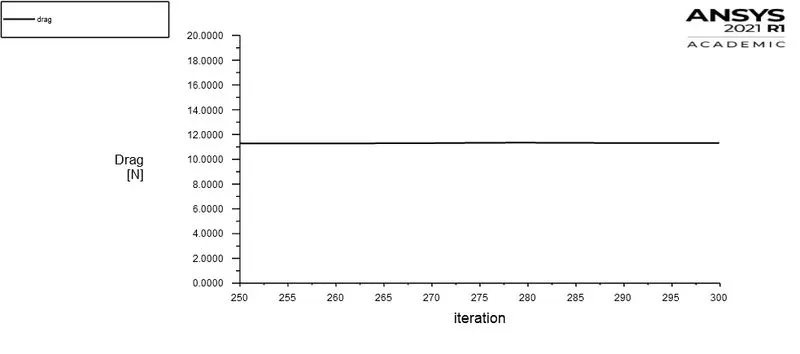 |
 |
 |
 |
| VERY FINE | 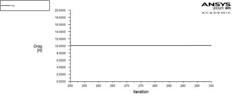 |
 |
 |
 |
| EXTREMELY FINE | 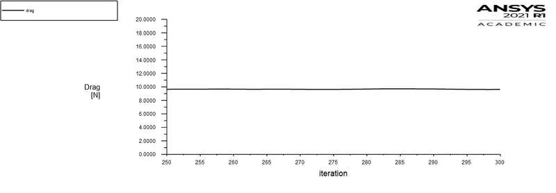 |
 |
 |
 |
Flow over ahmed body
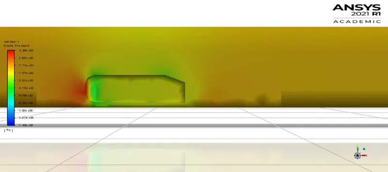
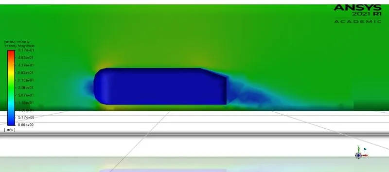
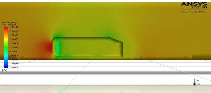
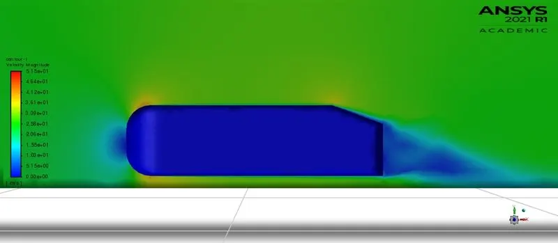
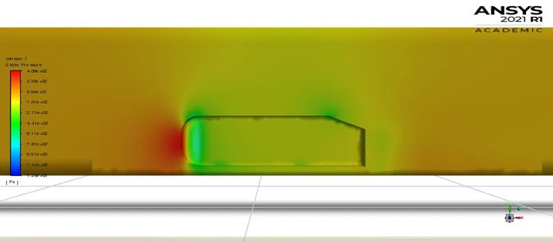
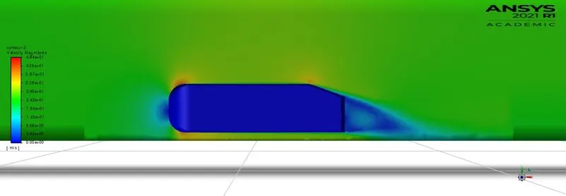
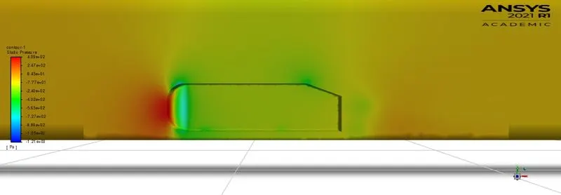
- From the velocity and pressure contur plot we can see that velocity is zero and pressure is maximum at the front (at center) portion of the ahmed body indicating the satagnation point.
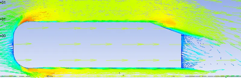
- And also Wake region can be seen where velocity is almost zero and recirculation of fluid layers can be seen from the vector plot.
- The red regions near the wall in velocity plot indicating the accelerating flow and blue regions indicating decelerating of the flow in the boundary layer
- From the drah graph, we can say 9.75 is the drag force and projected area is calculated from the ansys solver is 0.065741 meter2
- If we calculate Cd using this formula
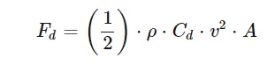 , we get 0.38 as the drag coeffecient
 |
|
|
Thank you