MBD Simulation on IC Engine Valve Train
MULTI BODY DYNAMICS SIMULATION OF IC ENGINE VALVE TRAIN
AIM:
- Run the motion analysis of the IC engine valve train using Solidworks for cam lift 3.5mm and 6mm.
- To obtain valve lift and contact forces between
- Cam and Push Rod
- Pushrod and Rocker Arm
- Rocker Arm and Valve
THEORY:
- A valve train is an assembly that controls the timing of intake and exhaust valves opening and closing in an IC engine at very high precision.
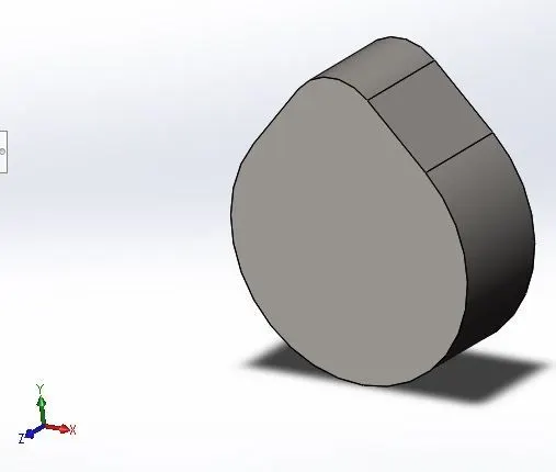
- Cam is a rotating link in the mechanism which transforms the rotary motion into straight-line motion due to its unique shape. Usually, it is an integral part of the camshaft and it is referred to as cam lobes, these lobes are placed and oriented on the camshaft in a unique fashion, to get the required valve timing.
- Cam is connected to push rod through a higher pair and it is force closed by the force due to rocker arm and spring.
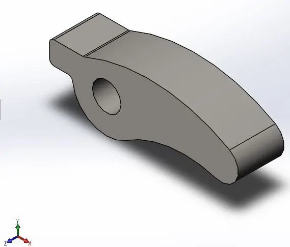
- rocker arm which transmits the linear motion of the pushrod into the linear motion of the valve.
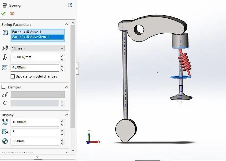
- A spring is attached to the valve, which helps in the retreat of the valve and also keeping the pushrod in place. Because during rotation of cam at high speed, pushrod may lose contact with cam due to inertia.
- The distance by which the valve is moved is called valve lift, this valve lift depends on the 'cam lift' and 'spring force'.
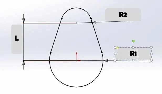
- Cam lift formula is given by
- R1 = radius of lower circle
- R2 = radius of upper circle
- L = Distance between two centers
- Cam lift = (L-R1)+R2
MODELLING AND SIMULATION:
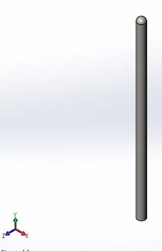
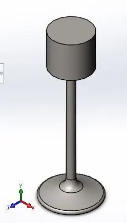
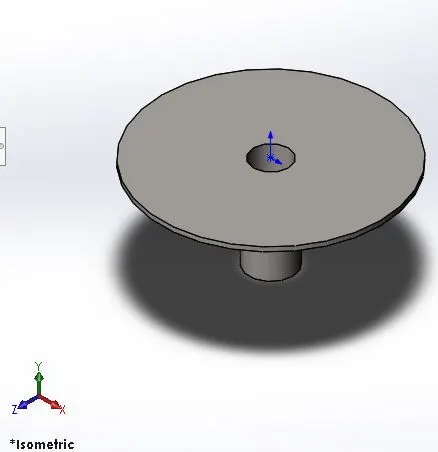
- 3D models of the cam, pushrod, rockerarm, vale train and valve seat is done according to the drawing.
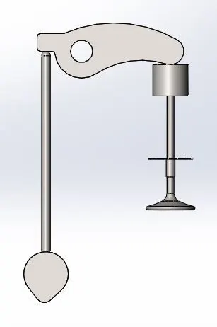
- And assembly is done and assembly mates are provided such that constrained motion is obtained between the parts(links).
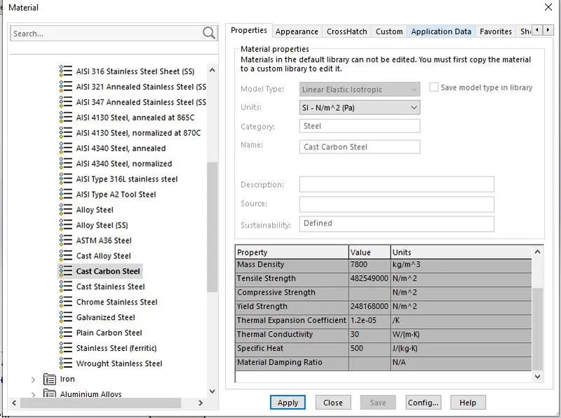
- Before motion Anlysis ,Cast carbon steel assigned as material for all the parts.
- In motion anlysis, input rotary motion (1500 rpm )is given to cam, contacts between the links are established without selecting the material.
- In motion analysis settings, '9000 frames per second' was selected with 'precise contact' option is enabled to get results at every degree of rotation.
- Spring is intoduced on the valve seat with spring constant(25 N/mm), pretensioned to 10 mm and simulation ran for 2 seconds.
3D parts
Assembly
Material Properties
Motion Analysis
RESULT
For Cam lift = 3.5 mm
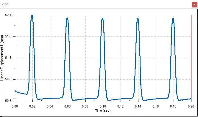
- Valve lift at spring force 25 N/mm
- Valve lift of almost 2 mm is observed form 50.3mm to 52.4mm.
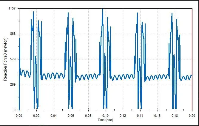
- Contact Force between Cam and push rod
- Force is exerted by cam on the push rod, and peak value observed at the starting and ending of cam lift.
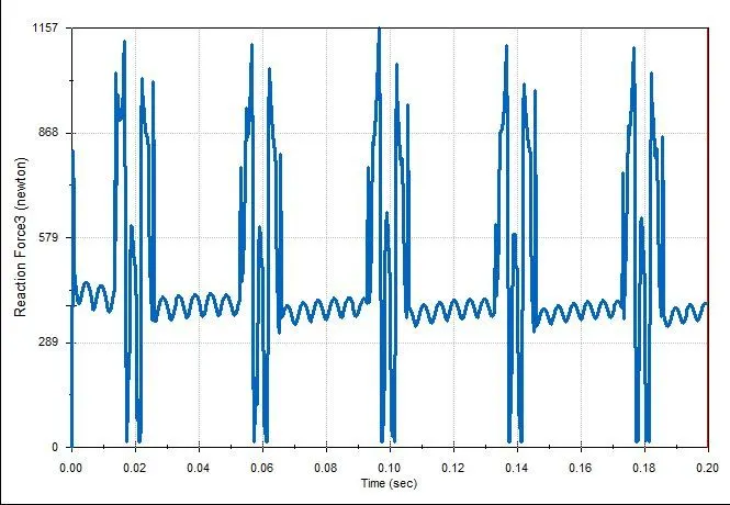
- Contact Force between push rod and Rocker arm
- Force is exerted by Push rod on the rocker arm, and peak value observed at the starting and ending of cam lift.
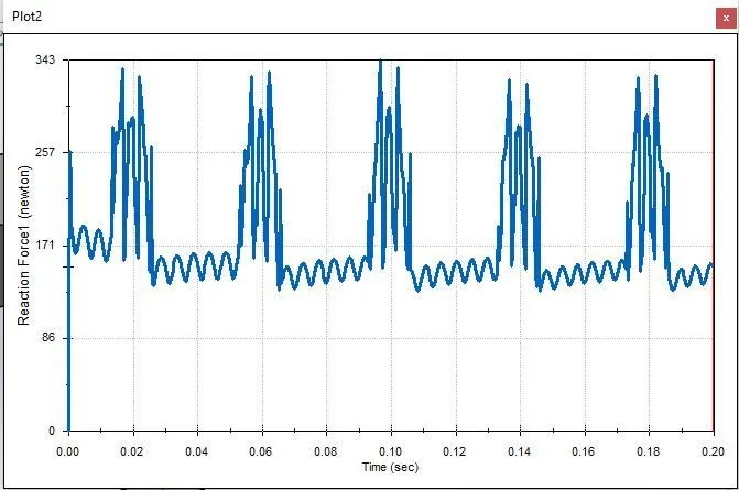
- Contact Force between Rocker arm and valve
- Force is exerted by Rocker arm on the valve (connected with spring), and peak value observed at the starting and ending of valve movements.
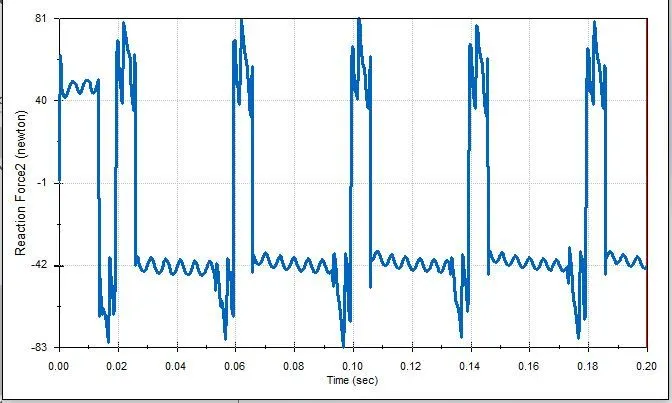
- Contact Force between Rocker arm and valve in x direction
- friction force is exerted by valve on the sliding of rocker arm.
- Peak value observed when rocker arm pushes the valve in normal direction, since friction force is directly proportional to normal force.
For Cam lift = 6 mm
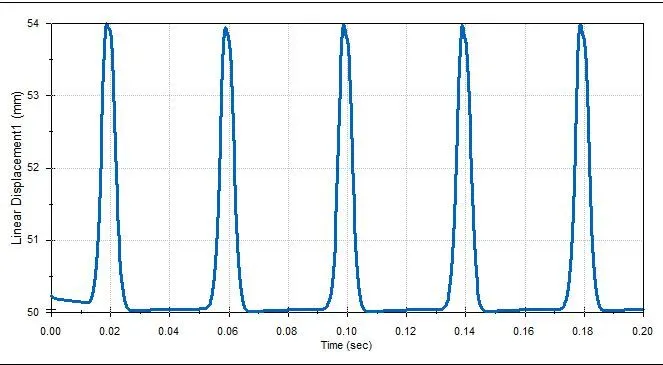
- Valve lift at spring force 25 N/mm
- Valve lift of almost 4 mm is observed form 50mm to 54mm.
- Contact Force between Cam and push rod
- Force is exerted by cam on the push rod, and peak value observed at the starting and ending of cam lift.
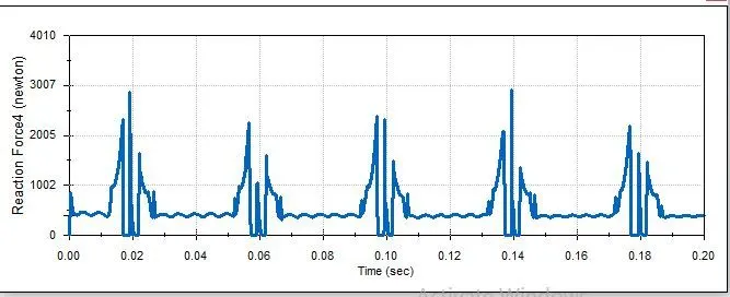
- Contact Force between push rod and Rocker arm
- Force is exerted by Push rod on the rocker arm, and peak value observed at the starting and ending of cam lift.
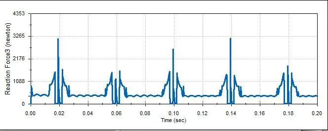
- Contact Force between Rocker arm and valve
- Force is exerted by Rocker arm on the valve (connected with spring), and peak value observed at the starting and ending of valve movements.
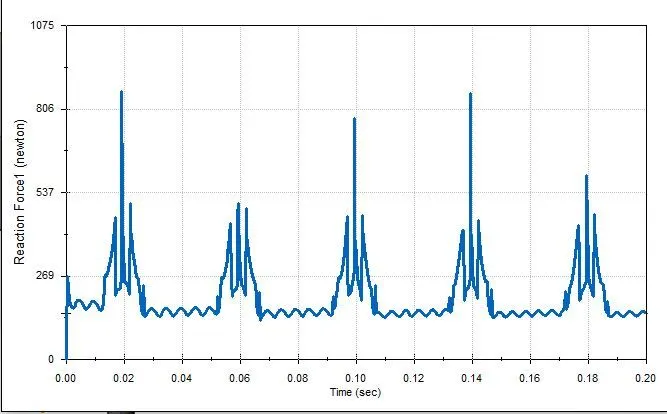
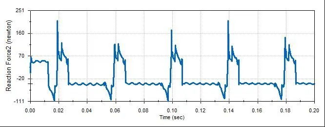
- Contact Force between Rocker arm and valve in x direction
- friction force is exerted by valve on the sliding of rocker arm.
- Peak value observed when rocker arm pushes the valve in normal direction, since friction force is directly proportional to normal force.
THANK YOU