Flow over an airfoil
FLOW OVER AIRFOIL
AIM: To simulate airflow over Airfoil NACA0017 with Angle of attack 0,2,4,6,8, and 10 using SOLIDWORKS.
THEORY:
- Airfoil is a streamline shaped body designed to produce Aerodynamic force
- This aerodynamic force can be resolved into two components, one is drag force and another one is the lift force
- The force developed in the direction of flow is drag force and force which developed perpendicular to the direction of flow is lift
- These forces are arises due to the formation of the boundary layer, viscous force, and pressure difference.
- In an airfoil, what happens is fluid flow is obstructed by the leading edge of the airfoil, the flow gets separated and starts to converge along the streamlined surface of the airfoil and the boundary layer gets separated at nearly at the trailing edge.
- Generally, the velocity of flow over the top surface of the airfoil is high with low pressure and at the bottom surface velocity of flow is low with high pressure, this pressure difference creates a lift force, this principle used to fly the aircraft.
- The angle of attack is the angle between the fluid flow direction and airfoil chord line (straight line joining leading and trailing edge), as it varies fluid separation along the streamlined surface of airfoil also varies and hence drag and lift forces also varies.
- The airfoil of NACA4series, NACA0017 means describes an airfoil with a camber of 0 chord located at 0 chord with 0.17chord of maximum thickness.
- Camber means asymmetric between the top and the bottom surface of the airfoil since it is zero NACA0017 is a symmetric airfoil, Asymmetric airfoil can produce more lift at zero angles of attack compared to symmetric
SIMULATION STEPS
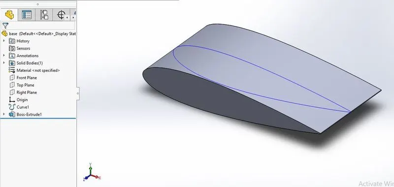
- NACA0017 airfoil datafile is generated to get coordinates of the airfoil curve, using this datafile airfoil curve is created, the curve is rotated to get the angle of attack 0,2,4,6,8, and 10 and extruded to 50m.
- In flow simulation wizard, simulation name (eg:4AOA angle of attack 4), time-dependent external flow, Air as flowing fluid and velocity 600m/s in x-direction is specified
- 2D Computational domain is selected and length (at front 5times the length and at rear 10 times the length) and height (5 times the length at both side) of the domain is increased.
- Using Goal command, Force along x (drag) and Force along y (lift) is specified along the streamlined body of the airfoil to calculates its value.
- XY plots are specified to visualize the preesure and velocity profile
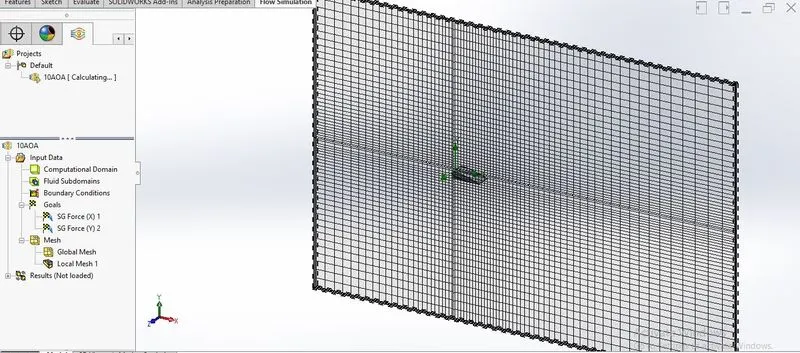
- The basic mesh is generated and local mesh is introduced to refine the mesh along the streamline body of the airfoil
- Simulation was run to get the results.
- Using origin software, Lift and drag plots were obtained.
RESULT
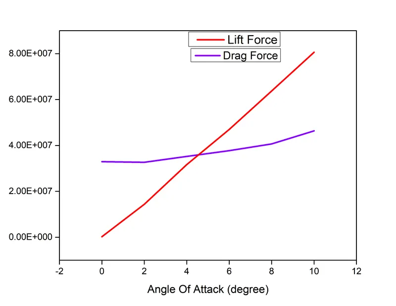
- Drag and lift force values are calculated
- These values are plotted as a function of angle of attack to compare the results
- From the plot, it is concluded that as the angle of attack increases lift force increases linearly by large amount, while drag force is increased in small values.
Velocity profile
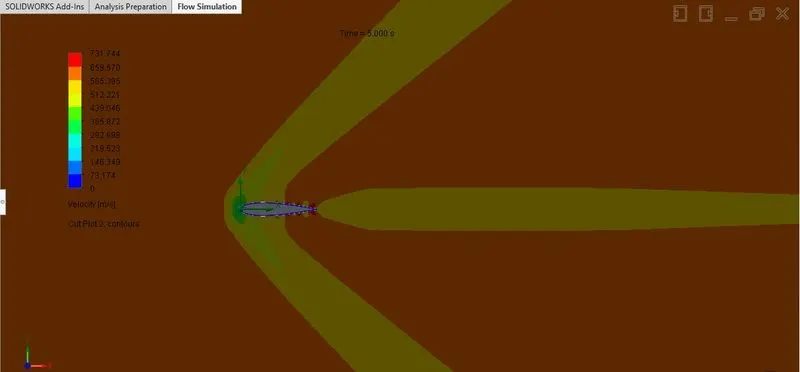
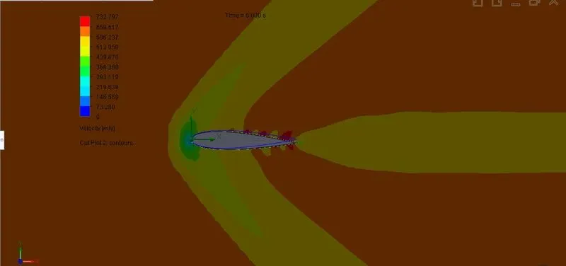
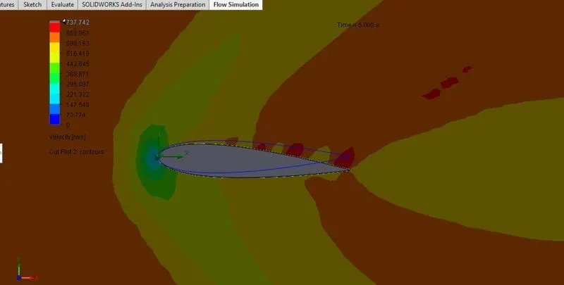
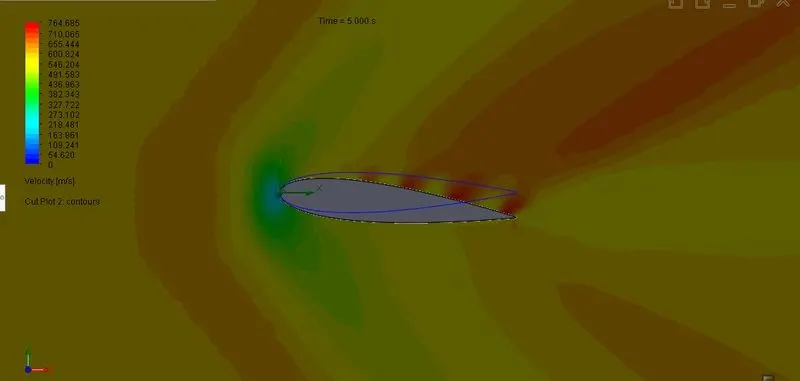
- From the velocity profile, we can visualize that as the angle of attack increases, velocity over the top surface of the fluid is also increasing
- At the entry of the airfoil, fluid stagnation point (i.e zero velocity) can be observed.
@ angle of attack "0"degree
@ angle of attack "2"degree
@ angle of attack "4"degree
@ angle of attack "6"degree
@ angle of attack "8"degree
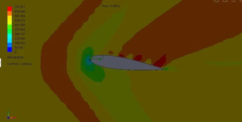
@ angle of attack "10"degree
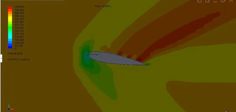
Pressure profile
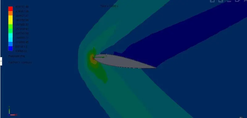
- From the pressure profile, we can visualize that as the angle of attack increases, pressure over the bottom surface of the fluid is also increases.
- At the stagnation point, the maximum value of pressure can be observed
@ angle of attack "0"degree
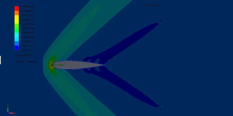
@ angle of attack "2"degree
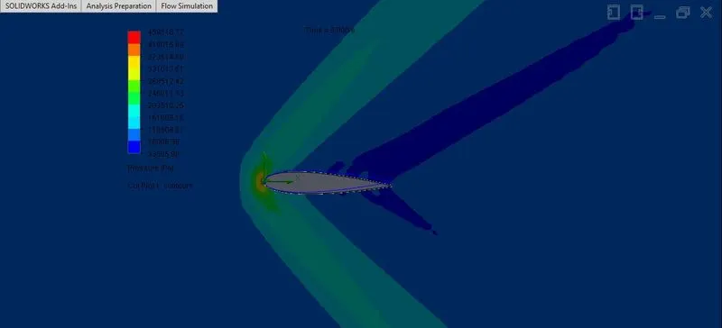
@ angle of attack "4"degree
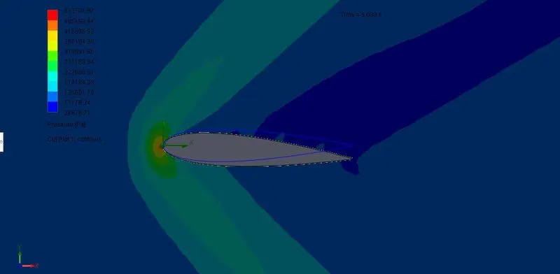
@ angle of attack "6"degree
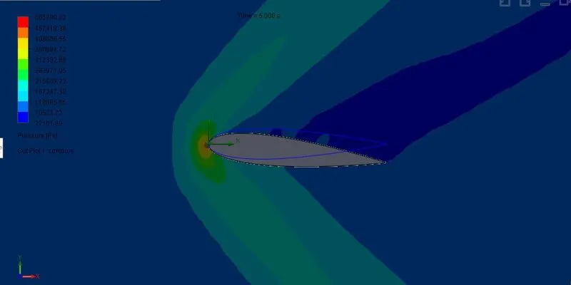
@ angle of attack "8"degree
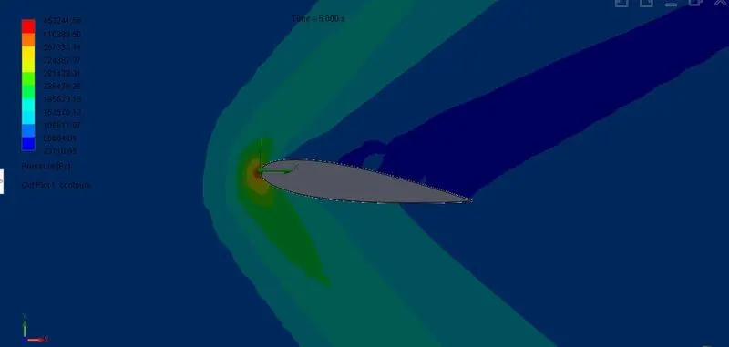
@ angle of attack "10"degree
Thank you