Centrifugal pump design and analysis
DESIGN AND ANALYSIS OF CENTRIFUGAL PUMP
Aim: To create a 3D model of centrifugal pump and obtaining a performance curve of the pump through CFD simulation using SOLIDWORKS
Introduction:
- A Centrifugal pump is a mechanical device, which converts the low energy head of fluid to a higher energy head with the help of a rotating impeller
- Usually, the impeller of the pump is driven with the help of an electric motor
- Rotating the impeller sucks the fluid axially, due to rotation of the impeller it imparts the centrifugal force on the fluid, which increases the energy head of the fluid, According to the requirement this energy head(pressure head, potential head, and kinetic head) is utilized for various applications.
- Usually, the centrifugal pump has a volute casing, which has an increasing cross-section till the outlet, which converts the kinetic energy of the fluid into pressure energy thus reduces the frictional loss
- Generally all pumps as their own performance curve, according to that curve pump works.
- The performance curve is the "Head v/s Discharge" curve.
Design and analysis of Centrifugal Pump:
First Step
- In this project, a very rough design of centrifugal design for understanding.
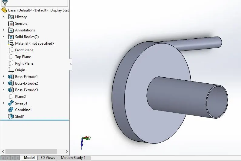
- Using sketch tools like a circle, circular pattern, trim tools, an impeller sketch is created and ir is extruded about midplane, similarly, casing( while extruding merge option is unchecked) and the inlet is also created.
- the outlet is obtained by creating a new plane and sweep pattern.
- Boolean operation 'ADD' is done to make inlet casing and outlet as one component.
- Shell tool is used to create a cavity
- Next, a control volume is created, that is used in the simulation to emulate the rotation of the impeller.
Second Step
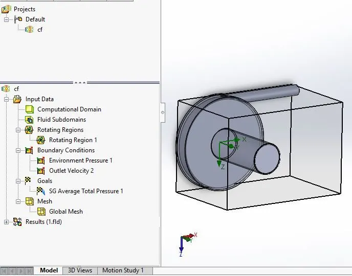
- For CFD simulation, Lids are created @ outlet and inlet
- Simulation inputs are internal, rotational, water (working fluid), standard temperature, and pressure.
- To emulate the rotation of the impeller, in the component selection of flow simulation control volume(extruded) is unchecked
- In rotating component, control volume(extruded) is selected and velocity value of 1000 rad/sec is given
- Boundary conditions of environmental preesure @ inlet (101325 Pa) and outlet velocity @ outlet (100 m/sec) for base line simulation
- The surface goal of the Average value of total pressure @ outlet
- Basic mesh with local refinement is done
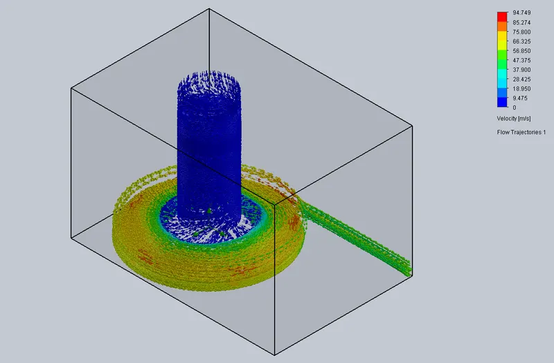
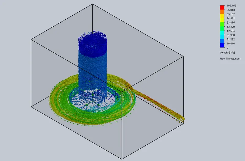
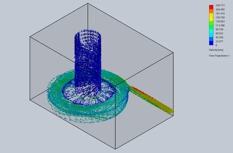
- As result, flow trajectories are created
- Before running the simulation, in the calculation control option, only the iteration option is checked for 500 iterations, to avoid early convergence of total pressure value
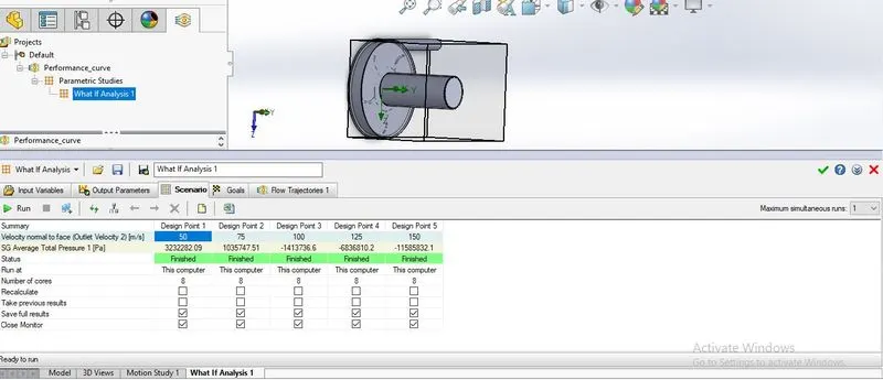
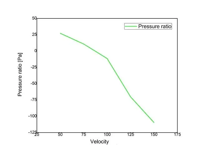
- After baseline simulation, a parametric study is done by only varying the outlet velocity (50, 75, 100, 125, 150 in m/s) and every other thing is kept as it is.
Result
- Flow trajectories and performance curve of the designed pump is obtained
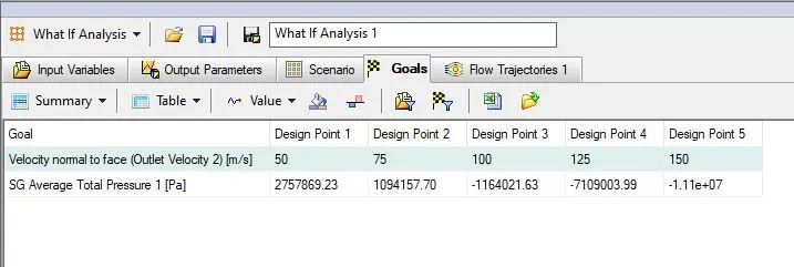
- From the performance curve, it can be seen as the discharge velocity increases pressure ratio decreases, which is theoretically correct.
- Hence the designed pump is theoretically correct, but from the practical point of view pressure value obtained is not correct(Since it is a made-up design).
- From flow trajectories, it can be seen that how water is sucked @ the eye of the impeller from the inlet, vortex motion of the water, and discharge @ outlet.
Performance Curve(Outlet pressure/Inlet pressure V/S Velocity) and Surface goal(Outlet Pressure)
Flow Trajectories
50m/sec
75m/sec
100m/sec
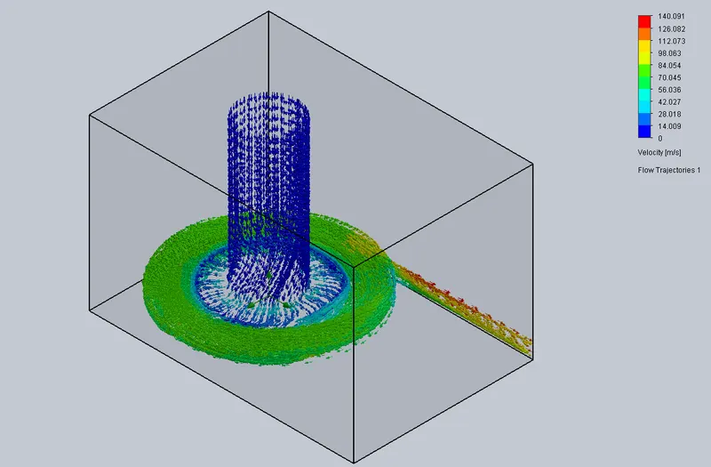
125m/sec
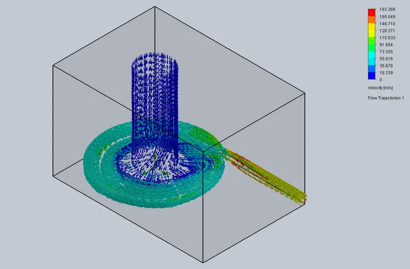
150m/sec
Thank You