SHELL MESH ON CAR HOOD
Week 3 challenge: Hood design
Aim:-
To understand the basic commands and getting familiar with Ansa GUI, while geometry clean up and meshing
Objective:-
- Understand command that needed for geometry clean-up
- Working with the commands to clean the geometry, while geometry checks
- Extracting mid surface for all the parts that need to mesh
- Rearranging and deleting the construction line which is required for mesh
- Forming a good mesh on the mid surface by satisfying the quality criteria
Procedure:-
Steps to be followed to mesh the part:
- Import the geometry into ansa
- Find the error in geometry by using checks
- Clean the geometry by using geometry cleanup tools in topo mode
- Then extract the mid surface to component and save it in different PID(property id), do geometry clean up for mid surface.
- After completing the checks the remove unwanted construction lines which may affect meshing
- Give the quality parameters and save it
- Then after giving mesh parameters by taking minimum and maximum length, the average length
- Then after start meshing the parts
Importing and geometry check
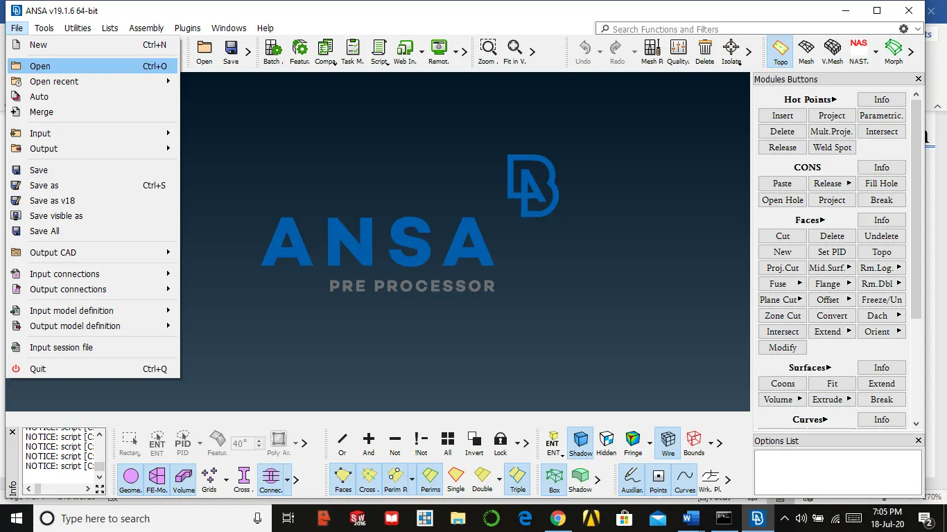
We need to import the model from drive to ansa by using
File →open → select file → ok
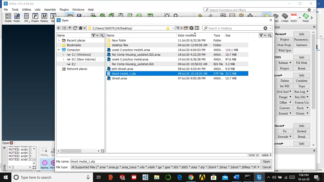
After importing then we must check geometry
Tools → check → geometry → all entities → run
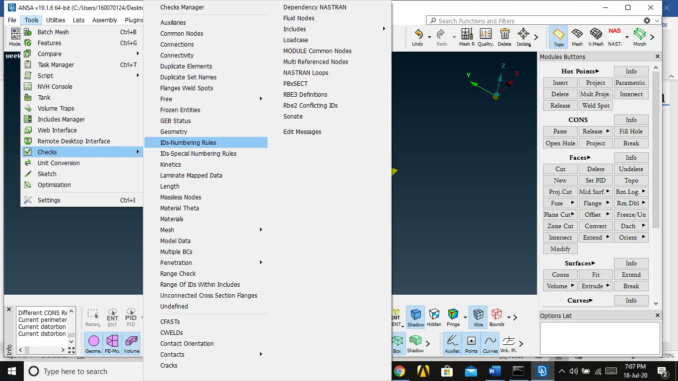
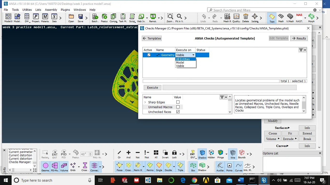
Then it will some errors, now close the window and select topo in faces, then select all entities and click the middle mouse button.
Then again check geometry maximum errors will be rectified, if anything else the select all the errors at a time and right-click mouse and select fix ansa try to clear error by itself
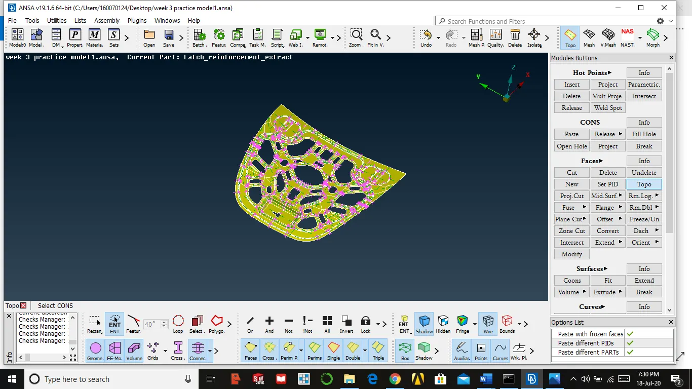
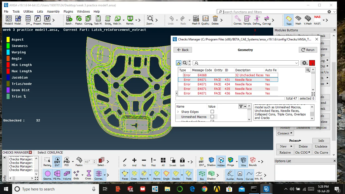
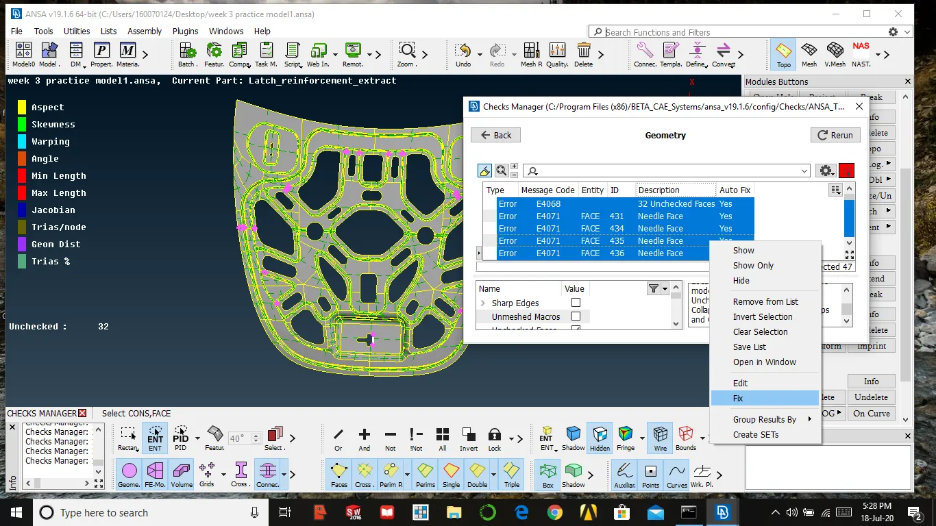
If any error is present then we need clear them by using options in coons like release, paste and other option like use topo in faces to join the cons
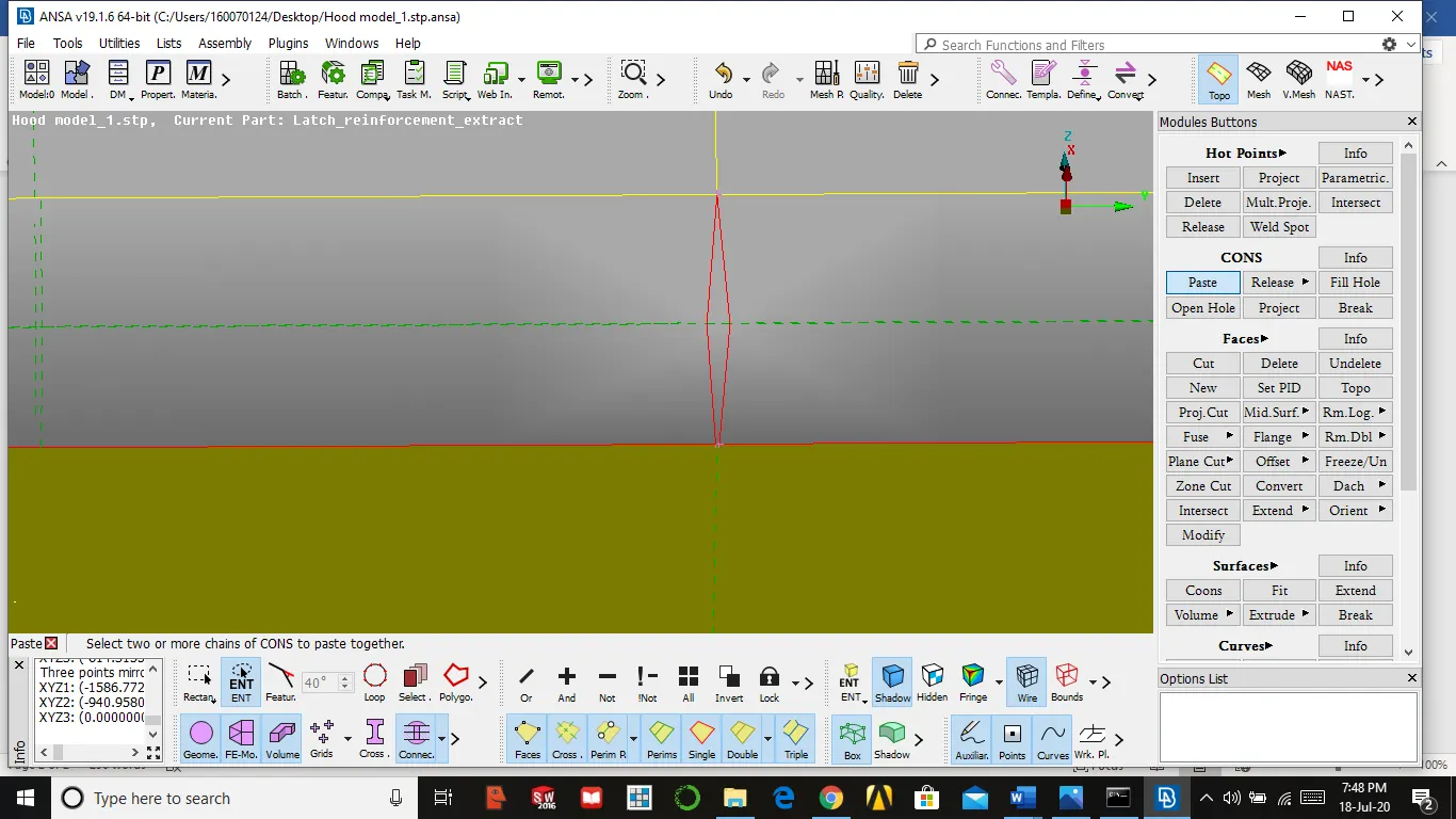
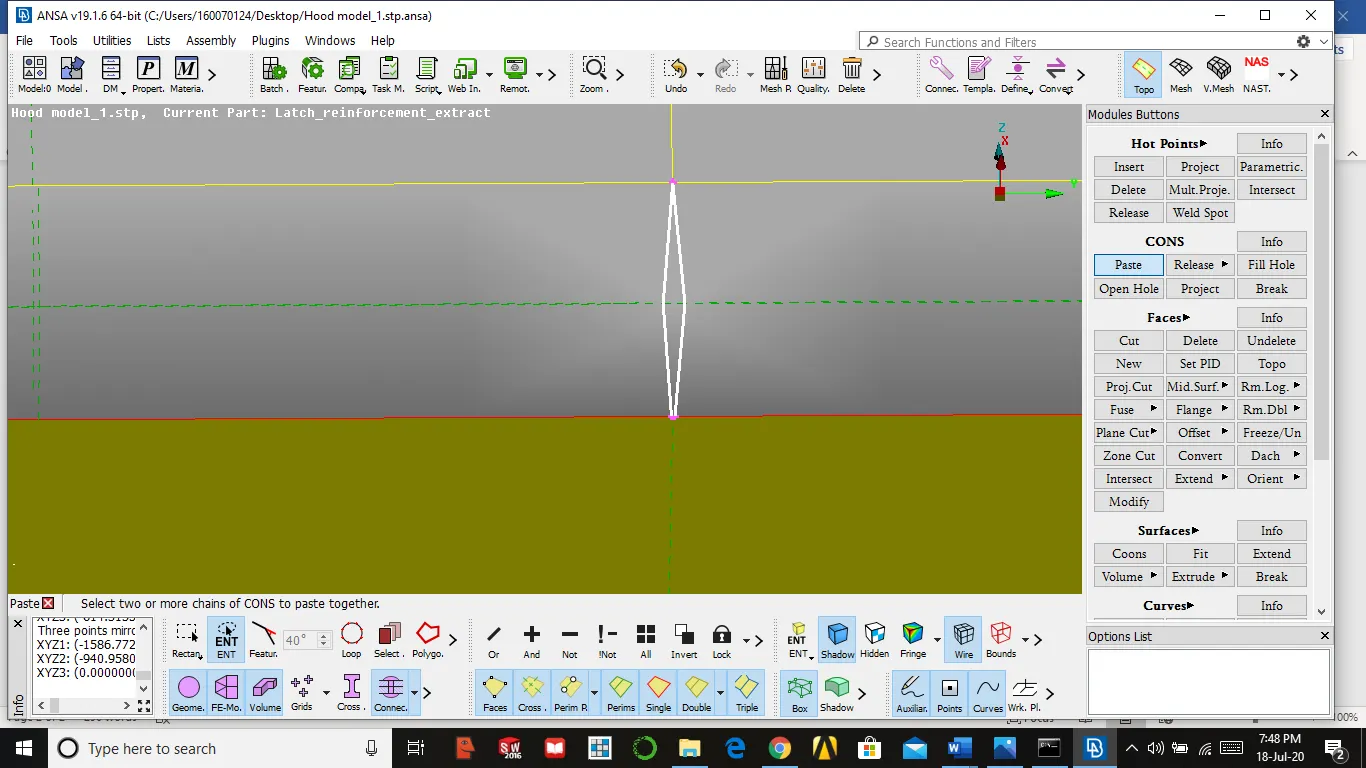
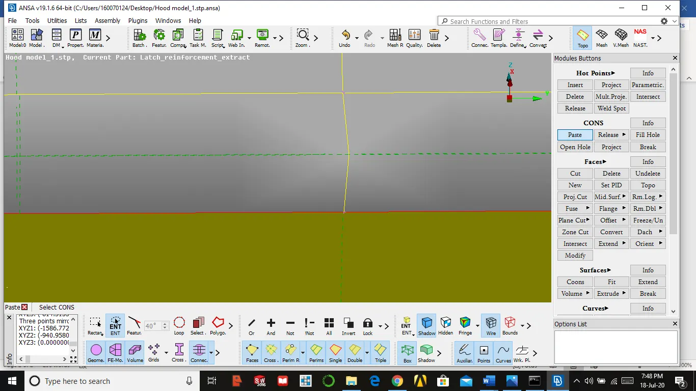
- If triple con occurs without having contact with three surfaces then we need to remove the surface by using delete in faces or more two surfaces sharing the same point will result in triple con, release it by using release in coons and select topo in faces and join them
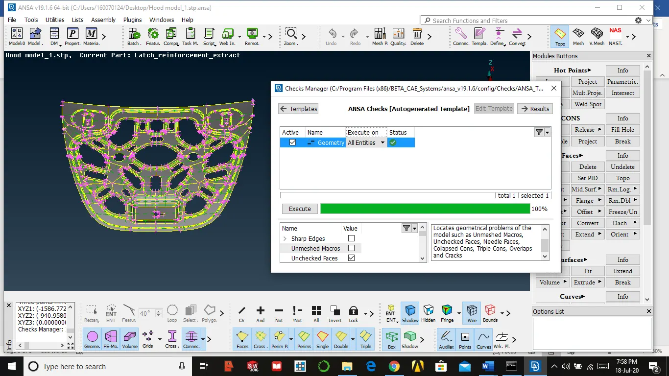
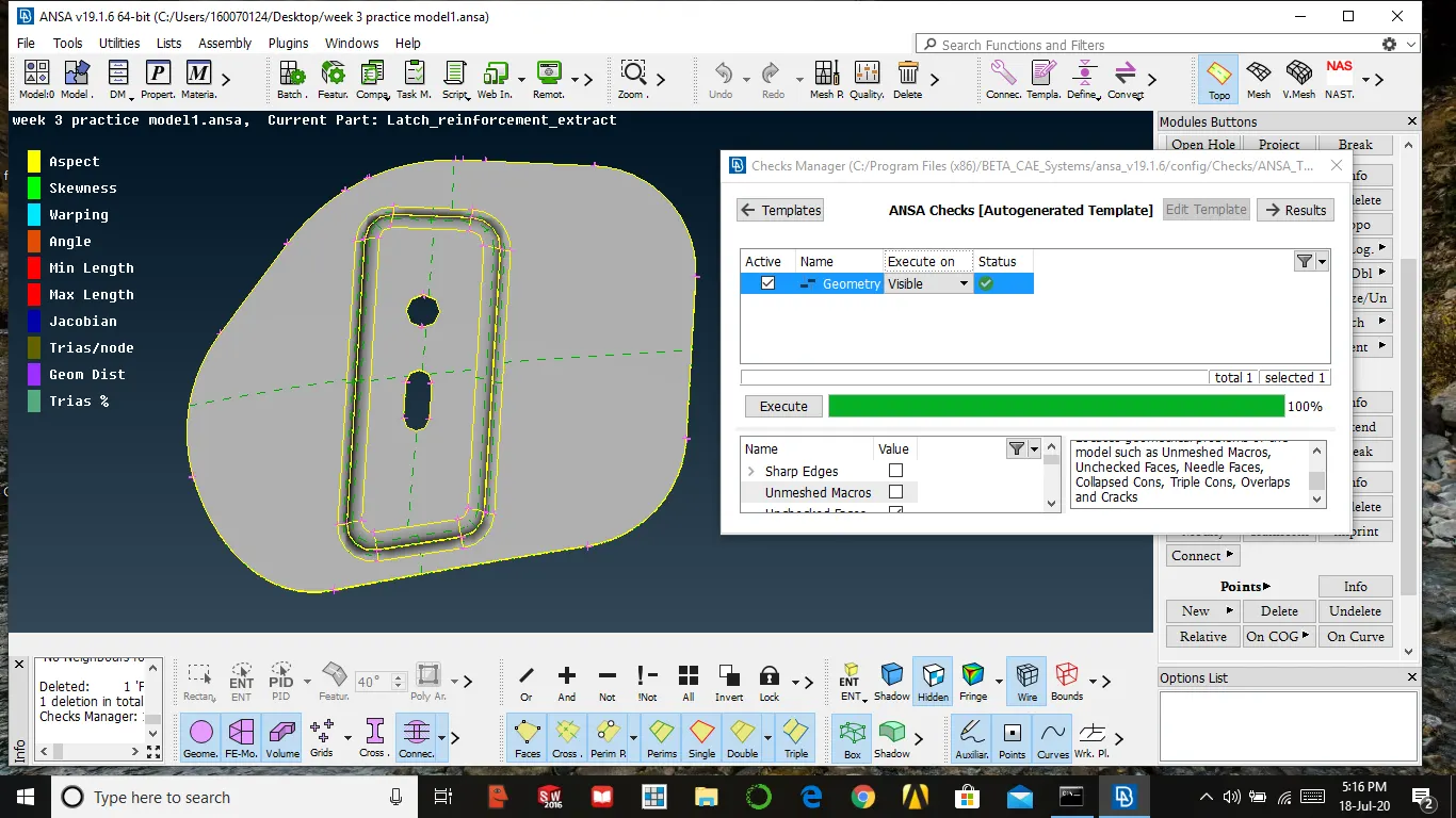
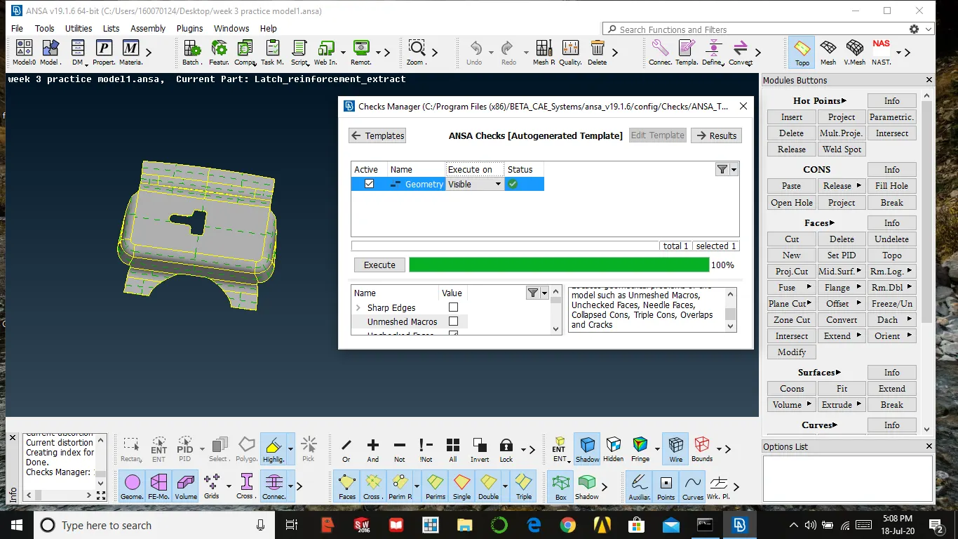
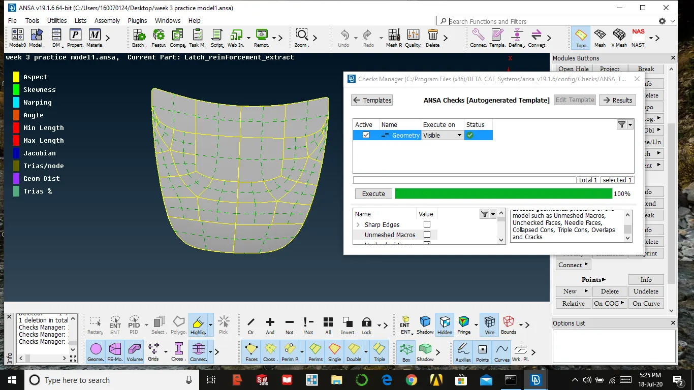
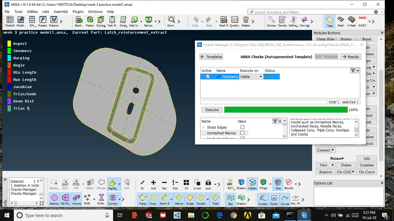
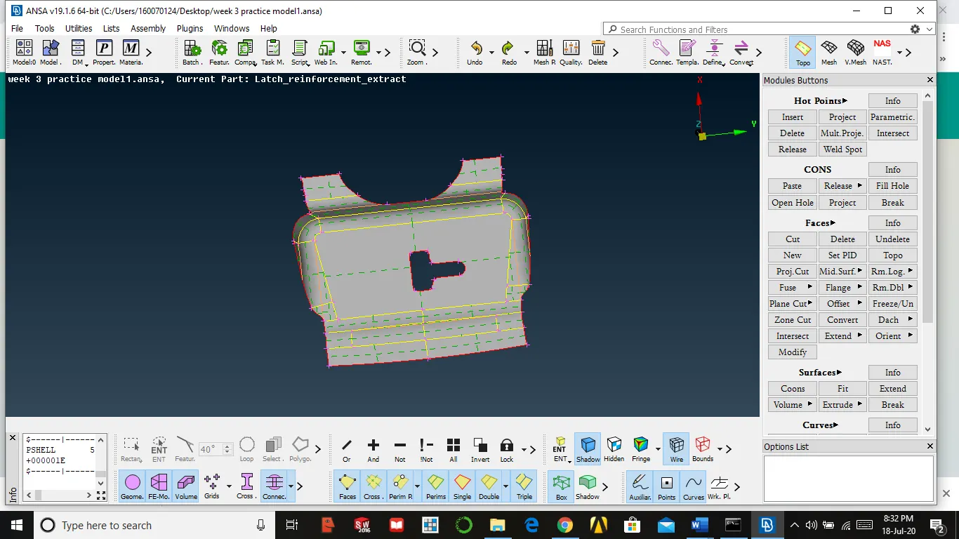
- After completion, the checks will give ok as the image is shown below
Extracting mid surface and setting it in different property
We can extract the mid surface by various methods like auto mid surface, offset, middle .these options come under face only we use any of them
Steps need to follow for extracting mid surface
- We need to measure the thickness and store the values
- Then after we need to use offset in faces by giving half the value of the thickness
- Select one layer either top or bottom by using the feature as a sub-option because it helps to select the entire surface at a time, by varying its angle
- Then select ok and make sure that do not select delete the faces
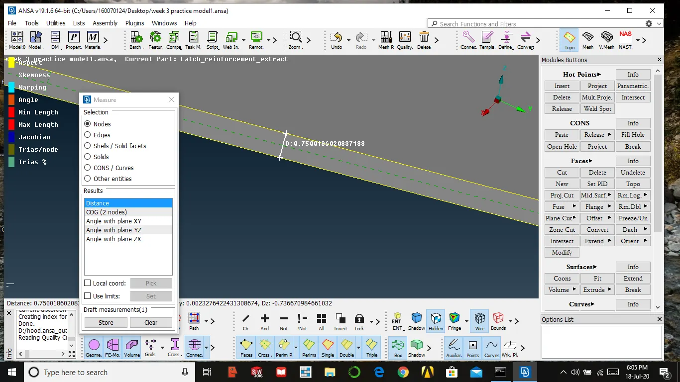
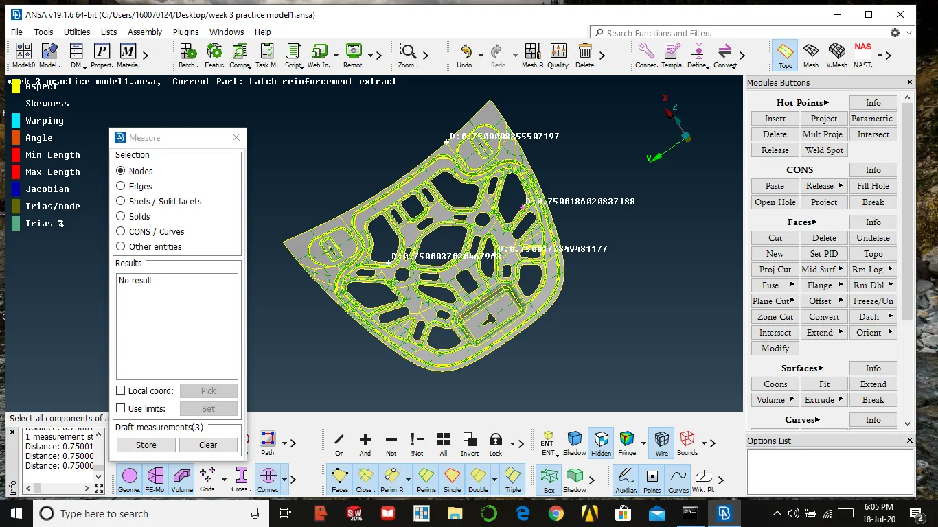
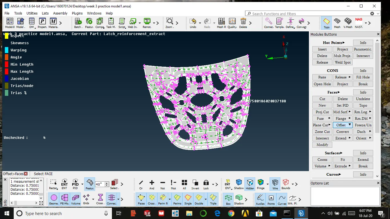
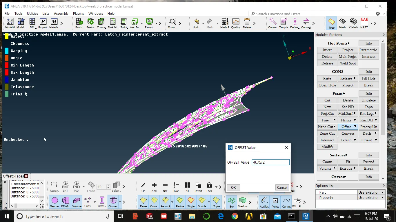
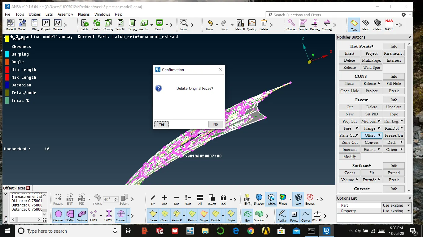
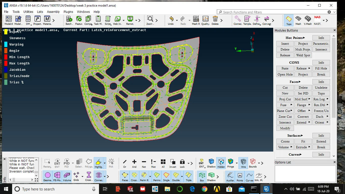
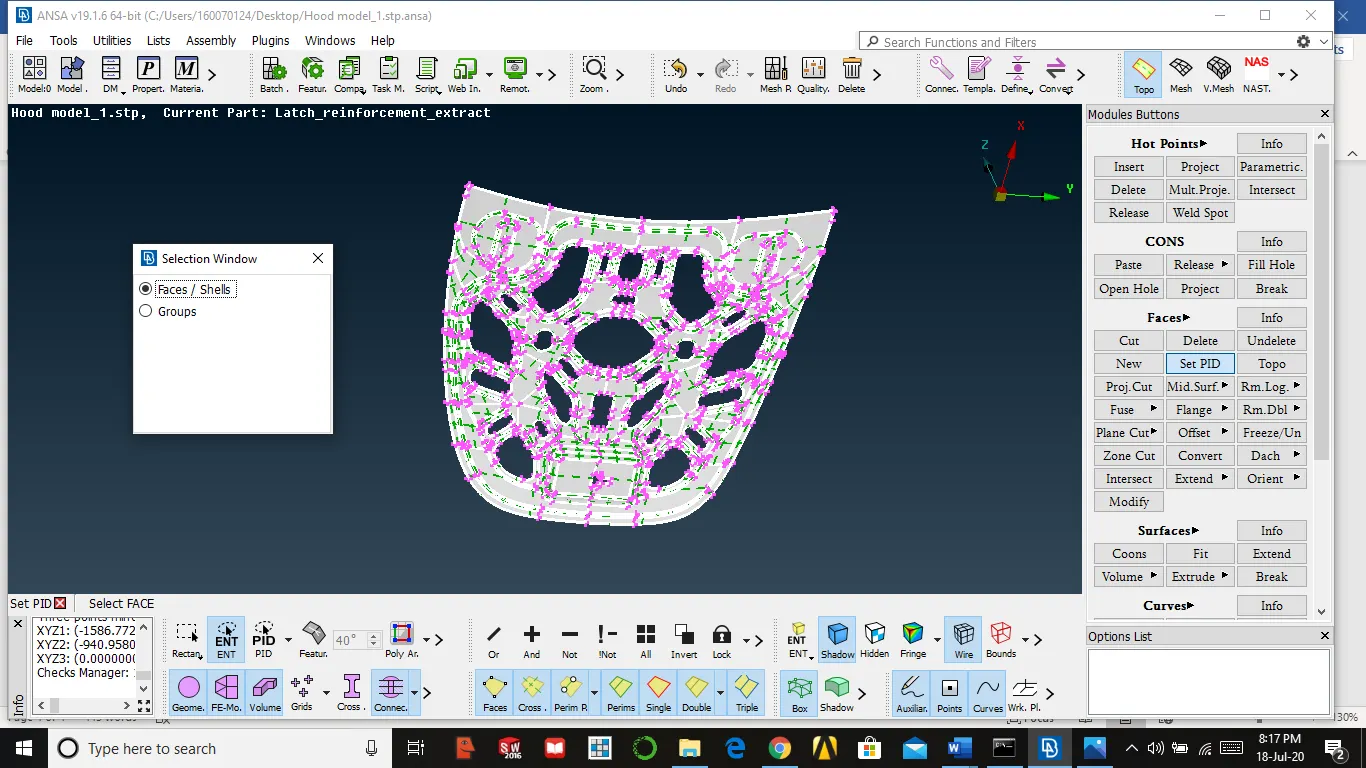
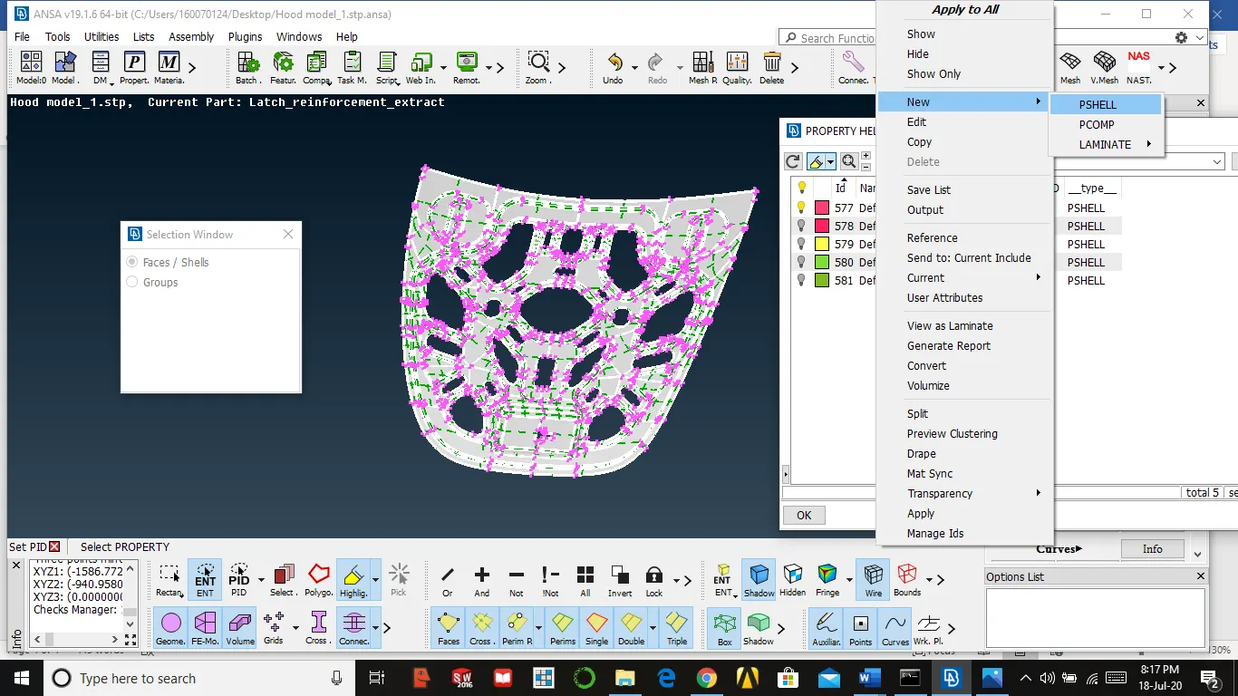
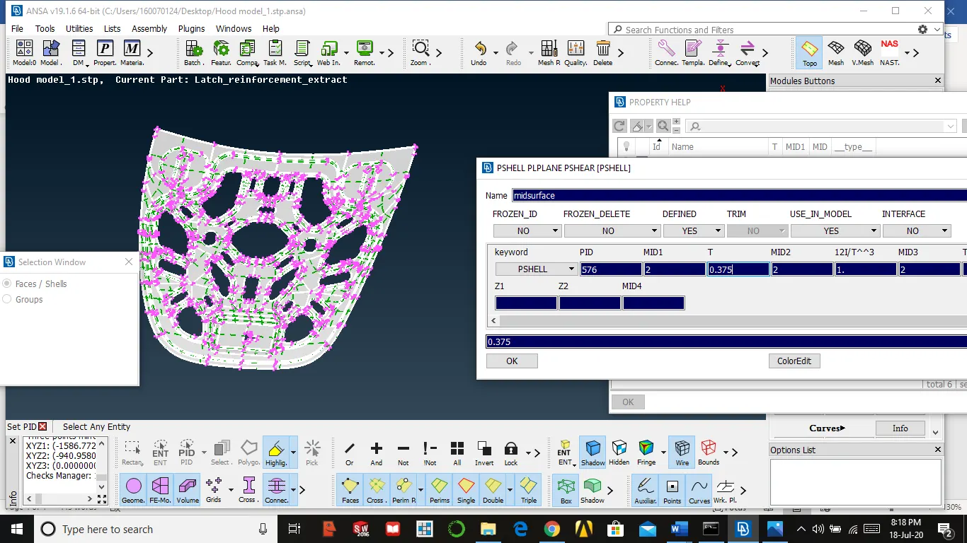
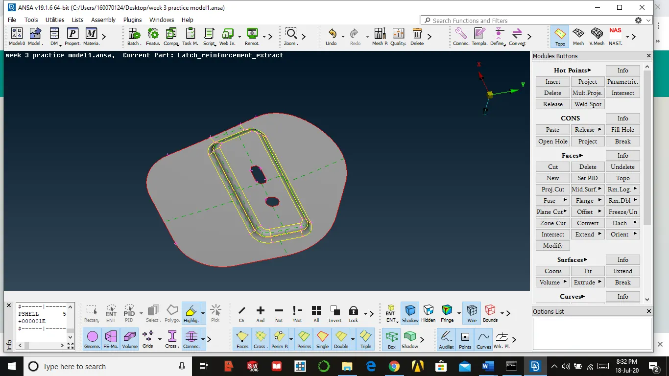
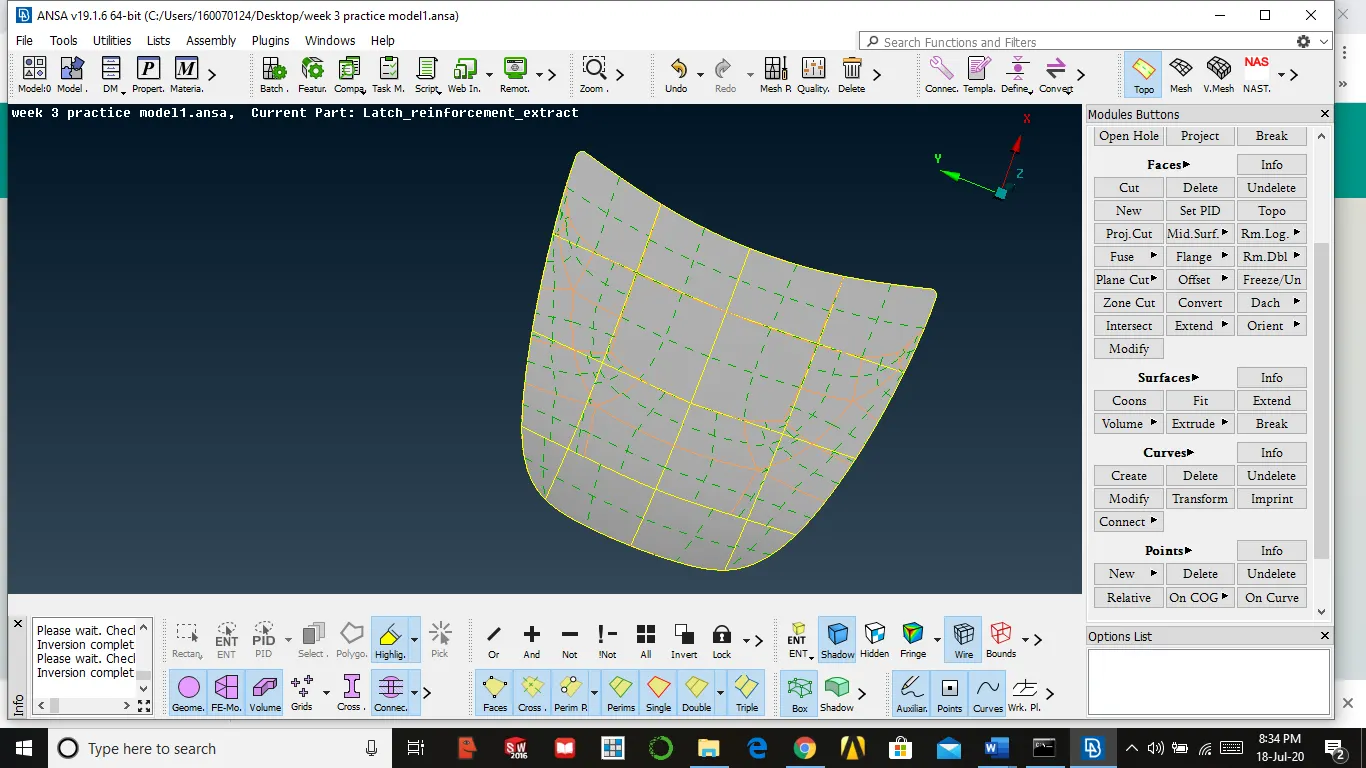
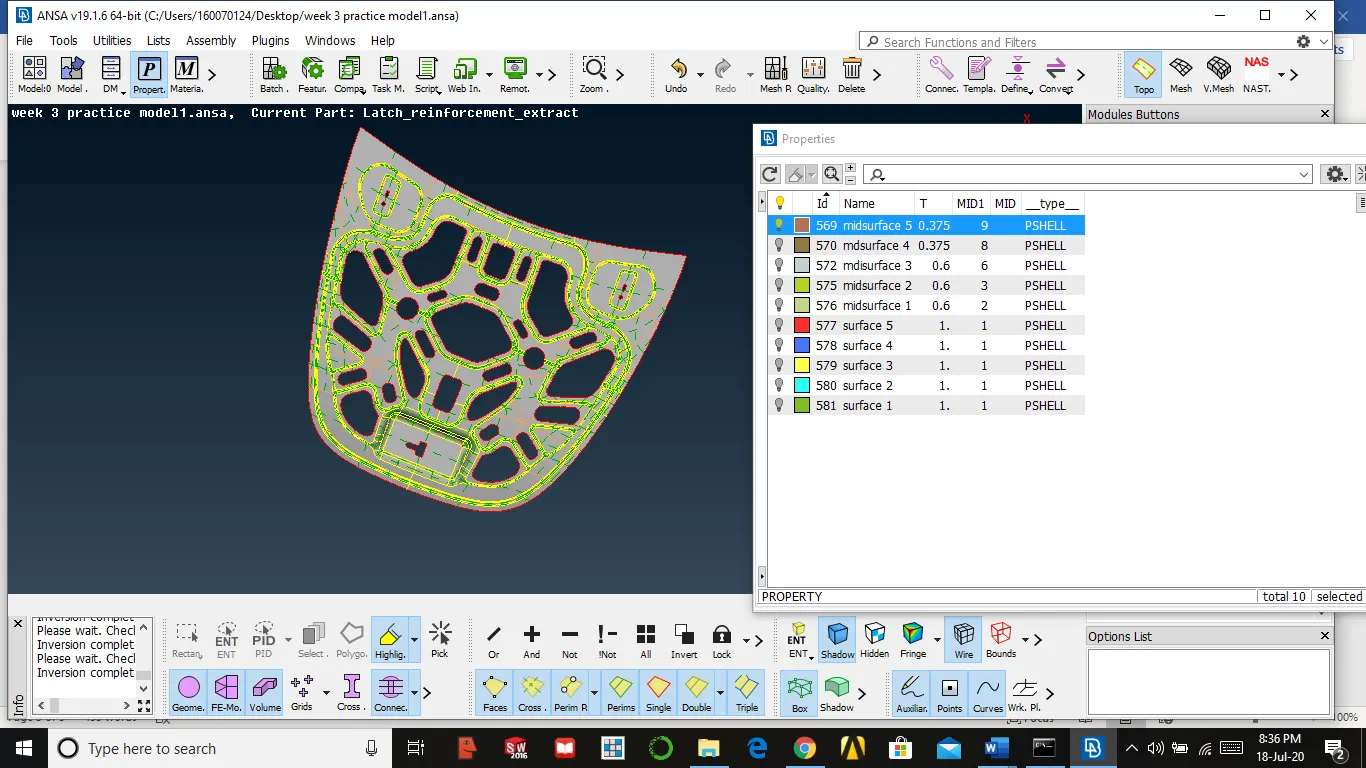
All parts mid surface extracted and saved in different PID, After that, we need to check geometry again and clean up
Meshing on the mid surface and removing unnecessary construction lines
- First, we need to set quality parameters as given by the customer
Utilities → quality criteria → give parameters → apply to save parameters → ok
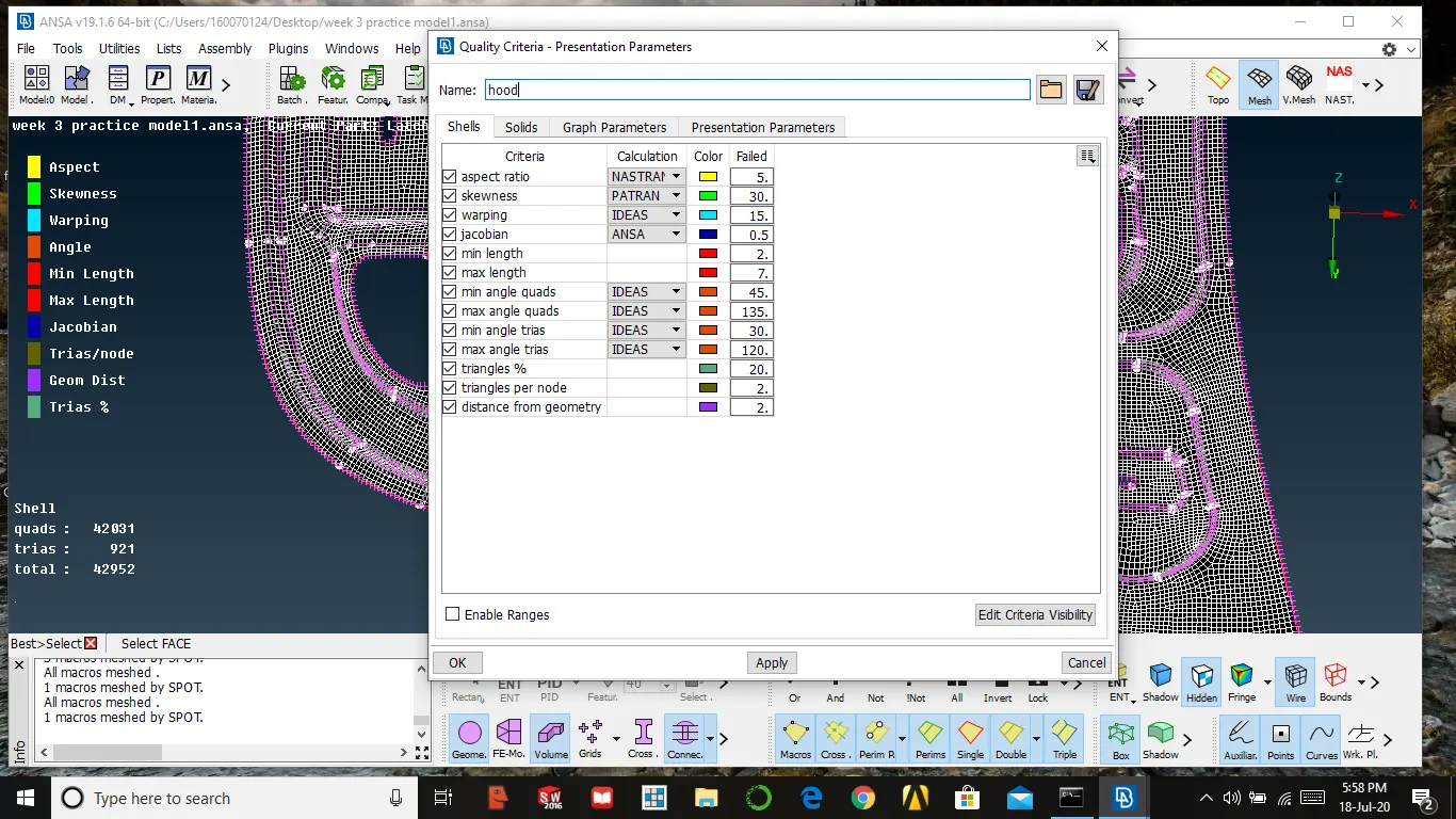
- Then we need to set mesh parameters (target length, minimum and maximum length)
Utilities → parameters → give parameters → apply → ok
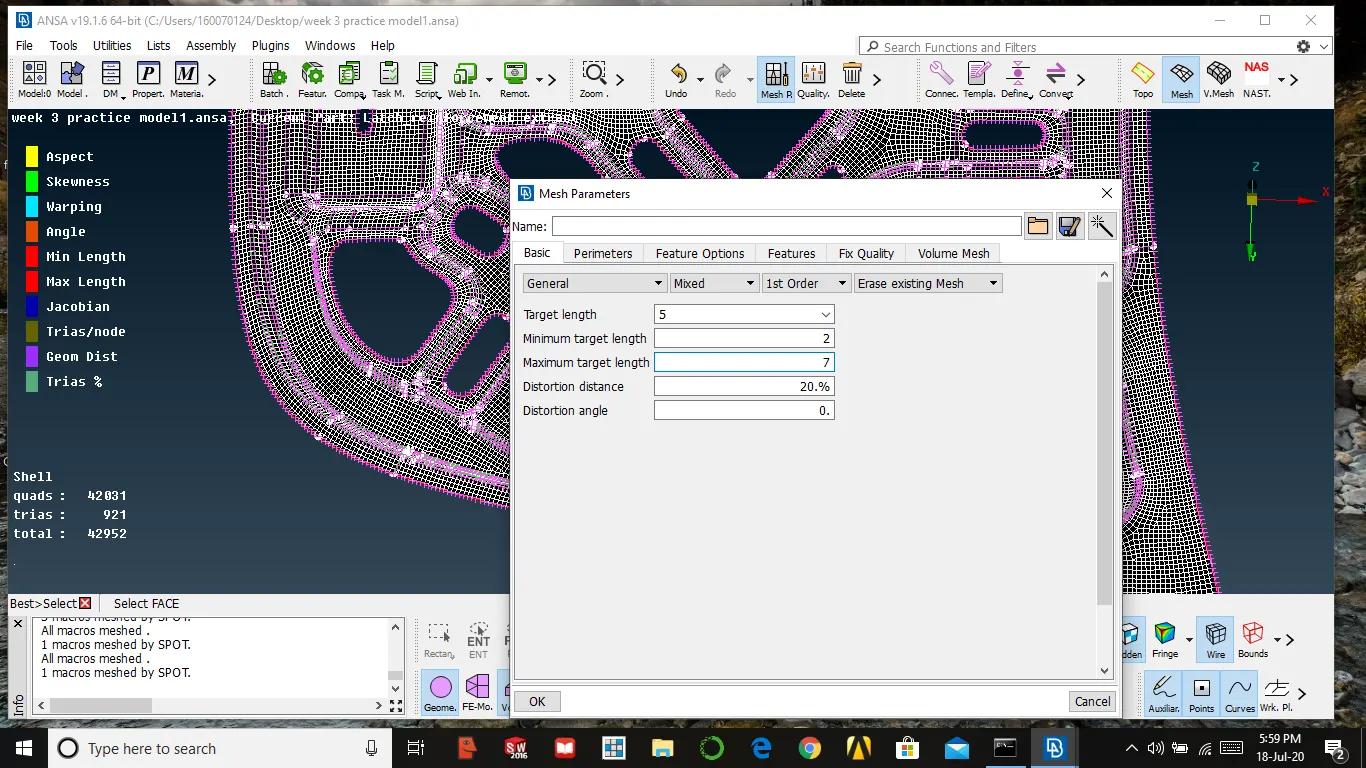
- After that, we need to set a perimeter and macro length as a given target length
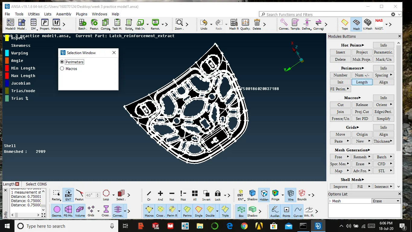
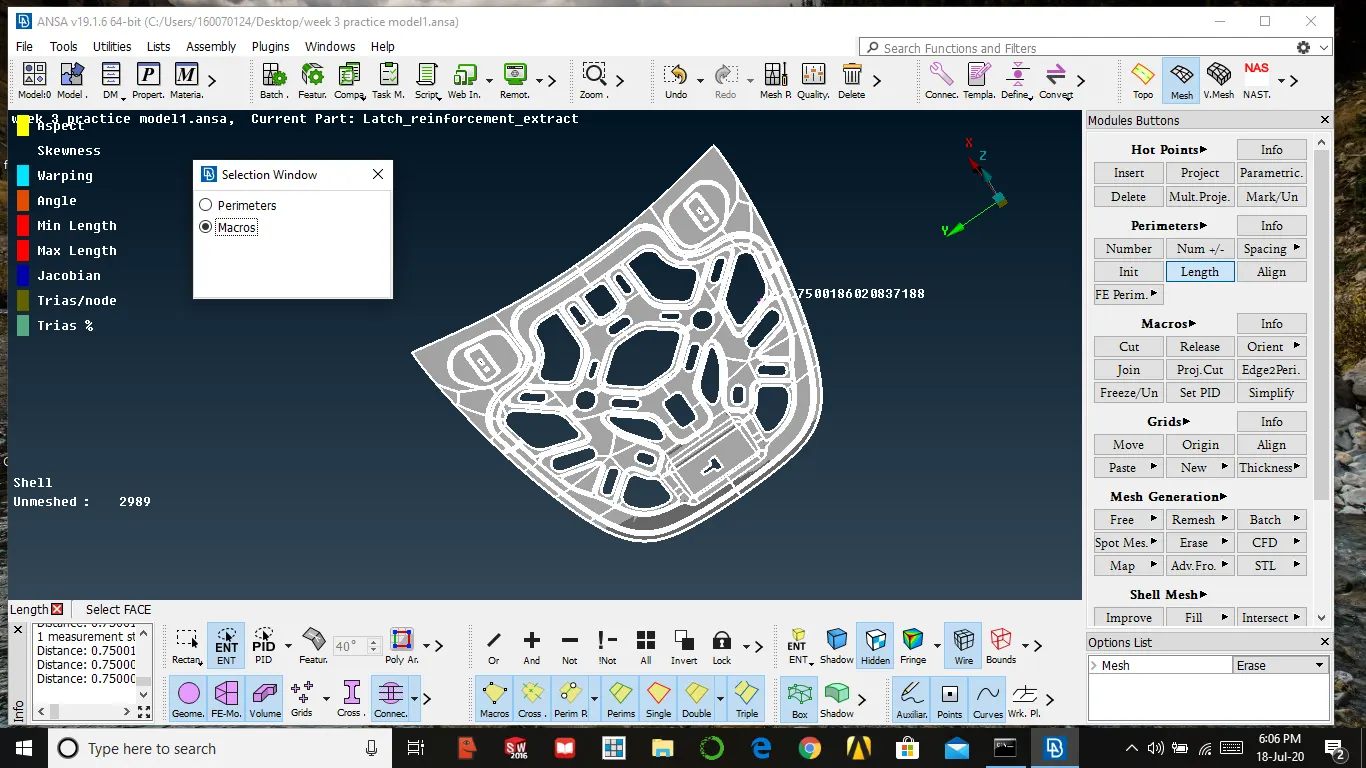
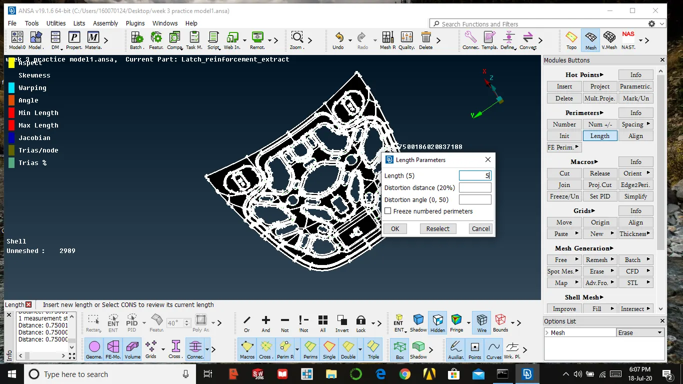
- Delete the construction line that which affect the mesh, arrange construction line perpendicular to get better mesh
- Make sure that do not delete construction line which carries the part construction
Meshing:-
Mesh all the parts where mid surface extracted
Procedure to mesh
Go to mesh module →mesh generation → best → select face → ok
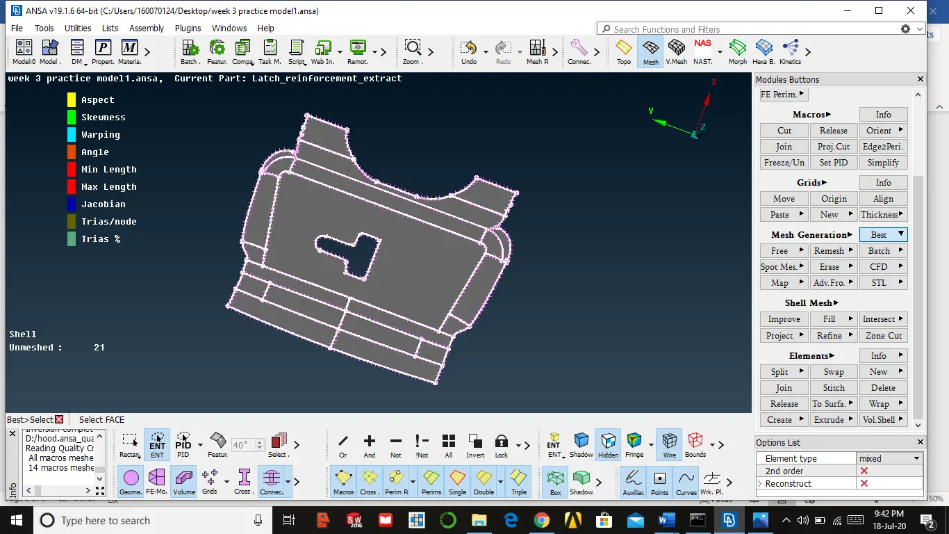
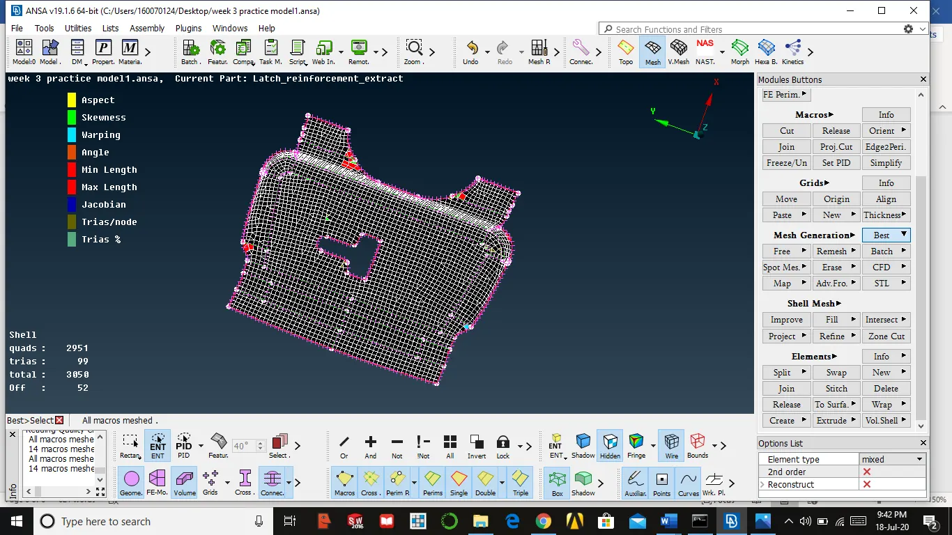
Procedure to refine the mesh
- Go to shell mesh in mesh module select reconstruct → select face which is meshed → middle mouse
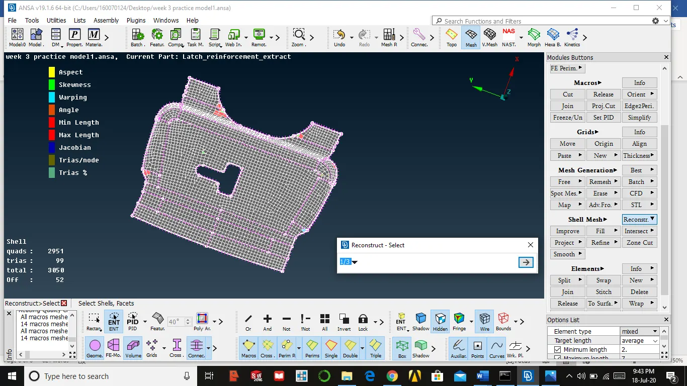
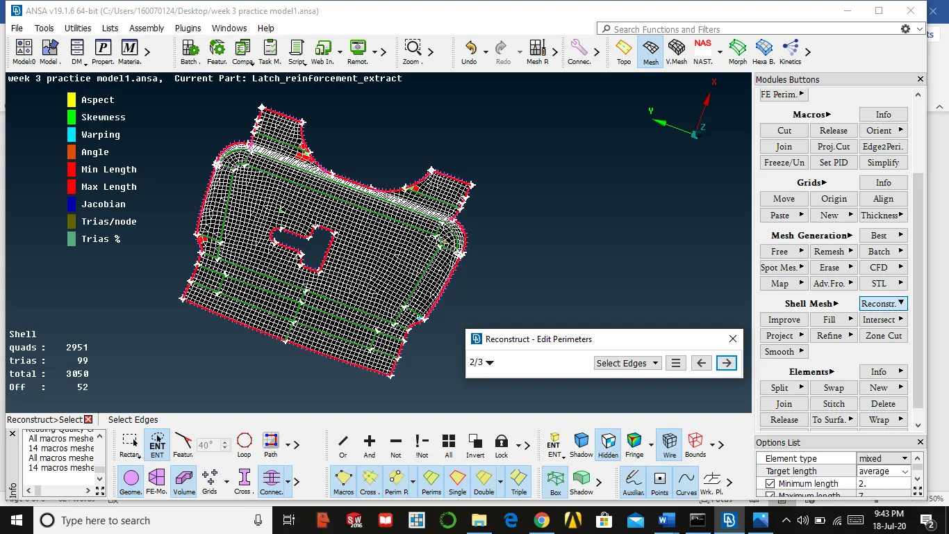
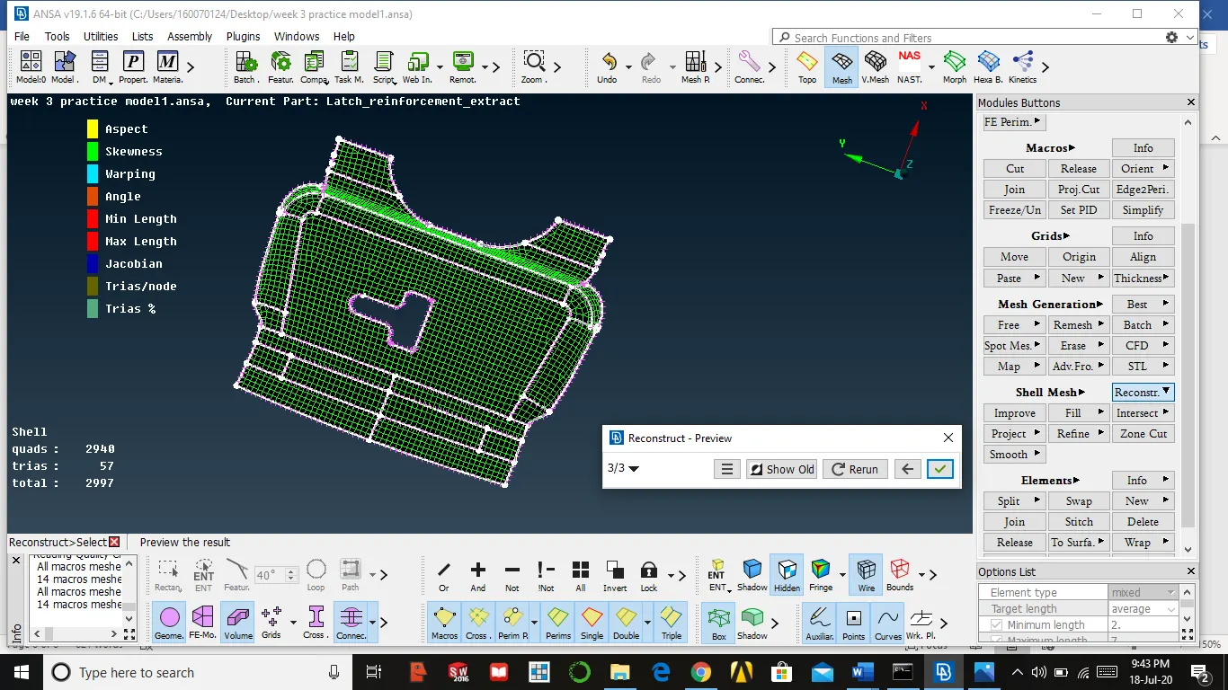
- Go to shell mesh in mesh module select smooth → select face which is meshed → middle mouse

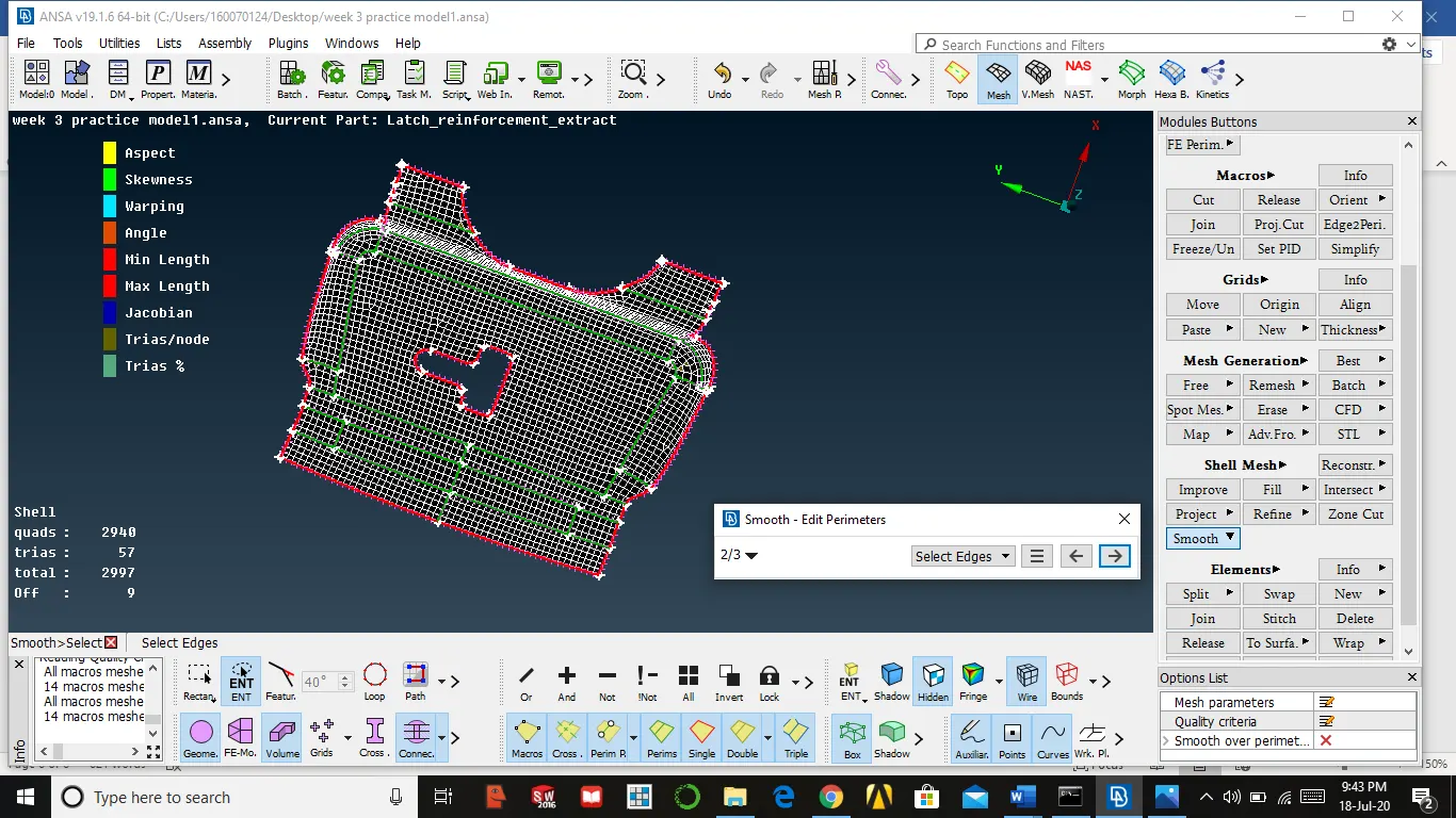
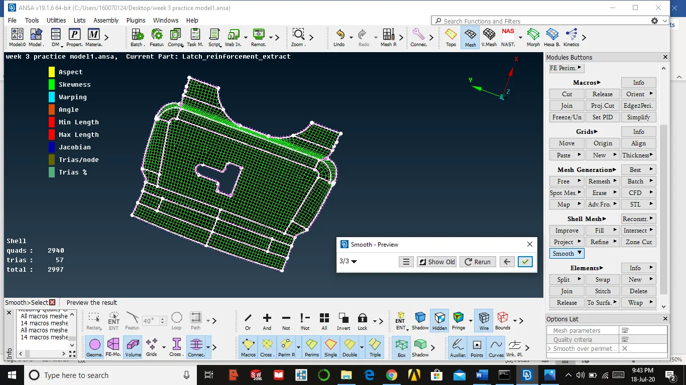
- After completing the above process if any error is being shown u must alter the construction line to make mesh to occupy the space
- The major issues that occur in the mesh are tria elements,tria might occurs but need not be at certain place mention below
- At edges, trias must not present
- At fillet area, trias must not present
- At the perimeter, trias must not present
- Opposites trias must not present
- To remove tria or swap the tria we use split into elements
Procedure to remove opposite trias
- Select split in elements → left click in edge line of tria up to other end → middle mouse → left-click on the diagonal line formed in the middles
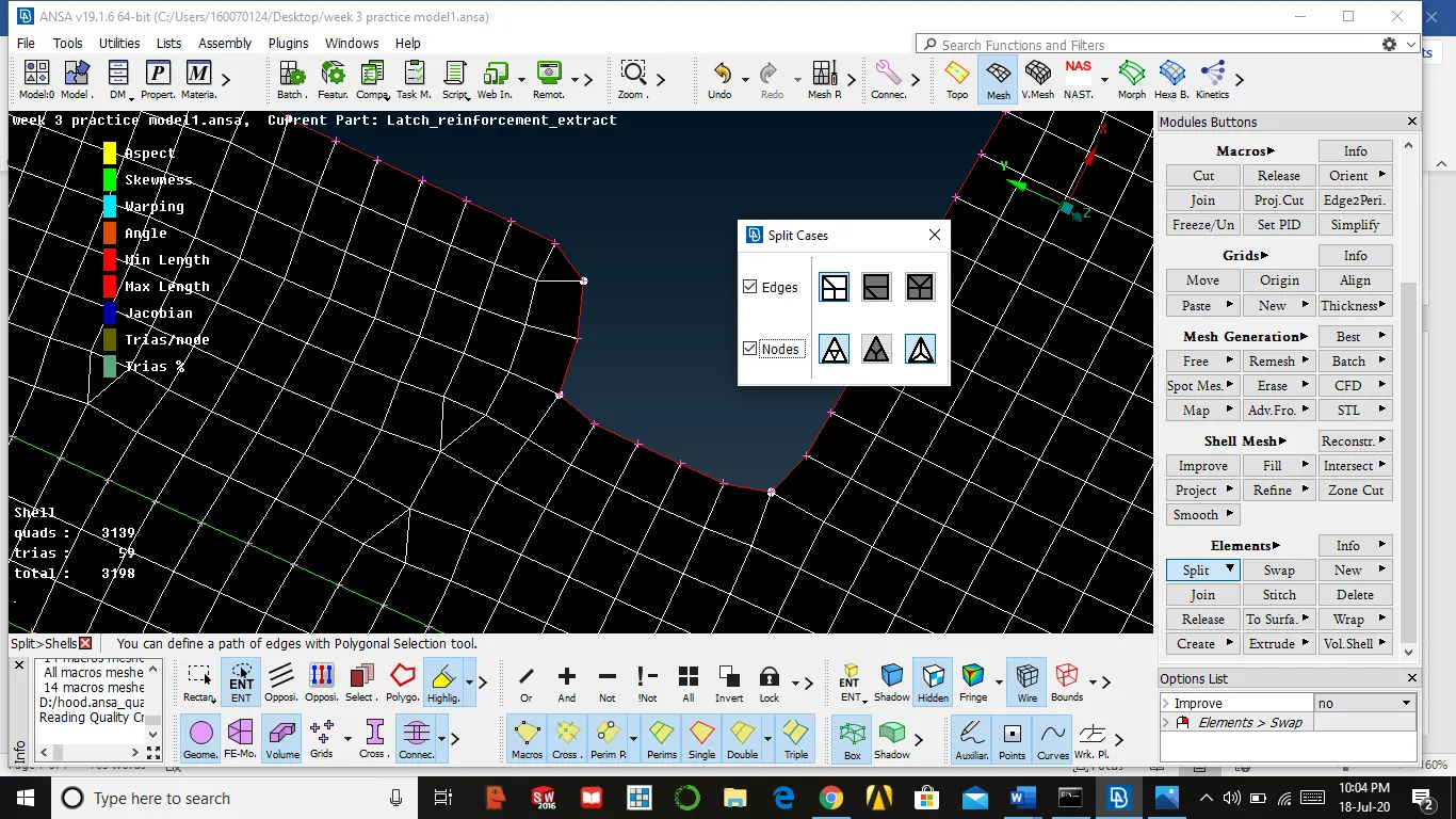
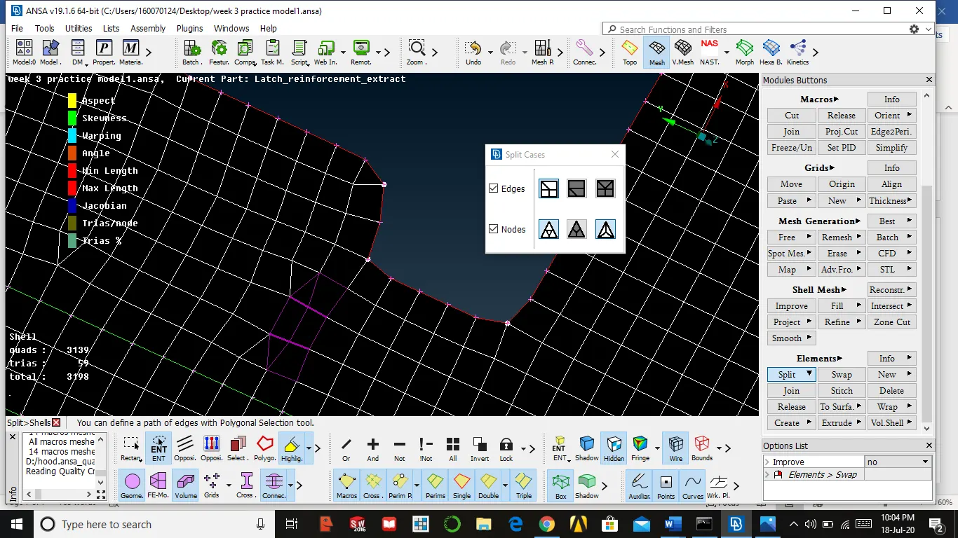
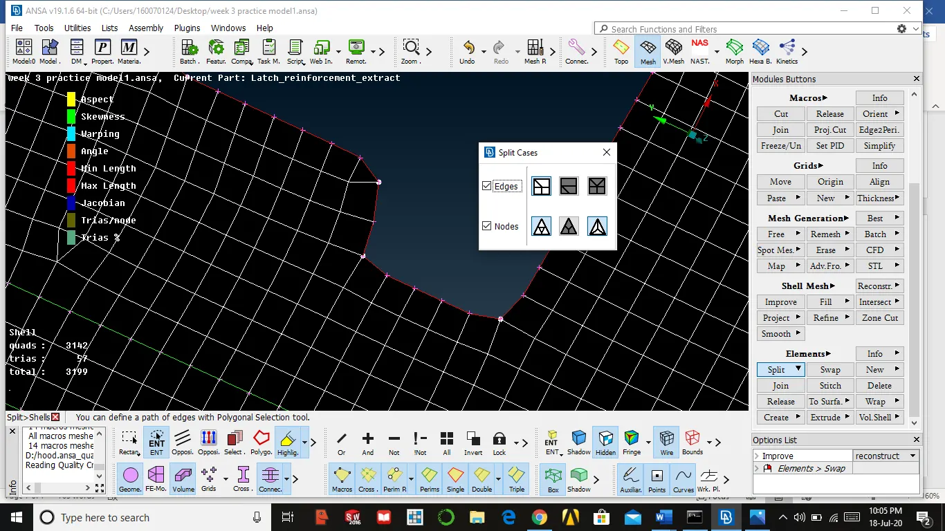
- Select split in elements → options reconstruct/smooth → right-click (which move trias)
- We can remove the trias pointing towards the edge by using split
Quality issues
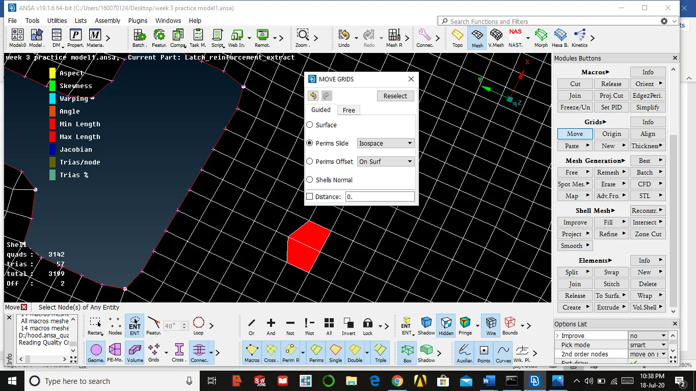
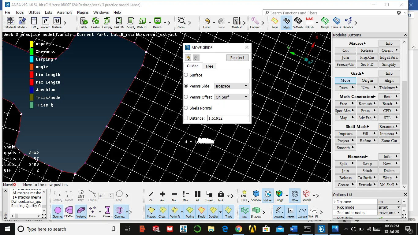
If any quality issues occur by smooth we eliminate if else we can move node by using move option in the grid
Select move in grid → set perim slide → select node → move the node
Meshing for symmetrical parts
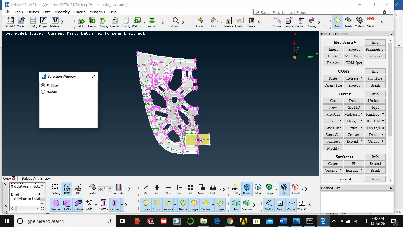
We will do mesh for one side of the part and other parts will be deleted, we will mirror it to the other side by using transform
Delete other faces
Topo module → faces → delete
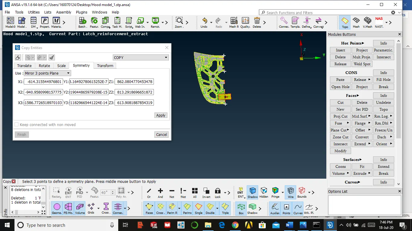
Symmetry for face
Utilities → transform → copy → select component → middle mouse → select symmetry → select mirror three-point plane → select three-point and select
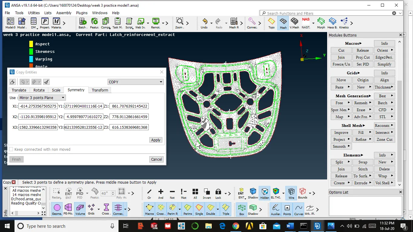
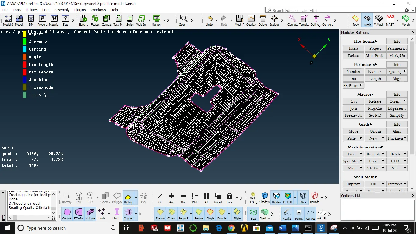
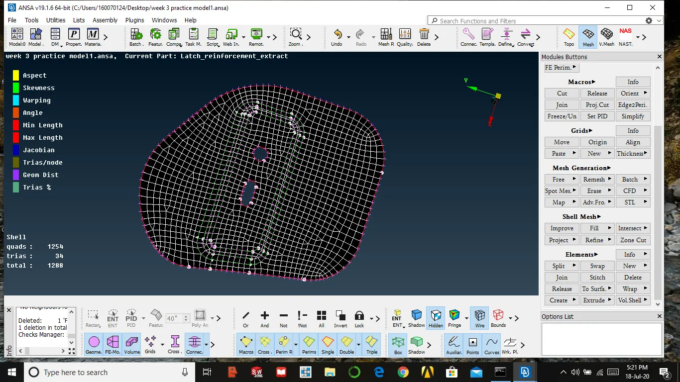
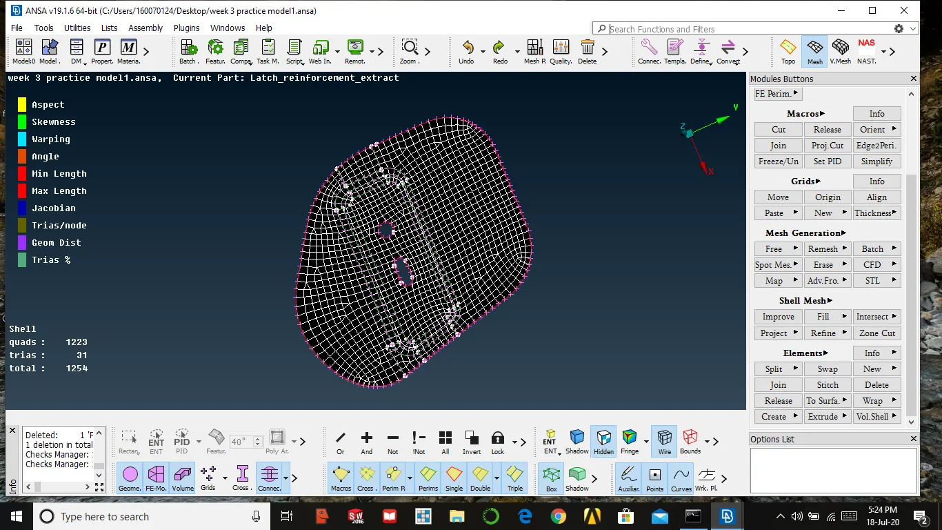
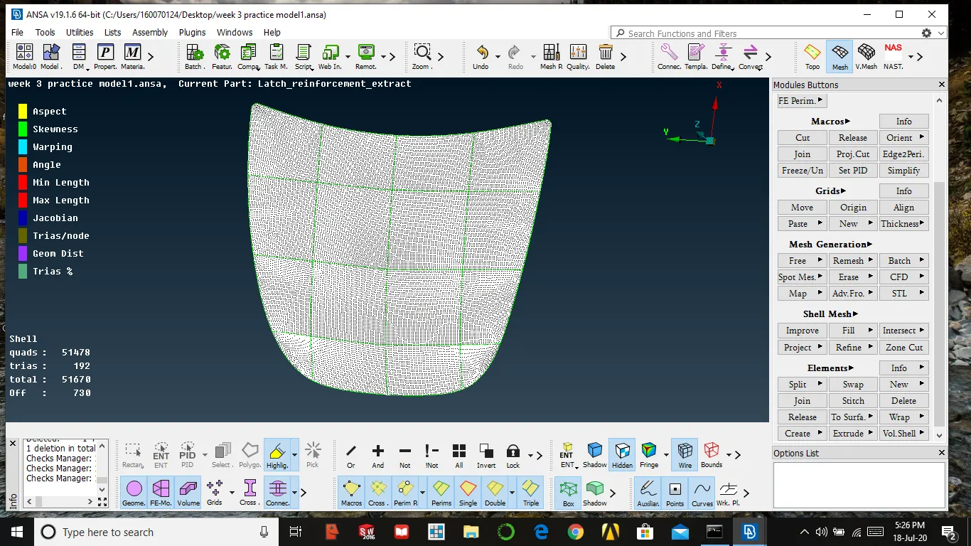
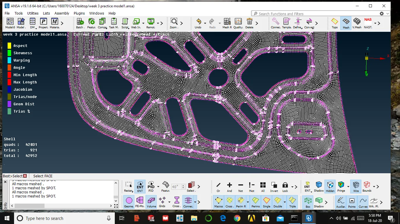
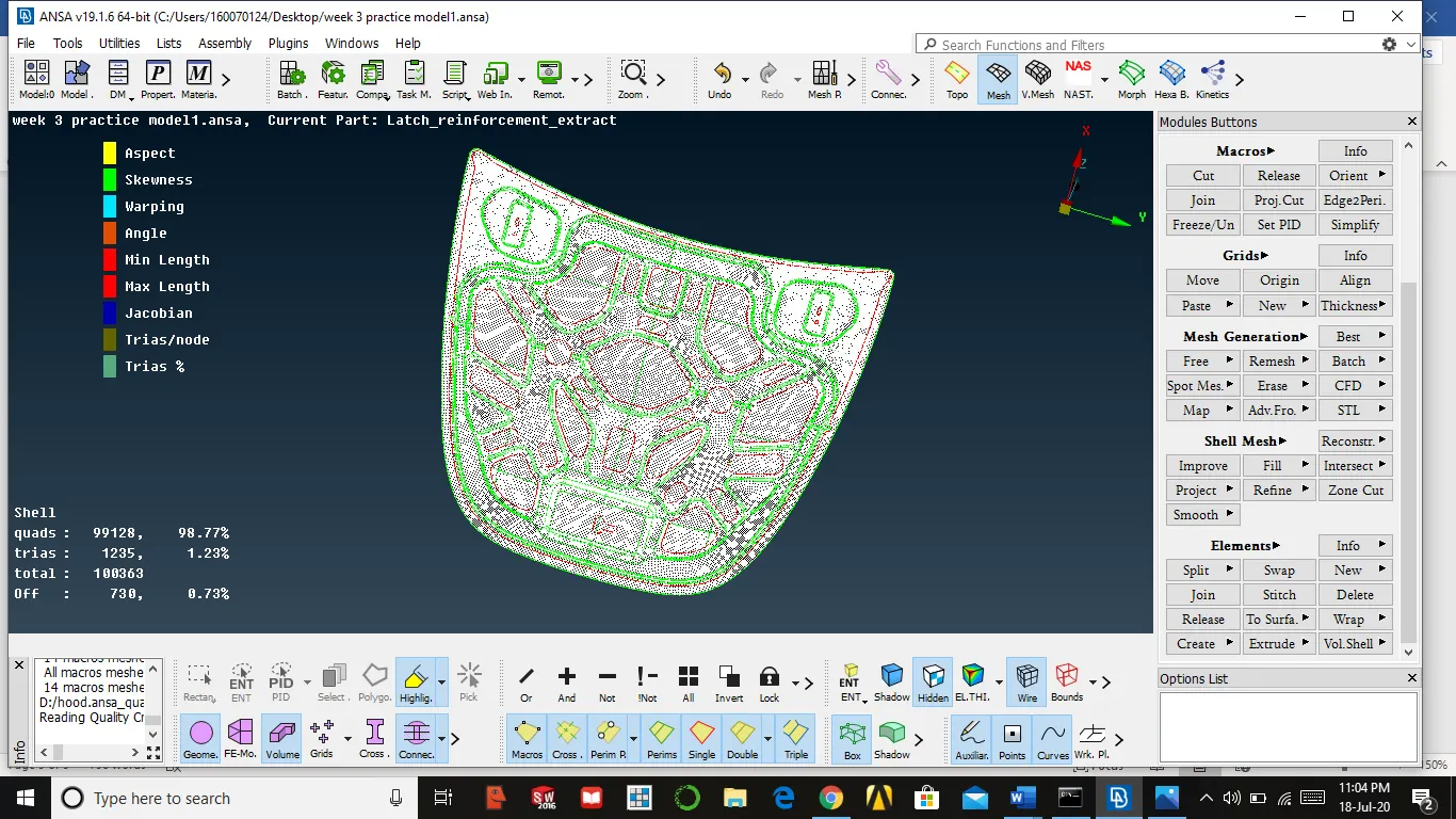
Meshing is done for all components
Conclusion:
- We must clean the geometry of mid surface before entering into the mesh
- We must avoid trias which are facing opposite and back to back
- We must provide perpendicular construction line which enhances the quality of the mesh
- Avoiding trias in a certain area is difficult then we must give space between them
- While comparing tria vs quality, we must give importance to quality first
- By understanding the symmetrical structure of the part we can minimize the time