Week 2 - Flow over a Cylinder.
vortex shedding:
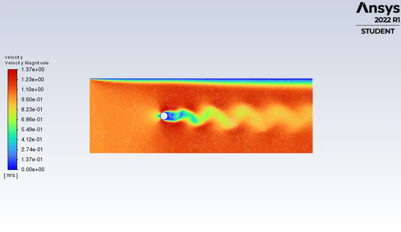
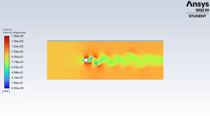
vortex shedding is an oscilating flow that take place when a fluid such as air or water flows past a bluff body at certain velocities depending on the size and shape of the body. in this flow vortices are created at the back of the body and detach periodically from either side of the body forming a von karman street . the fluid flow past the object creates alternating low pressure vortices on the downstream side of the object. the object will tend to move toward low pressure zone.
if the bluff structure is not moubted rigidly and the frequency of vortex shedding matches the resonance frequency of the structure then the structure can begain to resonate vibrating with harmonic oscilation drive by the energy of the flow . the vibration is cause for overhead power line wires humming in the wind and for the fluttering of automobile whip audio antennas at some speeds. tall chimneys constructed of thin walled steel tubes can be sufficient flixible that in airflow with a speed in the critical range vortex shedding can drive the chimney into violet oscilations that can damage or destroy the chimney.
von karman street :
in fluid dynamics a von karman street is a repeating pattern of swirling vortices caused by a process known as vortex shedding which is responsible for the unsteady seperation of flow of a fluid around blunt bodies.
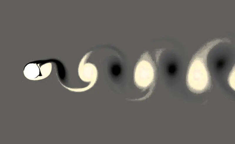
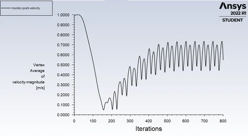
a vortex street will form only at certain range of flow velocities specified by a range of reynold number as shown in above it must have re value of about 90.
strouhal number:
strouhal number is a dimensionless number describing oscillating flow mechanisms.
it is ofen used as
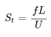
f= frequency of vortex shedding
L= characteristic length
U=flow velocity.
procedure:
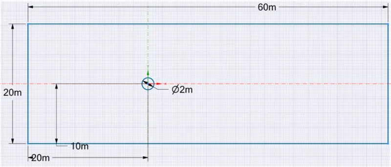
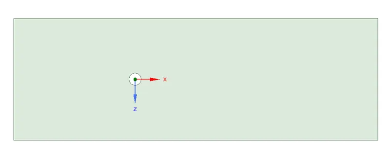
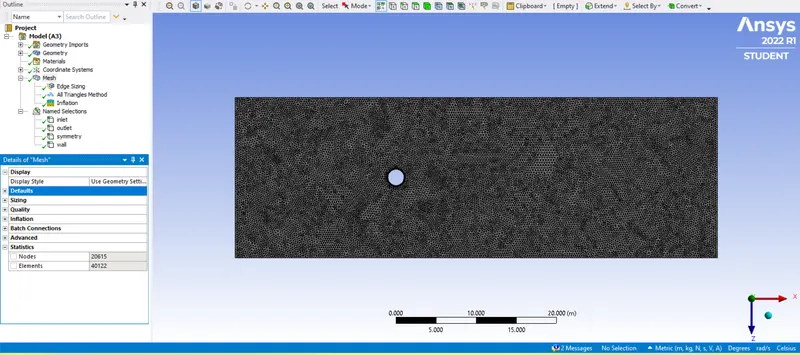
object: is we have diameter of 2m horizantal length is of total 60m vertical length is of 20m as shown below.
mesh:
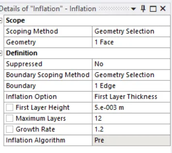
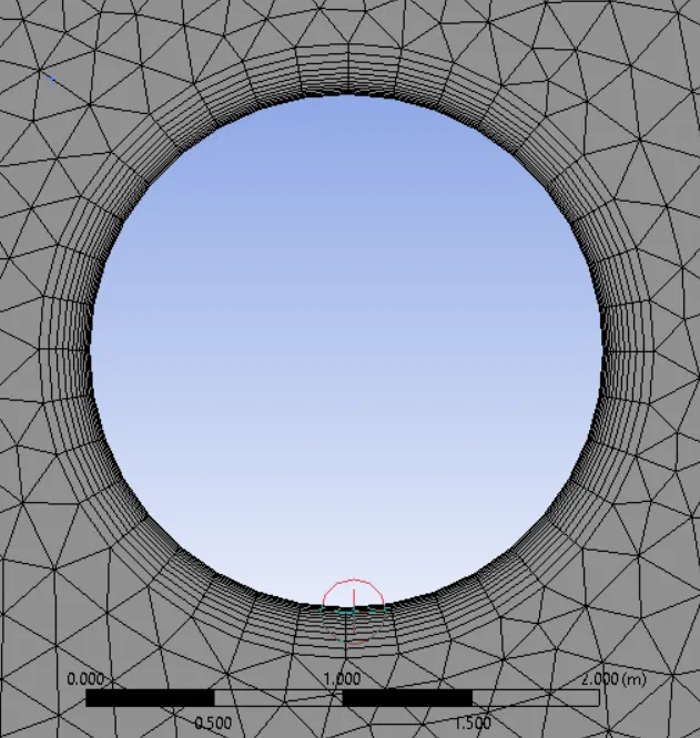
1 traingle mesh
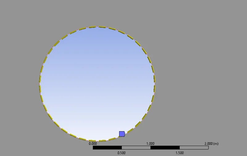
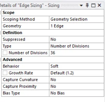
2 edge size
3 inflation layer
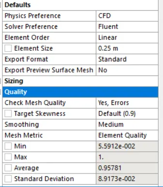
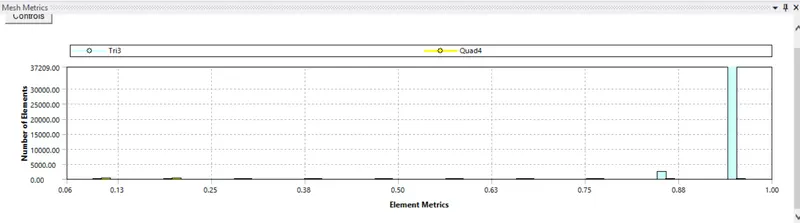
quality:
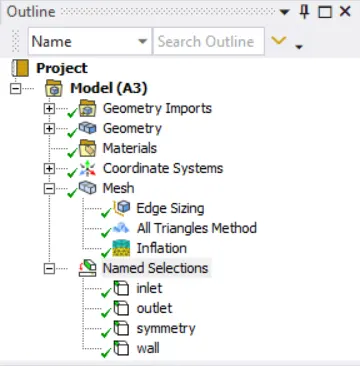
created name section:
fluent base setup:
check the mesh
setup
general type pressure based , absolute velocity formation & time = both steady and transient.
viscous model = laminar
materials= air fluid material from fluent database
cell boundaries conditions= user defined fluid in the region
boundary condition= cyclinder wall is stationary wall no slip boundary coundition
inlet is velocity inlet , absolute velocity magnitude calculated with respect to renolds number
outlet is pressure outlet,absolute gauge pressure is 0pa
symmetry
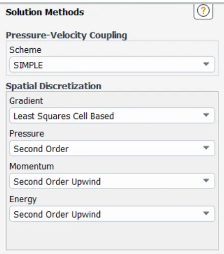
solution method:
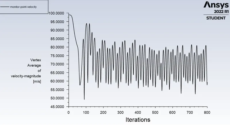
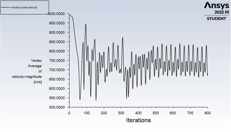
we have created monitor point at length of 4D=8m of the cyclinder+veside
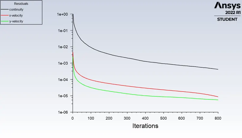
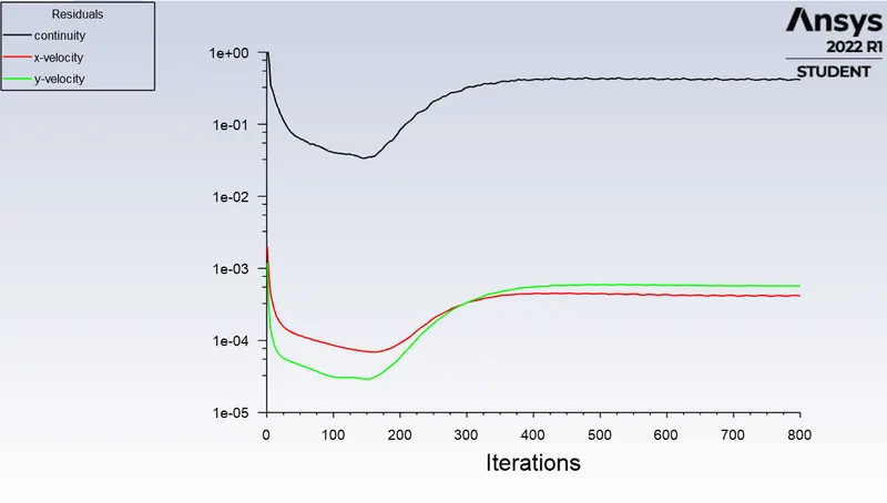
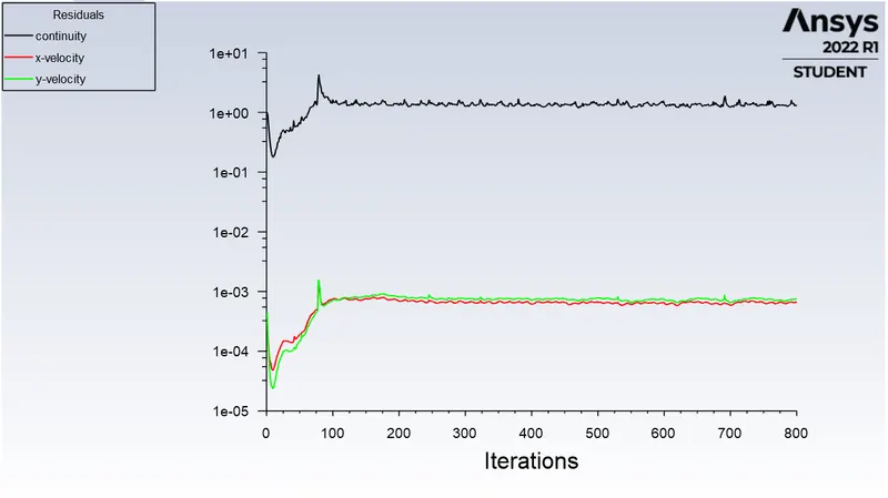
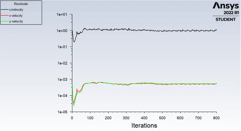
residual monitor:
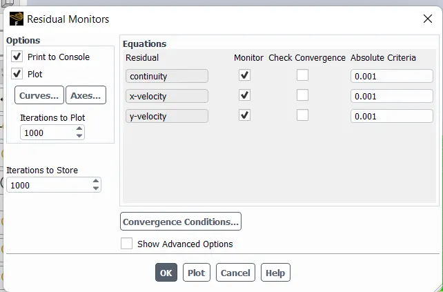
Hybrid initilaization

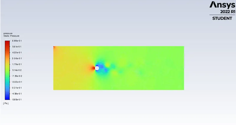
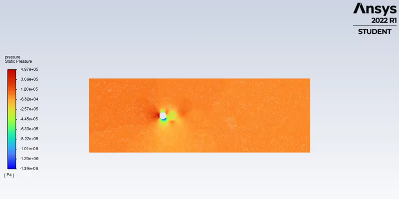
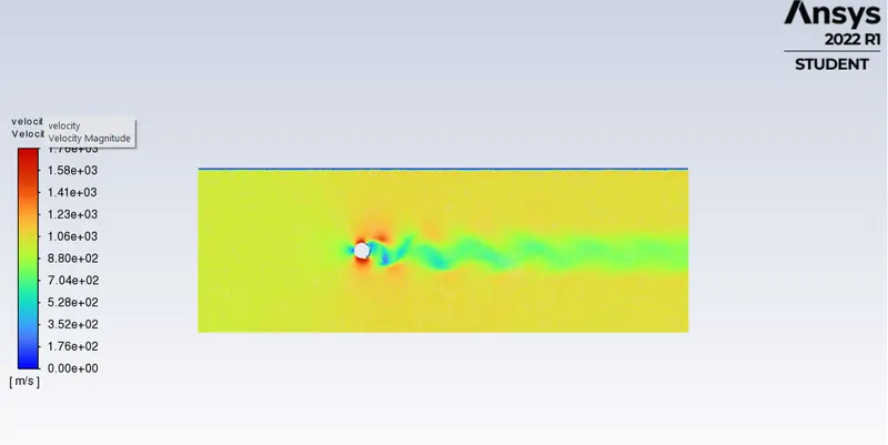
velocity and pressure contour:
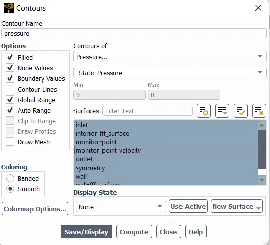
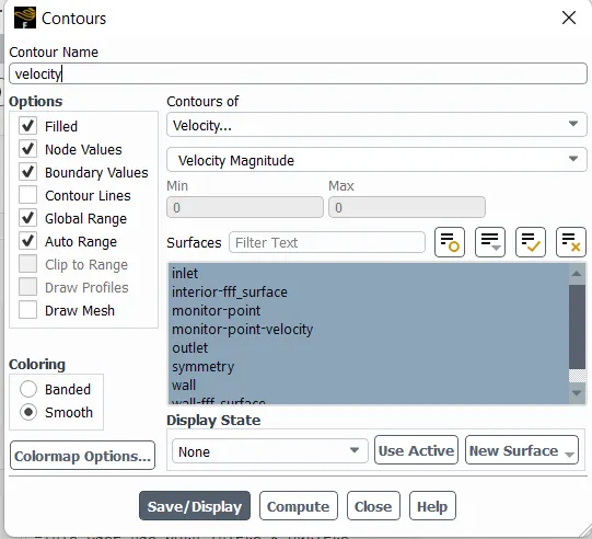
for trasient time calculation
v=1m/s, L =60 m time step size=0.2 sec
time step = L/v.time step= 60/1*0.2= 300
the number of time iteration step should be greater than or equal to 300 in this simulation we were given 800 timestep with maximum iteration for time step is 10.
result:
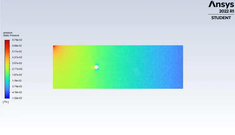
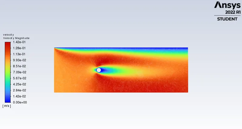
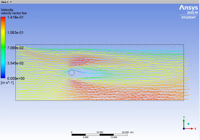
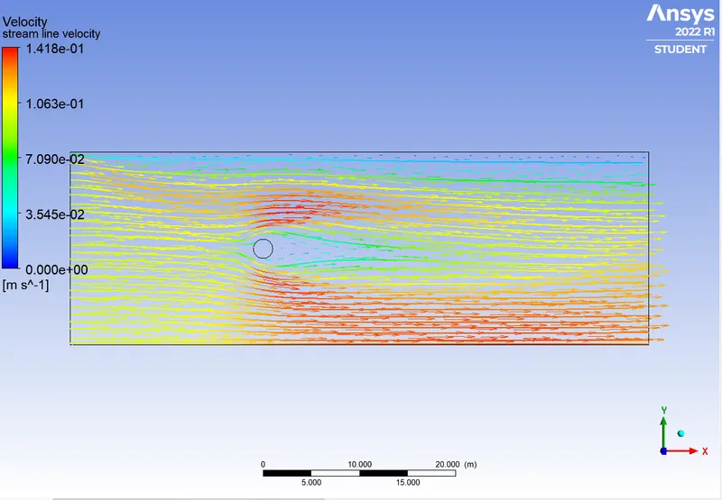
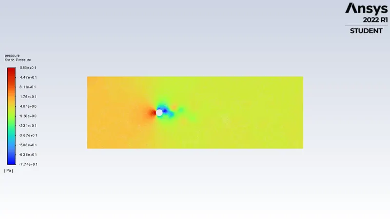
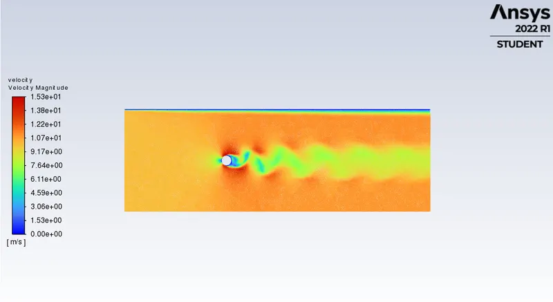
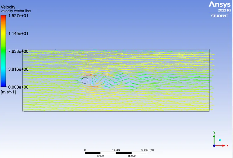
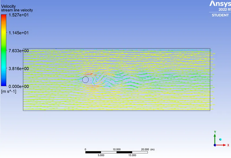
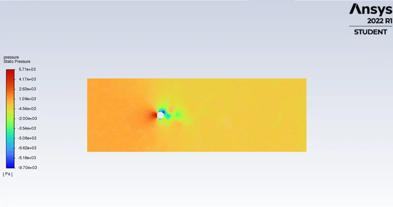
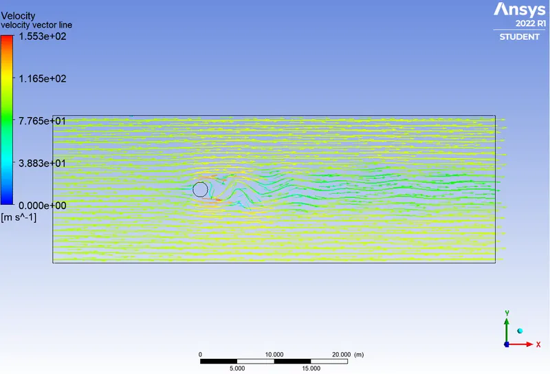
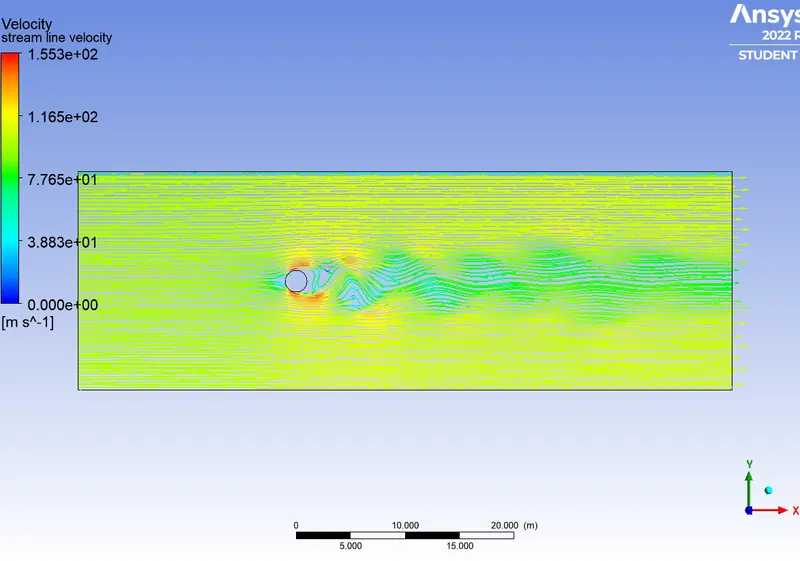
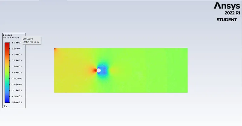
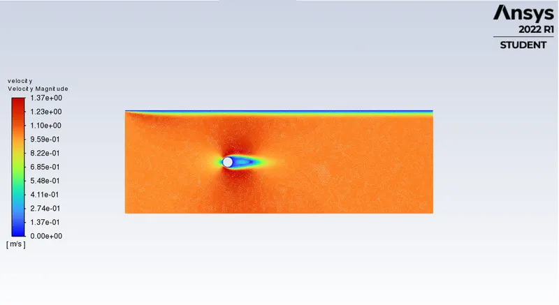
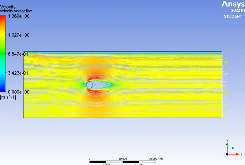
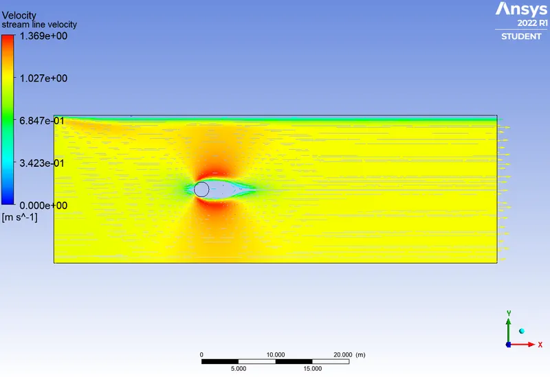
velocity contour, pressure contour, velocity stream line , velocity vector on xy plane.
velocity calculation
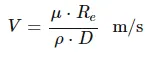
diameter = 2m
density= 1 kg/m^3
dynamic viscosity = 0.02 kg/ms
V=( D_V*Re)/(Rho*D)
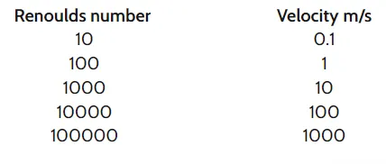
steady state simulation :
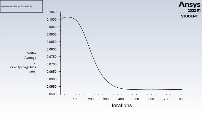
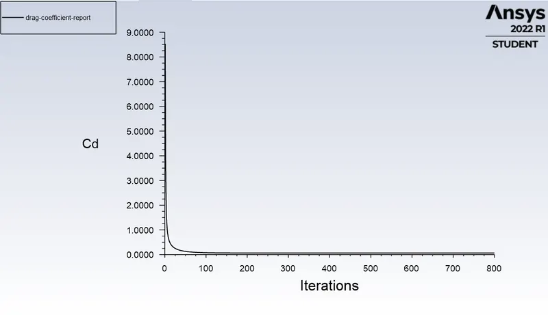
1: reynold number = 10 velocity =0.1 m/s
video link:
https://drive.google.com/file/d/153_cnUBEHlhoD2b77oCpiKf6sUp_P_lP/view?usp=sharing
https://drive.google.com/file/d/1tBgc8GuwhbEXNhNg8XmFNVBs--rV0ULw/view?usp=sharing
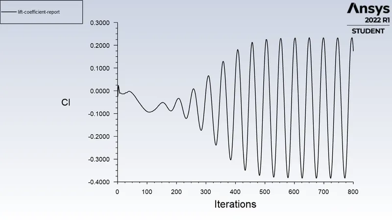
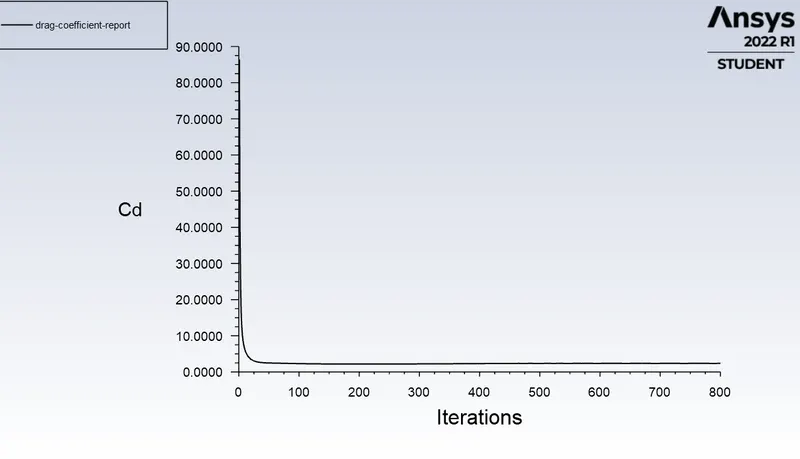
2: reynold number= 100 velocity =1 m/s
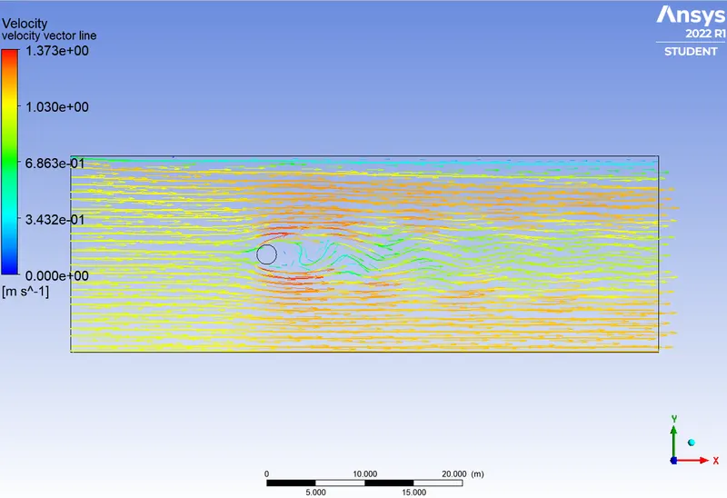
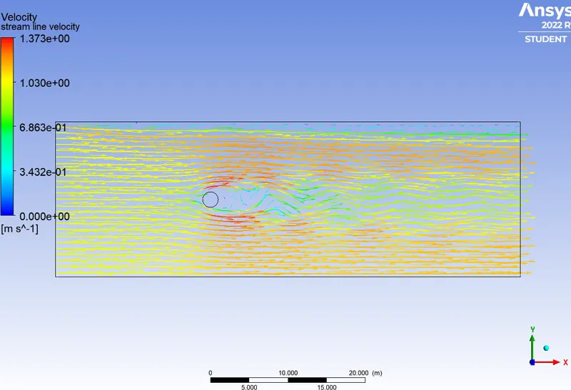
video link:
https://drive.google.com/file/d/1_iSgC0hnDxRAeSBUXixup7MG8HKvLerC/view?usp=sharing
https://drive.google.com/file/d/1zJA22RjYV3Sq_UR1vteaihdOC4KQSnso/view?usp=sharing
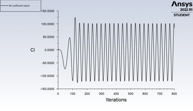
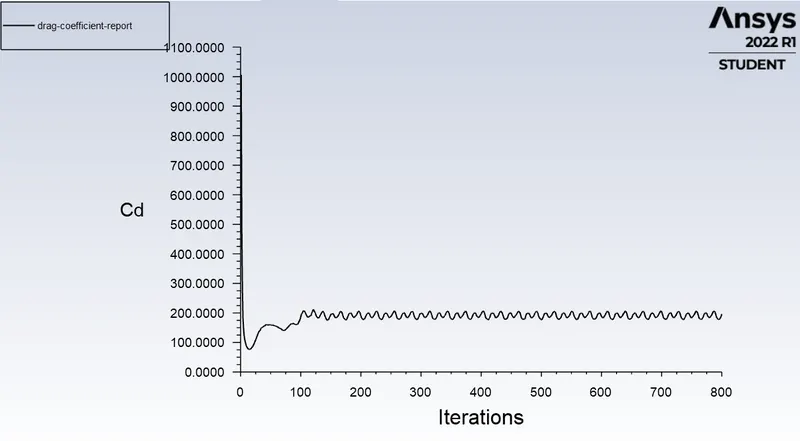
3 : renolds number = 1000 velocity = 10 m/s
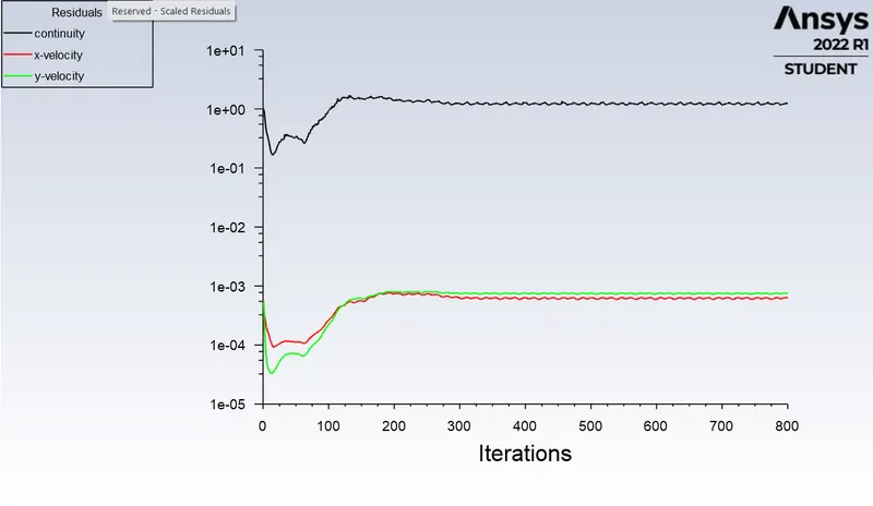
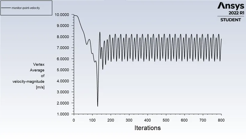
video link:
https://drive.google.com/file/d/1sAH3p2DWZXXD0sh8mR4Oa7EYP_EHPmWP/view?usp=sharing
https://drive.google.com/file/d/1fQKwJNzlcSB-PJ9HIUYBReXZvYUUworR/view?usp=sharing
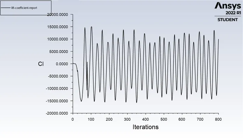
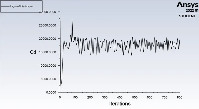
4 : renolds number = 10000 velocity = 100 m/s
video link:
https://drive.google.com/file/d/1BGpdiySGSVDNc_rbrkKEQELOkfuvUbdS/view?usp=sharing
https://drive.google.com/file/d/1DmK_FK_1kvfqJfuZUDzlCRyXAiZufUQV/view?usp=sharing
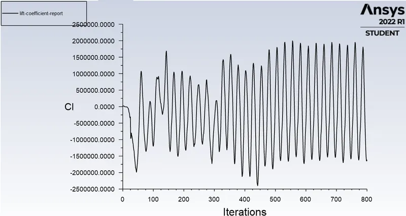
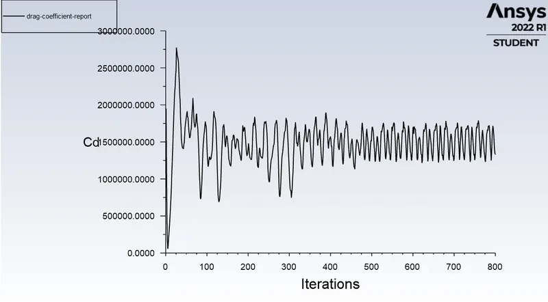
5 : renolds number=100000 velocity= 1000 m/s
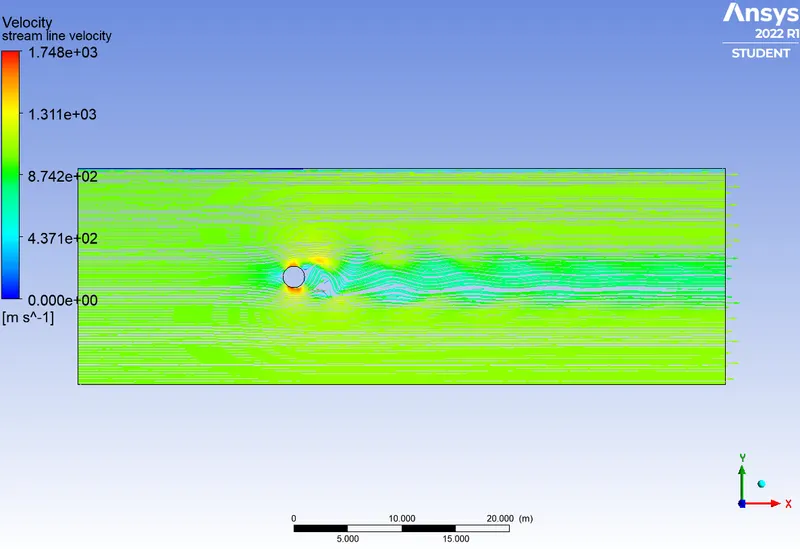
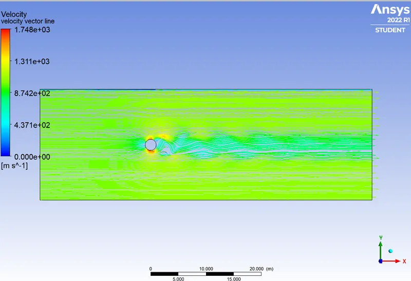
video link:
https://drive.google.com/file/d/1yX3vG31IZEi6f2wJ3G02Zgdx1nqFyXaR/view?usp=sharing
https://drive.google.com/file/d/13IbzJY4l79BQ9jPg7eDxf2ncnwUtW5NV/view?usp=sharing
transient state simulation:
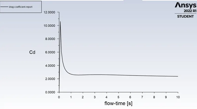
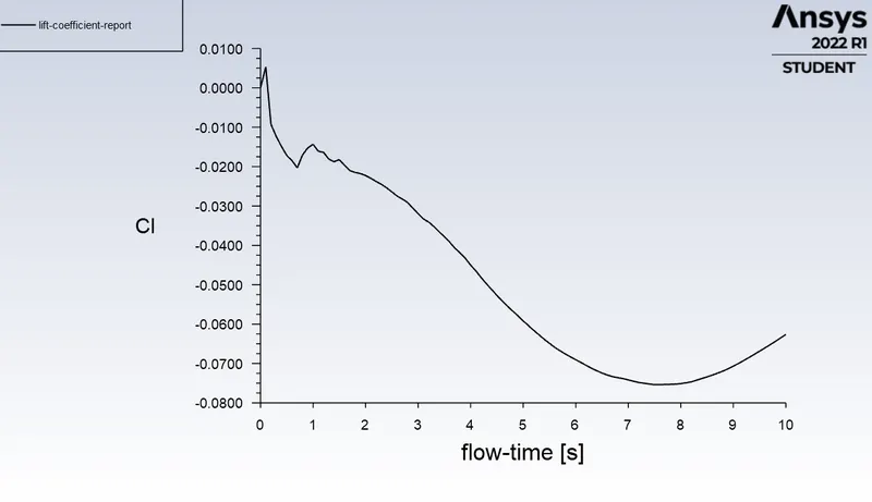
1: reynold number=100 velocity=1 m/s simulation=100 sect with step size=0.1sec
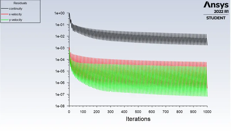
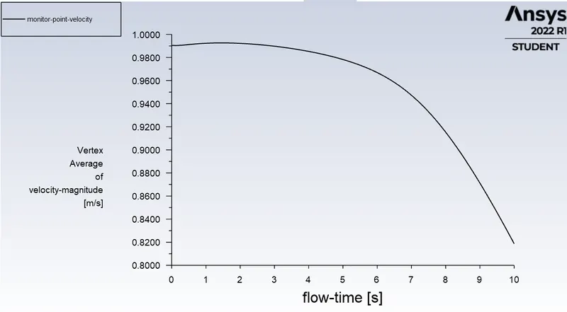
video link:
https://drive.google.com/file/d/1jwtX-ybMGR1Z11AsdyeycnUY5cf9H2Cz/view?usp=sharing
https://drive.google.com/file/d/1smPDCpdAokK1yHcCfeRsR4z99AoOqxdd/view?usp=sharing
conclusion:
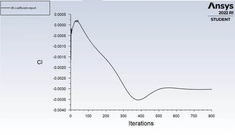
1 as the reynolds number increses drag coefficient decreases and lift coefficient increases.
2 transient state capture more accurate vortex sheding than steady state solving..