Week -2
AIM:
To Make a simulink model of doorbell using solenoid block and to use a thermistor to sense the temperature of a heater & turn on or turn off the fan.
Block diagram for doorbell using solenoid block :
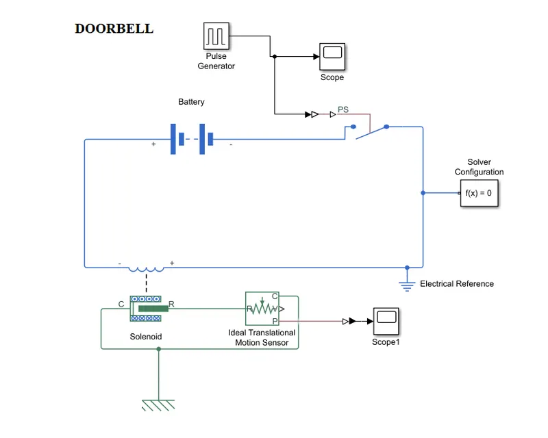
components of the simulink model used in Doorbell using solenoid block:
1.Pulse Generator
2.scope
3.simulink -ps converter
4.switch
5.solver configuration
6.electrical reference
7.solenoid
8.ideal translational motion sensor
9.scope1
10.mechanical translational reference
11.battery
12.ps-simulink converter.
Simulink model used for doorbell using solenoid is constructed with compeonents that are given above . For power source battery is connected and to switching on and off the doorbell a electrical switch is used .The Pulse Generator block generates square wave pulses at regular intervals.The block waveform parameters, Amplitude, Pulse Width, Period, and Phase delay, determine the shape of the output waveform.
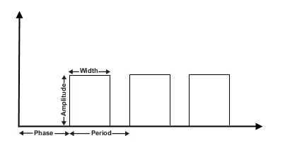
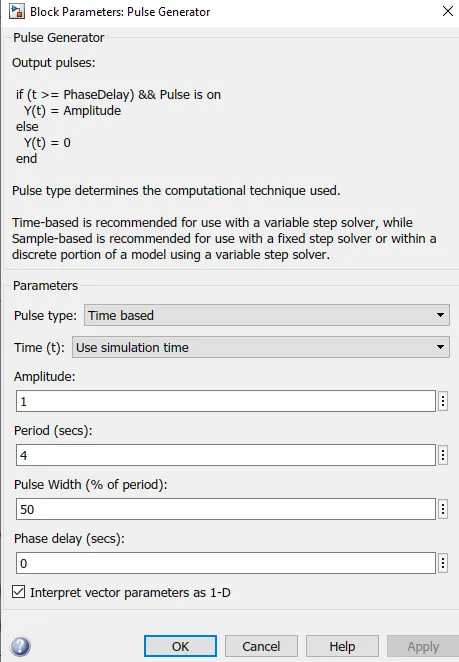
Pluse generator is the time based pulse type.where the parameters are given in block parameter dialogbox.
After providing the pulse generator parameters,the simulink to ps converter is connected to switch.then solenoid and ideal translational sensors are connected .for reference to the electrical and mechanical supply.the Mechanical Translational Reference and electrical reference are connected side by side.for the motion of the mechanical arm the there is a sensor which I already recivies the signal.plot the reading of flow in scope block.For solving the electrical circuit the solver configuration is used.
Solver configuration:
Each physical network represented by a connected Simscape block diagram requires solver settings information for simulation. The Solver Configuration block specifies the solver parameters that your model needs before you can begin simulation.
Results for doorbell using solenoid block :
SCOPE :
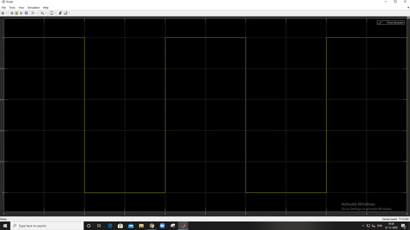
In this Scope the amplitude releases for 2 second and increase as the doorbell rings.the 2second of the amplitude release is known as period.on X-axis there is time and for the Y-axis it is amplitude.
SCOPE 1:
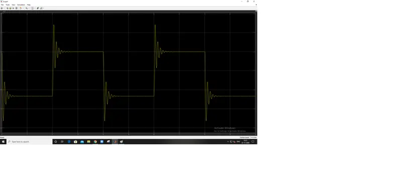
In this plot the ideal translational motion sensor movements are captured in scope and displayed in this format.
Simulink Model for thermistor to sense the temperature of a heater:
Using a thermistor to sense the temperature of a heater & turn on or turn off the fan.
Given Values: Temperature source: 20 °C from 0 to 10 seconds, 27 °C from 10 to 30 seconds, 23 °C from 30 to 50 seconds.
Fan condition: ON if the temperature above 25 °C, OFF otherwise
- Thermistor:
A thermistor is a resistance thermometer, or a resistor whose resistance is dependent on temperature. The term is a combination of “thermal” and “resistor”. It is made of metallic oxides, pressed into a bead, disk, or cylindrical shape and then encapsulated with an impermeable material such as epoxy or glass.
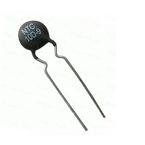
In this thermistor is used for sensing the temperature of the heater and turning on and off the heaters fan with above given condition. the fan condition is "ON if the temperature above 25 C ,OFF otherwise".
simulink model for thermistor is constructed with repeating sequence stair1.
- Repeating sequence stair:
The Repeating Sequence Stair block outputs and repeats a stair sequence that you specify with the Vector of output values parameter.
- Simulink-PS Converter:
The Simulink-PS Converter block converts the input Simulink signal into a physical signal. Use this block to connect Simulink sources or other Simulink blocks to the inputs of a Physical Network diagram.
- Thermal Reference:
The Thermal Reference block represents a thermal reference point, that is, a point with an absolute zero temperature, with respect to which all the temperatures in the system are determined.
- Controlled Temperature Source :
The Controlled Temperature Source block represents an ideal source of thermal energy that is powerful enough to maintain specified temperature difference across the source regardless of the heat flow consumed by the system.
components of the simulink model for thermistor:
- Repeating Sequence Stair1
- Scope
- Simulink-PS Converter
- Thermal Reference1
- Controlled Temperature Source
- Thermistor
- Solver Configuration
- Battery
- Thermistor
- Resistor
- Voltage Sensor
- Electrical Reference
- PS-Simulink Converter1
- Scope1
- Scope2
- Display1
- Display2
- lamp
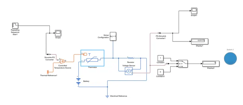
In the below block diagram ,temperature of the heater is applied to the thermistor to sense it.from the given condition when the temperature reaches above 25 degc .fan is triggered with power supply from the electric circuit .it helps the temperature constant.In this the fan condition is satisfied . for indication of thus satisfaction the blue color lamp is shown in below diagram.(blue is cooling)
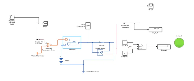
In this condition the temperature is maintained which is below 25 degc ,so therefore fan stays off.
conculsion :
Simulink model of doorbell using solenoid and use of thermistor to sense the temperature of a heater to turn it on and turn off the fan with given condition is carried out sucessfully. the components which are derived are sucessfully constructed and executed.