Fender Design Challenge
AIM:
The primary Function of fender: Fender is the American English term for the part of an automobile, motorcycle or other vehicle body that frames a wheel well (the fender underside). Its primary purpose is to prevent sand, mud, rocks, liquids, and other road spray from being thrown into the air by the rotating tire.
The similar front section between the door and the hood (bonnet) is called a fender (front wing), and may sometimes also be referred to as a quarter panel. Quarter panels are typically made of sheet metal, but are sometimes made of fiberglass, carbon fiber, or fiber-reinforced plastic.
In a Car, the sheet metal parts for the bodywork are created and stamped by robots. These parts form side frames, doors, hoods, and roofs, which are later added onto the main frame of the car. Once the frame is created and the parts are ready to be assembled, the car will be loaded onto a production line.
Manufacturing Processes behind making Fenders
For automotive metal forming, the blank is often made of sheet metal, which can be stamped, cut or bent into a shape needed for an automobile's body. Alternatively, it can be a solid block of metal in a cubical or lens-like shape. Here are some ways that a metal workpiece can be deformed during the automotive manufacturing process:
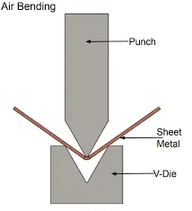
Bending: Bending is a forming operation in which a sheet metal is subjected to bending stress thereby a flat straight sheet is made into a curved sheet. The sheet gets plastically deformed without change in thickness. Die and punch are used for bending. If a v shaped die and punch are used, the bending is called v-bending.
Deep Drawing:
Deep drawing is a sheet metal forming process in which a sheet metal blank is radially drawn into a forming die by the mechanical action of a punch. It is thus a shape transformation process with materialretention. The process is considered "deep" drawing when the depth of the drawn part exceeds itsdiameter. This is achieved by redrawing the part through a series of dies. The flange region (sheet metal in the die shoulder area) experiences a radial drawing stress and a tangential compressive stress due tothe material retention property. These compressive stresses (hoop stresses) result in flange wrinkles(wrinkles of the first order). Wrinkles can be prevented by using a blank holder, the function of which is
to facilitate controlled material flow into the die radius.
Stamping:
Stamping (also known as pressing) is the process of placing flat sheet metal in either blank or coil form into stamping press a Stamping where a tool and die surface forms the metal into a net shape. Stamping includes a variety of sheet-metal forming manufacturing processes, such as punching using a stamping press, blanking, embossing, bending, flanging, and coining.

This could be a single stage operation where every stroke of the press produces the desired form on the sheet metal part, or could occur through a series of stages. The process is usually carried out on sheet metal, but can also be used on other materials, such as polystyene.
Embossing:
Sheet metal embossing is a stamping process for producing raised or sunken designs or relief in sheet metal. This process can be made by means of matched male and female roller dies, or by passing sheet or a strip of metal between rolls of the desired pattern.
Design:
given skin data:
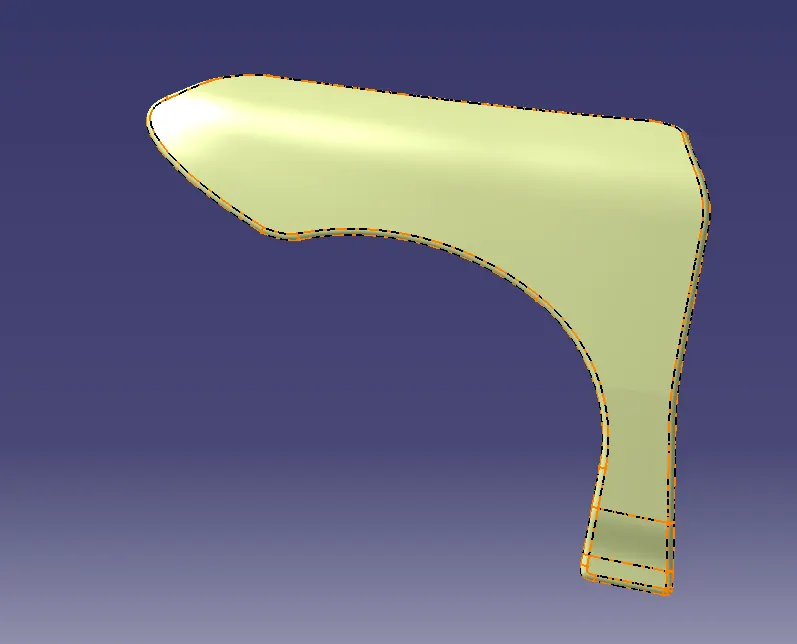
creating parallel lines at the edges for drip area & other respective areas
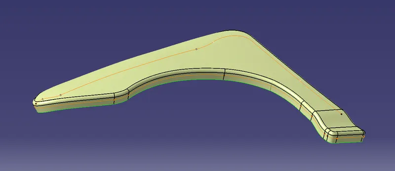
spliting those lines for cut out:
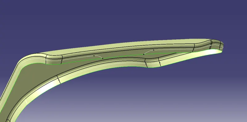
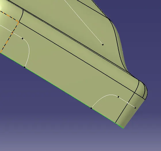
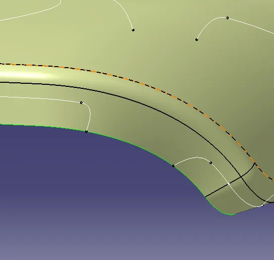
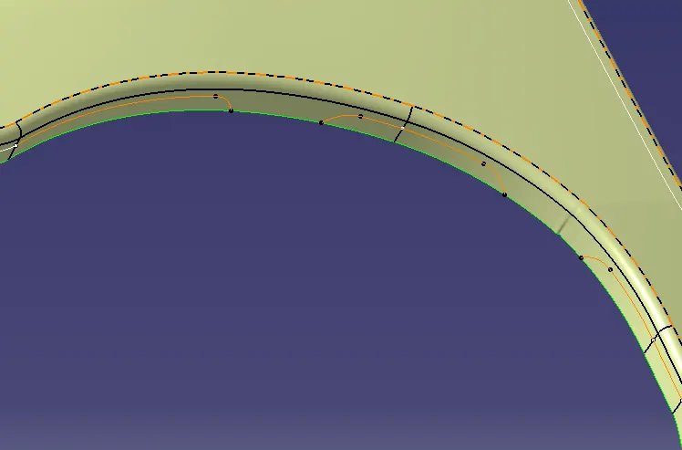
after spliting the parallel lines use join option to join it and split it off the skin data
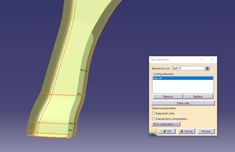
fender skin after spliting creates a mounting area for the require assembly or attachment.
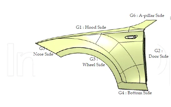
Master section to create the Drip Area :
first according to master section:
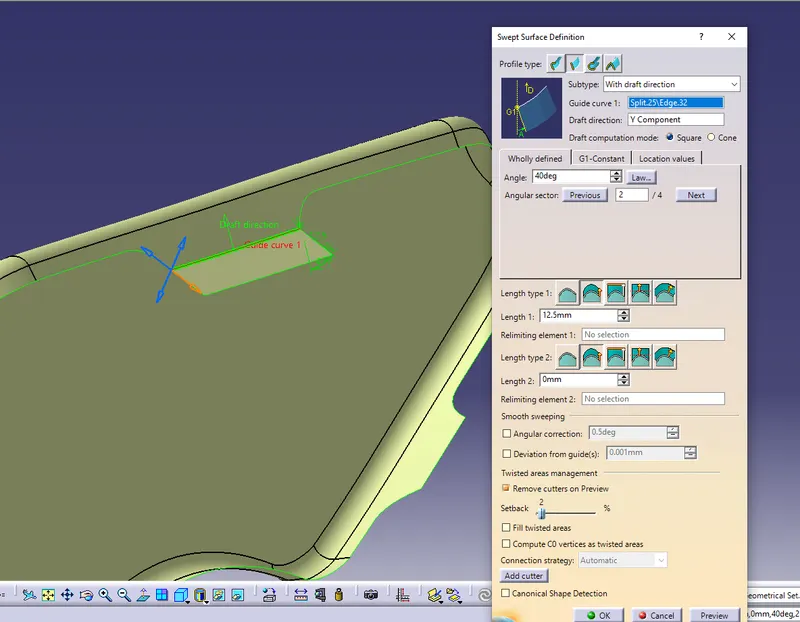
use sweep 40 deg length 12.5mm to get master section dimension of 8mm.
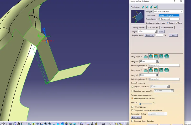
Again sweep 5 deg length 29mm to get master section of less than 40mm.
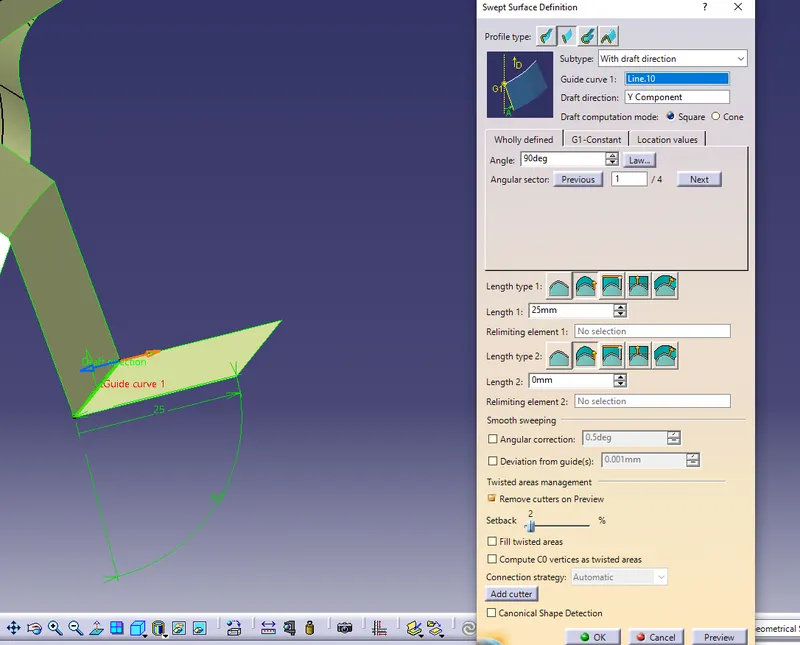
sweep edges of 5 deg was curve. so we require line to produce a straight surface.
for joining the surface we used trim option.
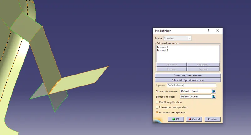
again the respective dimensions are given to produce the Drip area.
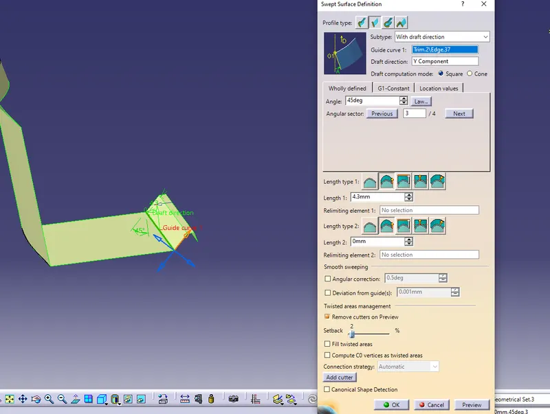
required fillets and edgefillet are provided.according to the master section.
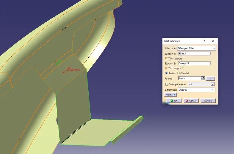
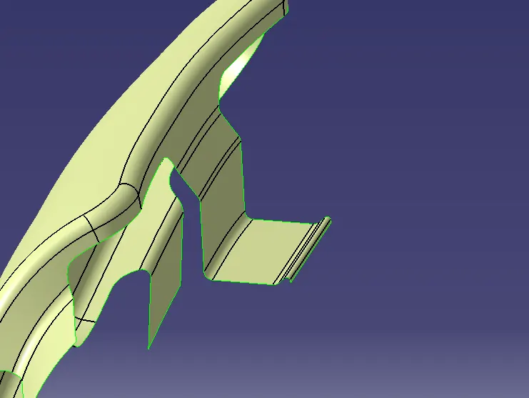
sketch for the drips area:
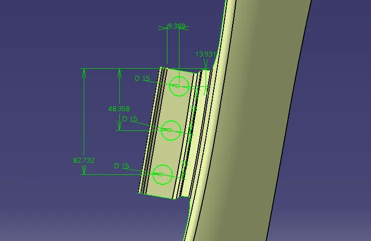
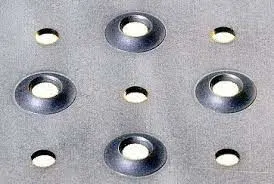
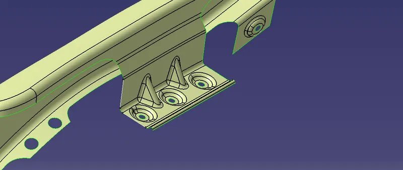
holes for drips:
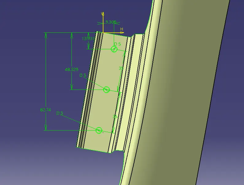
sweep the profile 8 deg and trim it with the extracted surface
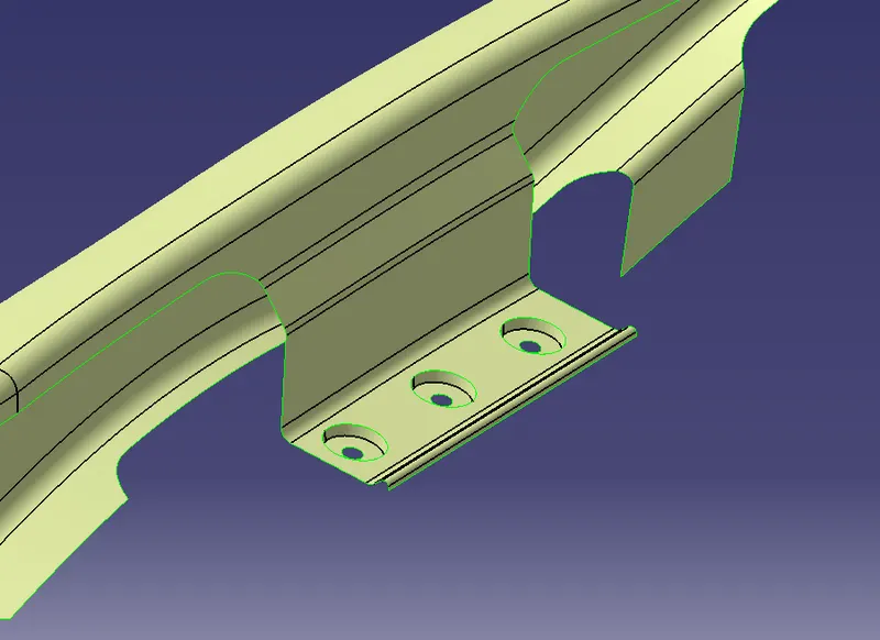
then give fillets:
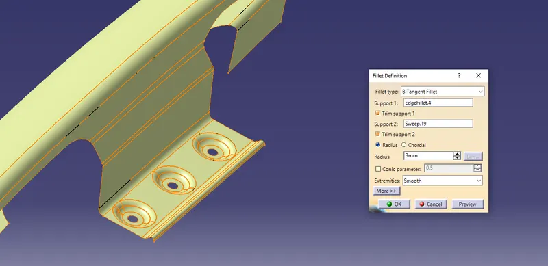
same respective method is used for other flange area also:
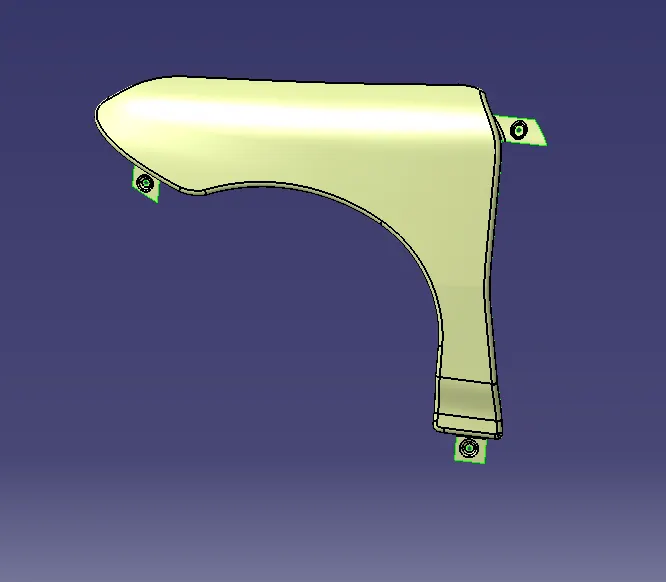
sfittness for the drip area:
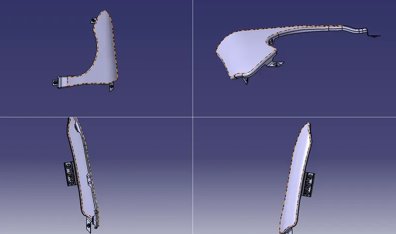
final fender surface:

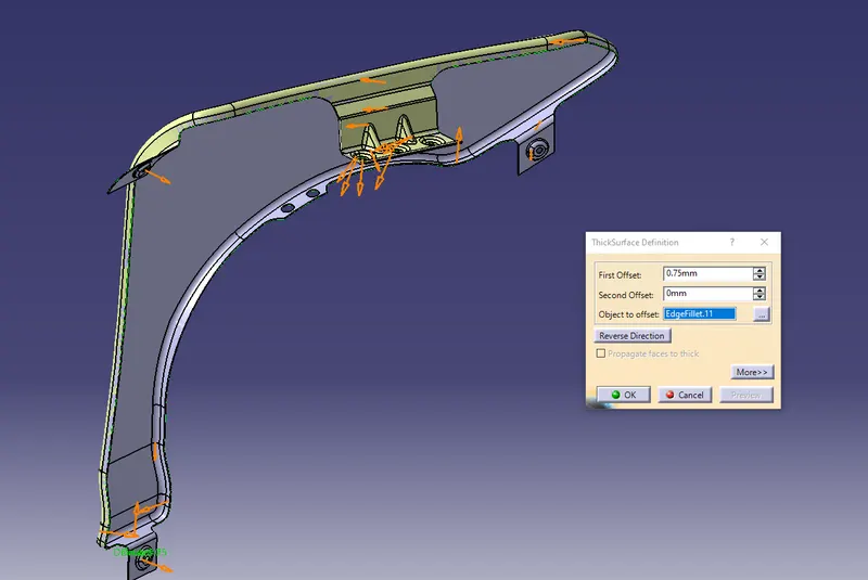
solid body using thick option: