Week 12:Project 2-Meshing of Rear Wheel Holder challenge
OBJECTIVE: To Follow the Quality Criteria and mesh the given sheet metal component and assign thickness to the components.
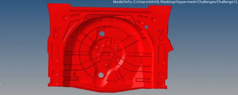
CAD MODEL IMAGE:
PROCEDURE:
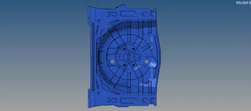
- The given model of the wheel holder is imported by the import model command.
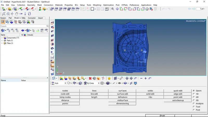
- The given component is divided into 2 parts for generating mid surface separately.
- Now the first portion of the divided component is moved into a different collector to generate midsurface.
- Now the mid surface of the first portion is extracted through offset command in auto misdurfacing method.
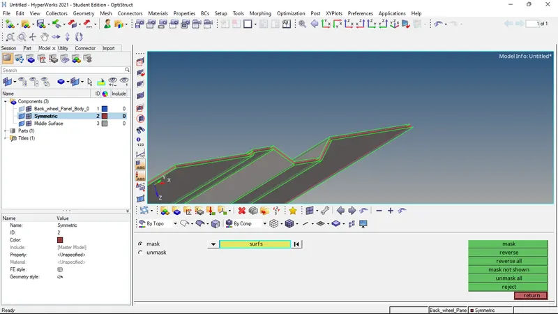
- Now manual cleanup of the midsurface is done.
- Then, meshing of the portion is done.
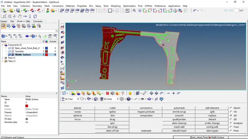
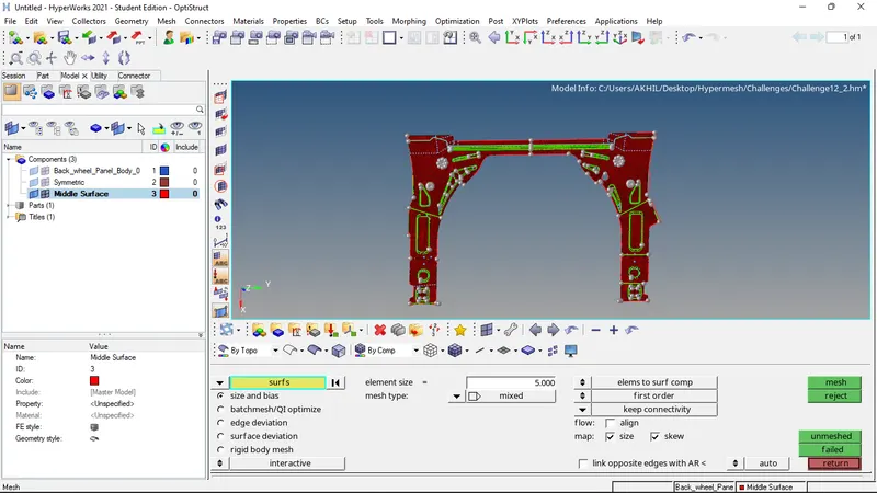
- Now mid surface of the middle portion in extracted.
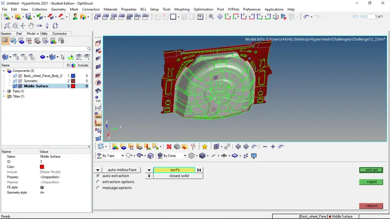
- Atfer mid surface extraction of the middle portion is extracted, the midsurfaces are joined by using toggle edge command.
- Then the cleanup of mis surface is done manually.
- Then the meshing of the surface is done.
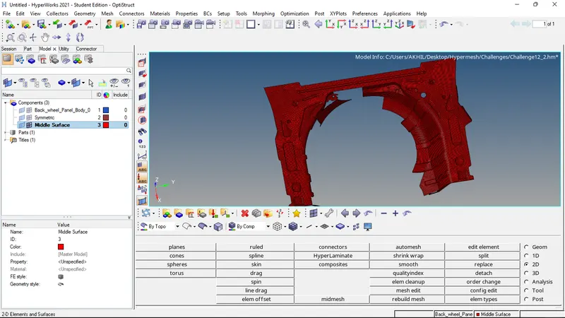
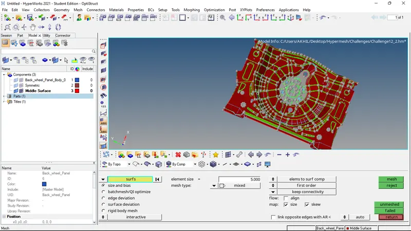
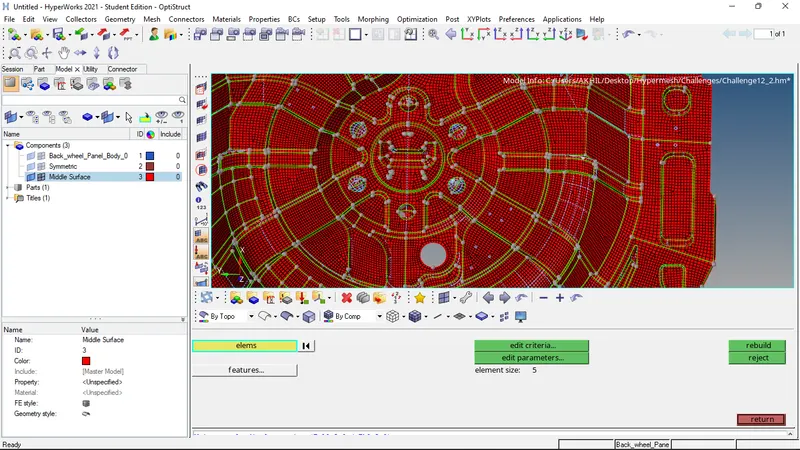
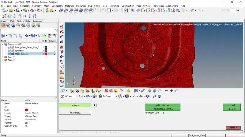
- For ensuring proper mesh flow, the elements are selected and remeshed.
- Then the tria elements are taken care of by split and combine commands.
- Nodes are aligned using align nodes command.
- The elements are projected on to a line or surface by project command.
- The elements are again remeshed to ensure proper mesh flow.
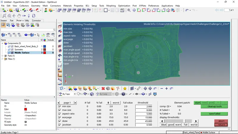
- Now the quality of the mesh is checked by the quality index command. The given quality threshold values are given and the quality of the mesh is evaluated.
- The elements which are failing the given criteria are then corrected by cleanup tools.
- Now check for edges, normals, dependency, and penetration is performed.
- Next properties are created and thickness is assigned to the properties.
- The properties and materials are then assigned to the component.
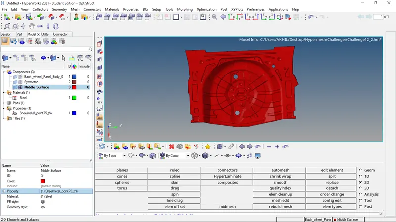
- Thus the meshing of the plastic component and thickness assignment is completed.
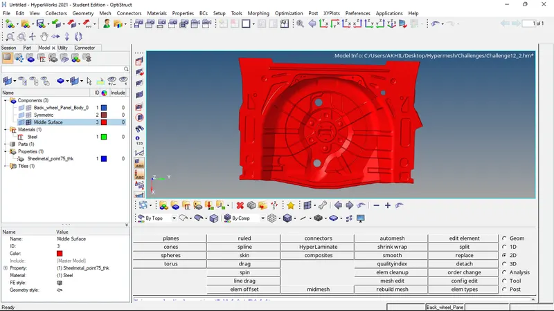
FINAL MODEL IMAGE: