Week 9-Creation of 1D Connectors Challenge
OBJECTIVE: To Perform mesh generation on the given components according to the given quality criterias and also to create connectors as mentioned.
CAD MODEL IMAGE:
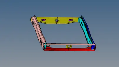
PROCEDURE:
- The given model is imported by the import model command.

- Mid surfaces of the component is already extracted so we can proceed to meshing of the components.
- Now properties are created and material is assigned to the property. Then properties are assigned to the corresponding components.
- Now, we will be performing the meshing of components.
- Geometry cleanup of the component is done before meshing.
- The given Quality criteria are given as input in the mesh criteria preference tab.
- First front truss 1 component of the assembly is selected for meshing.
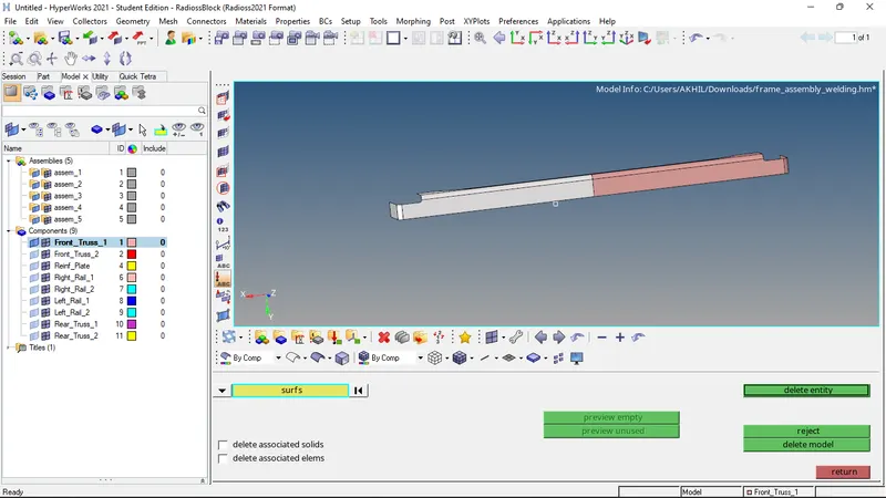
- As the part is symmetrical, one half of the model is meshed.
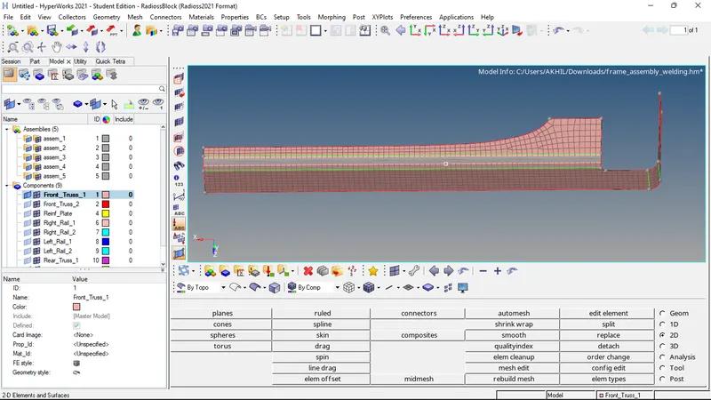
- For ensuring proper mesh flow, the elements are selected and remeshed.
- Then the tria elements are taken care of by split and combine commands.
- Nodes are aligned using align nodes command.
- The elements are projected on to a line or surface by project command.
- The elements are again remeshed to ensure proper mesh flow.
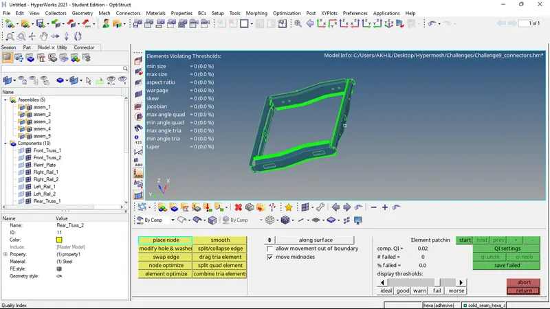
- Now the quality of the mesh is checked by the quality index command. The given quality threshold values are given and the quality of the mesh is evaluated.
- The elements which are failing the given criteria are then corrected by cleanup tools.
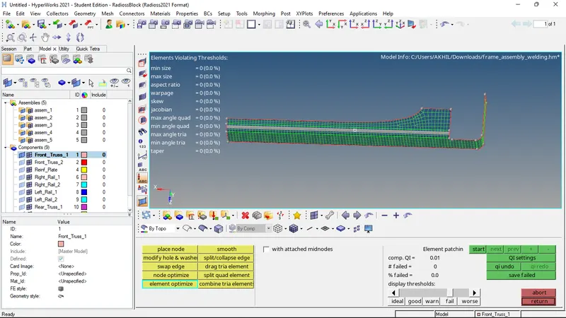
- Now check for edges, normals, dependency, and penetration is performed.
- Now that the mesh is proper the mesh is reflected to create the mesh of the entire component.
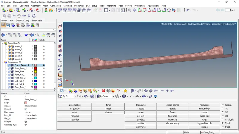
- Now that the meshing of first component is completed, the same procedure is followed to create mesh for the next 8 components.
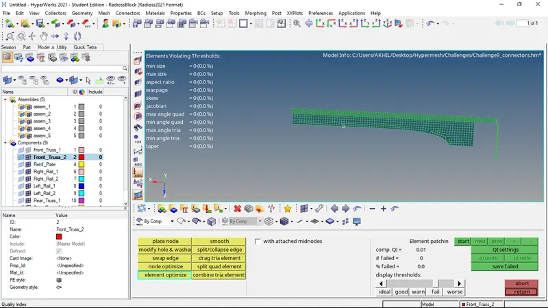
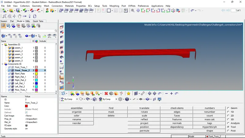
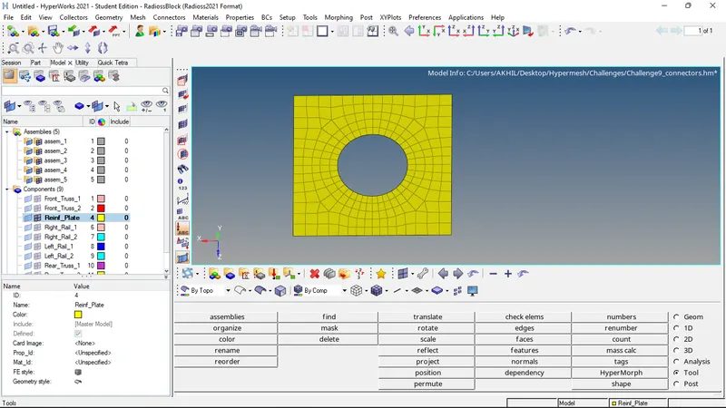
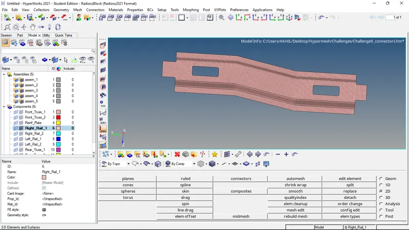
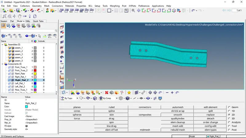
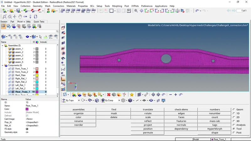
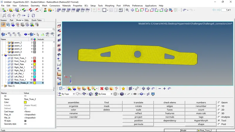
- Now the meshing of the entire components are completed.
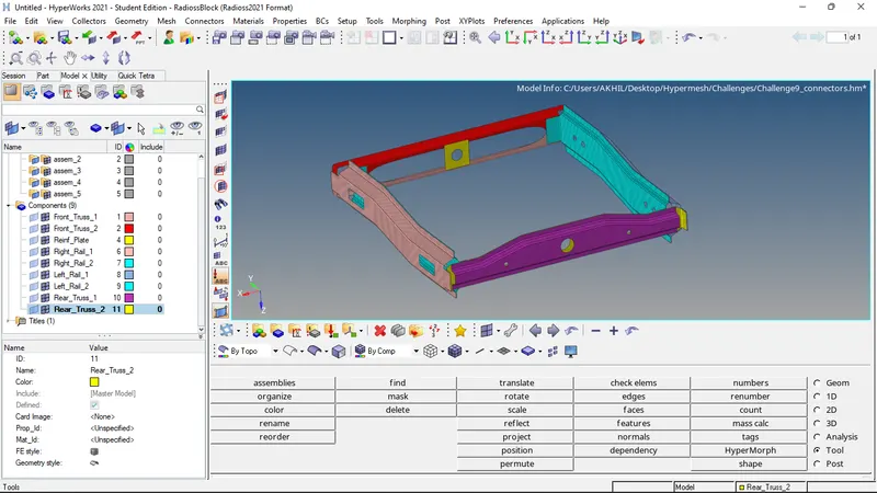
- Now connectors are to be provided as mentioned.
1. Right_Rail_2 & Front_truss_1:- Seam-Quad(angled+capped+L)
- For Seam-Quad(angled+capped+L), the option is selected from seam welding option and the required parameters are provided. i.e. spacing, height, cap angle , run off angle etc.
- Then the node list and the components between which the connector is to be provided is selected and then the connector is created.
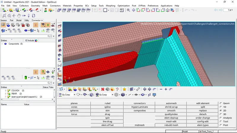
2. Left_Rail_2 & Front_truss_1:- Quad elements
- For quad elements connector, the option is selected from seam welding option and the required parameters are provided.
- Then the node list and the components between which the connector is to be provided is selected and then the connector is created.
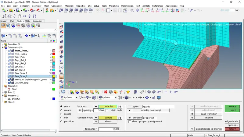
3. Front_truss_2, Front_truss_1 & Right_Rail_1:- Spot weld with 2 Layers and 5 mm Diameter
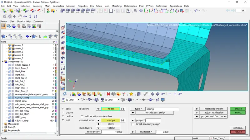
- For spot weld connector, the option is selected from spot welding option and the required parameters are provided.
- Then the node list and the components between which the connector is to be provided is selected and then the connector is created.
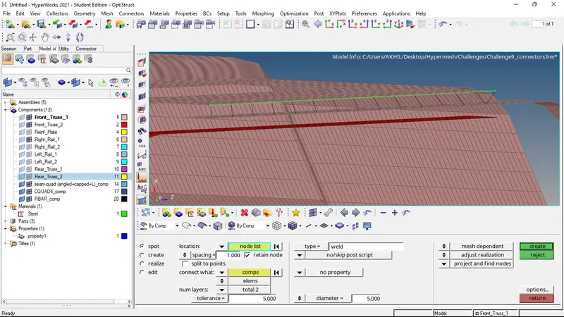
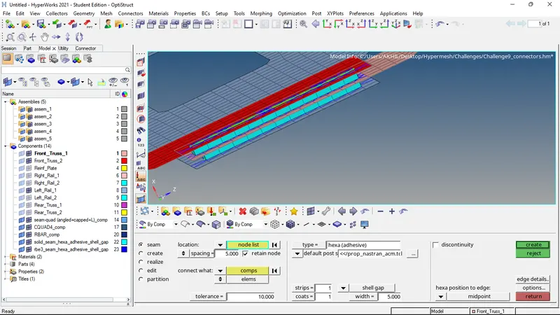
4. Front_truss_2, Front_truss_1 & Left_Rail_1:- Hexa (Adhesive)
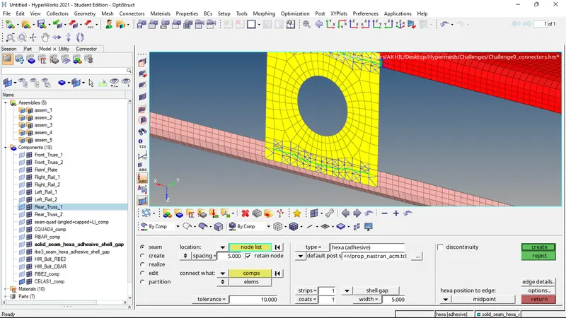
- For hexa adhesive connector, the option is selected from seam welding option and the required parameters are provided.
- Then the node list and the components between which the connector is to be provided is selected and then the connector is created.
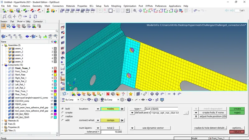
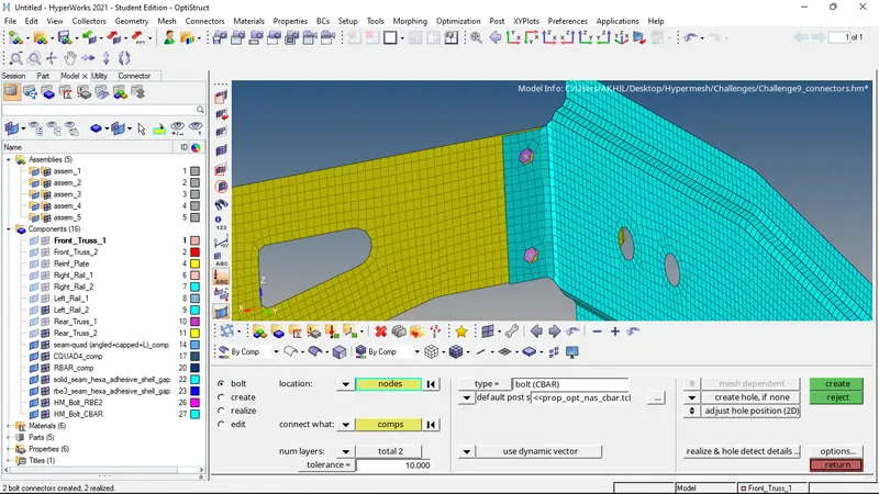
5. Rear_truss_2 & Right_Rail_2:- Bolt Connector
6. Rear_truss_2 & Left_Rail_2:- Bolt Connector
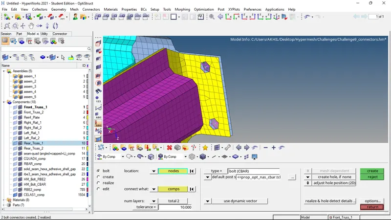
- Bolt connecters are created from bolt option from connectors tab.
- Required parameters ate given as input.
- The nodes are selected and mesh is generated.
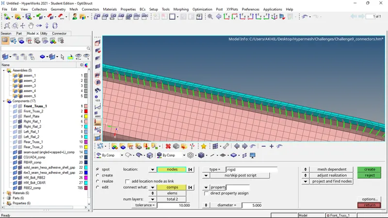
7. Right_Rail_1 & Right_Rail_2:- Spot-weld with Rigid Elements
- Rigid elements connector is given between right rail one and two.
8. Left_Rail_1 & Left_Rail_2:- Spot-weld with Spring Elements
- Spring element connector is given between left rail 1 and 2.
9. Rest of the components are connected using suitable connectors.
- Now the elements are checked for quality criteria and the failed elements are remeshed.
FINAL MODEL IMAGE:
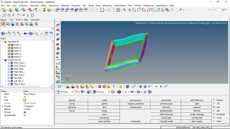
RESULTS: Mesh generation on the given components according to the given quality criteria and also the creation of connectors as mentioned are successfully completed.