Project 1 - 2D meshing on the instrumental Panel
I have attac hed drive link of the model due to the high file size.
CAD MODEL GOOGLE DRIVE LINK: https://drive.google.com/file/d/1rK1mSrP72XM5VYibQcXrQSOccx1jrAuZ/view?usp=sharing
OBJECTIVE: To check for the geometrical errors and mesh with the given element Quality criteria using align manager. And to assign the component the thickness.
CAD MODEL IMAGE:
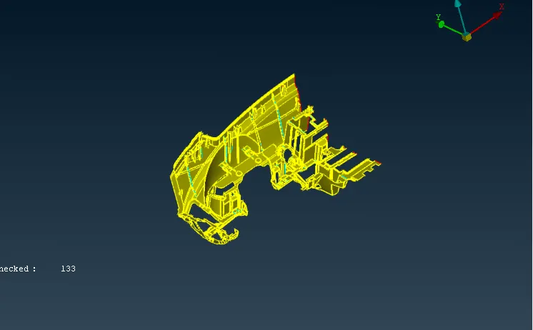
PROCEDURE:
- Align manger approach is used for the model.
- The given model of the dash board is imported by the open model command.
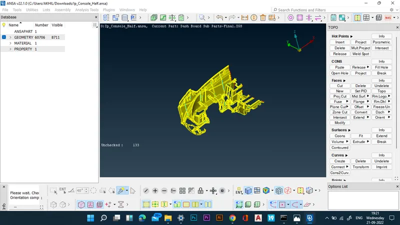
- The model is checked for geometrical errors first.
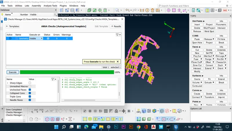
- Now that the model is free of errors, mid-surfacing and meshing of the of the model can be done through casting command.
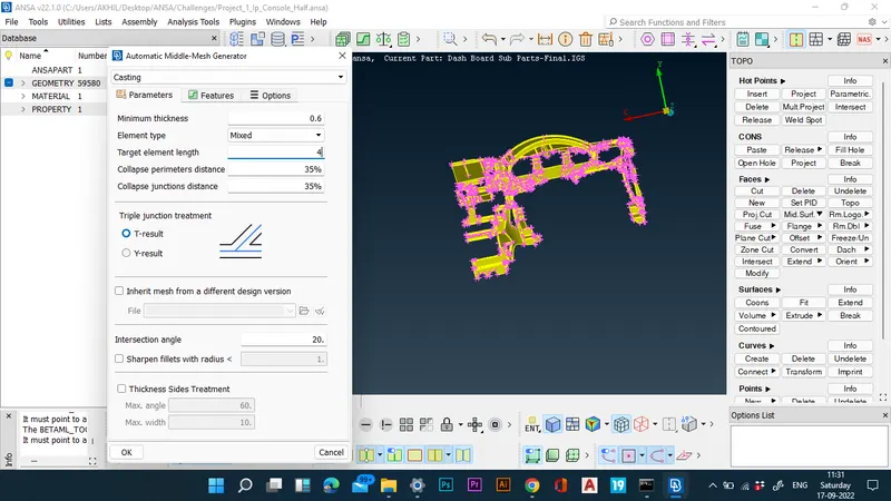
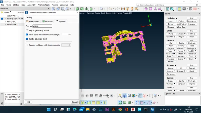
- Thus the auto midsurfacing and meshing of the component is done through casting command.
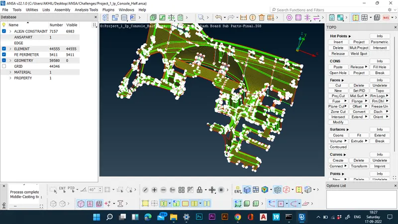
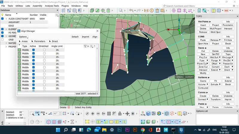
- Now the align manger option is opened and checked for empty features. i.e. features that were not captured properly.
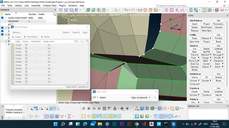
- The improperly captured features are also corrected by redefining them.
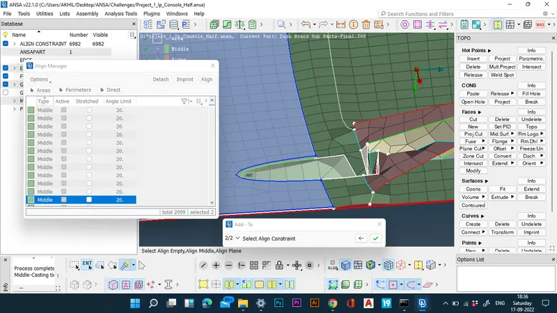
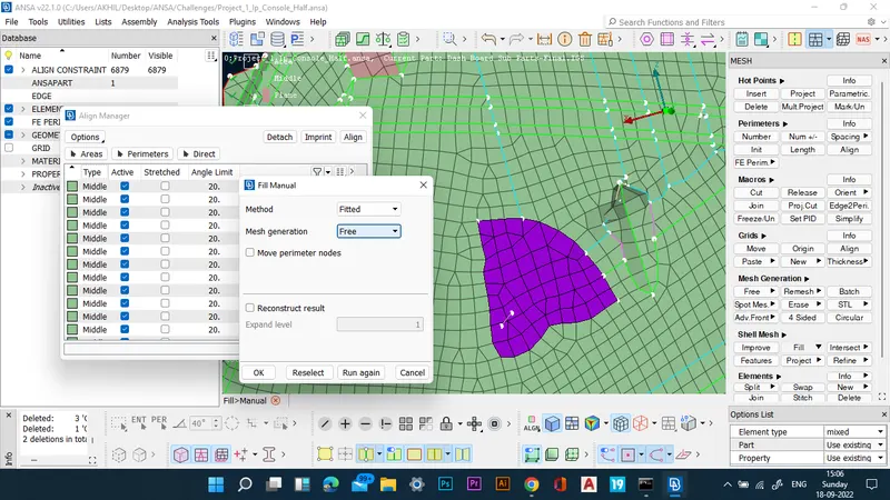
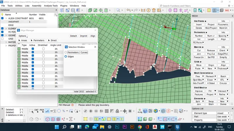
- The features which are still not properly captured are deleted and then it is filled manually.
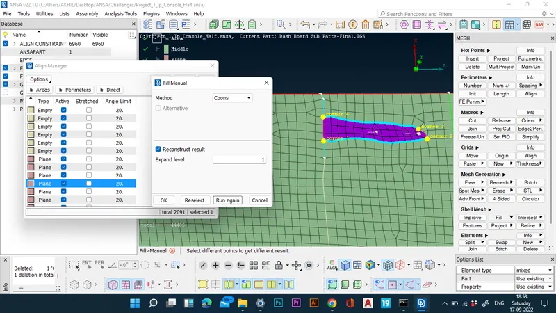
- The manually created shells are then assigned to a feature by using new middle/plane command in align manager.
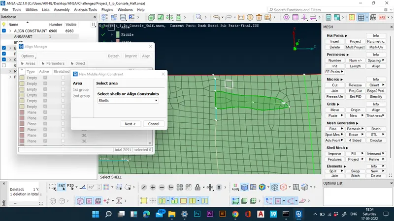
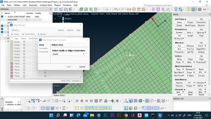
- The planes are also added to other features using the add to command.
- Now dog houses are checked whether they are captured properly and they are corrected.
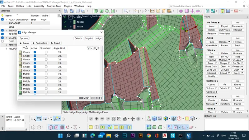
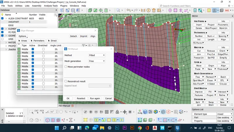
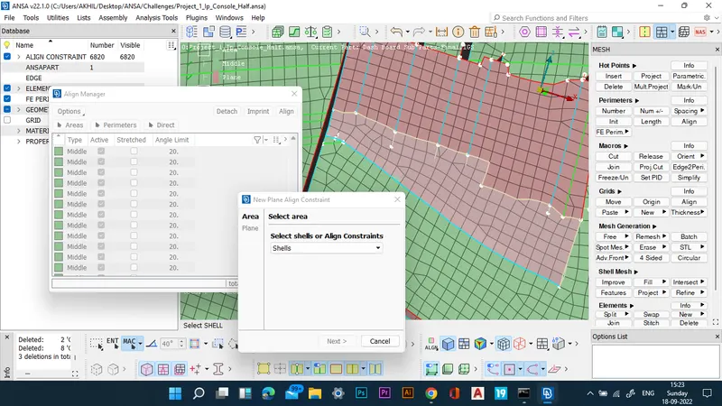
- The perimeters are also aligned using the align perimeter option in align manager.
- The above-mentioned operations are repeated for all the regions to ensure proper capturing.
- Now that meshing is complete, the mesh is checked for quality.
- The quality is then improved using restructure.
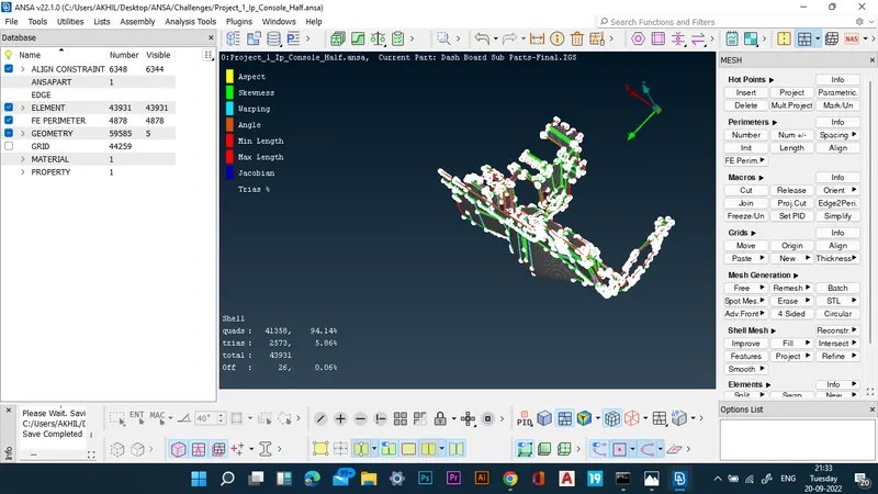
- Now the nodal properties are converted to thickness using the thickness convert command.
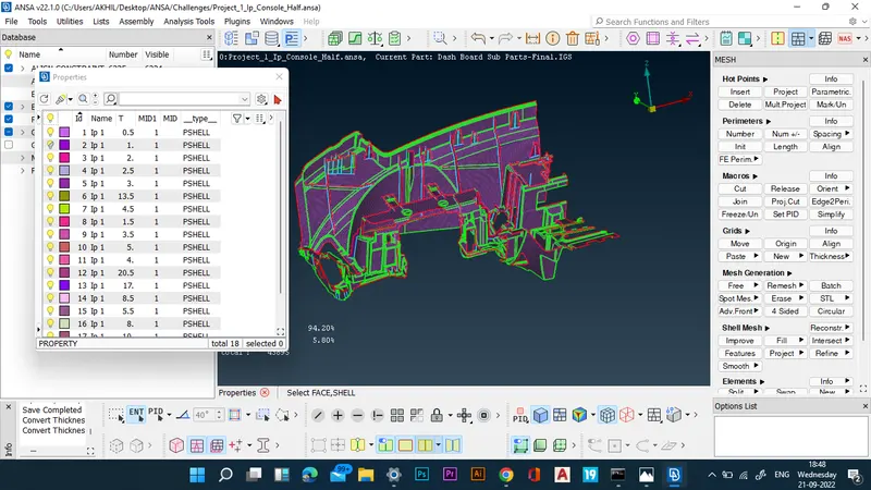
RESULTS: The meshing of the given dashboard component is completed successfully using align manager.
FINAL CAD IMAGE: