Week - 4 - 2D meshing for Plastic components
OBJECTIVE: To extract the mid surface for all the cap model after checking the geometrical errors and mesh the mid surface with the given element Quality criteria.
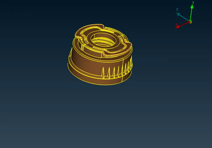
CAD MODEL IMAGE:
PROCEDURE:
- The given model of the cap is imported by the open model command.

- The model is checked for geometrical errors first.
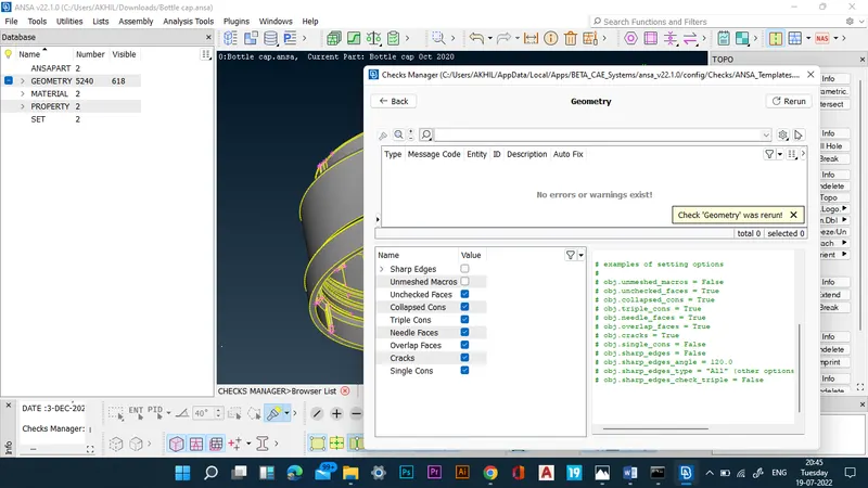
- Now that the model is free of errors, manual mid-surfacing of the model can be done.
- The mid-surface is generated by the manual mid-surfacing method.
- The thickness of each regions are measured and then the surfaces are offsetted to the middle.
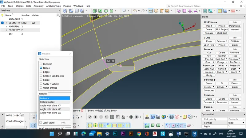
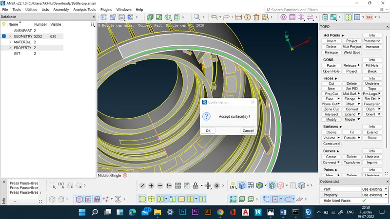
- The same procedure is done afor all the regions.
- the midsurface is then joined and corrected by making new faces in the gaps.
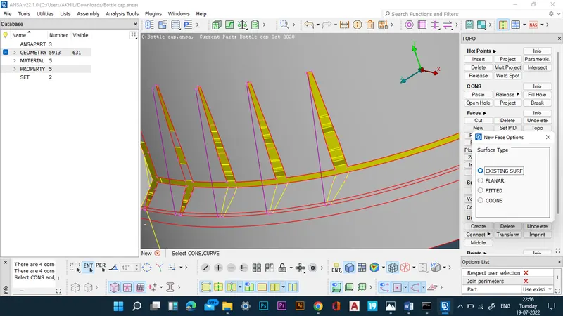
- The mid- surface of the ribs is generated by creating new face by cons command.
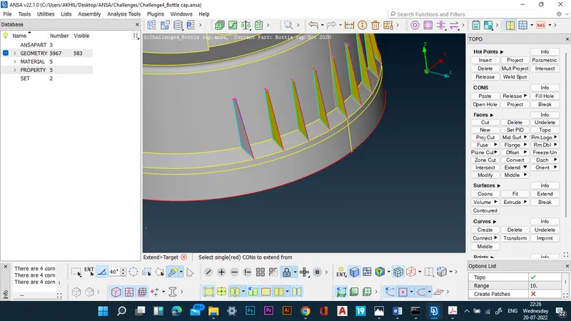
- Now to create the mid surface of the tread portion, the middle curve of the thread is generated, the it is projected on to the mid plane.
- Then the mid surface is generated by using new face command.
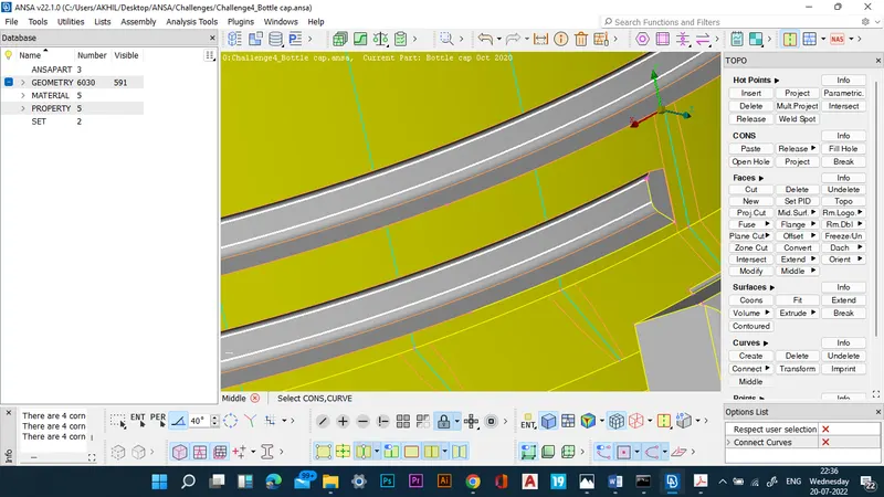
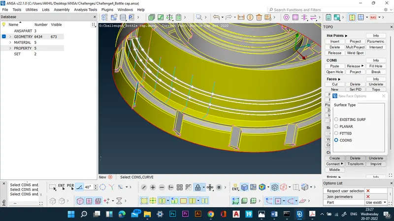
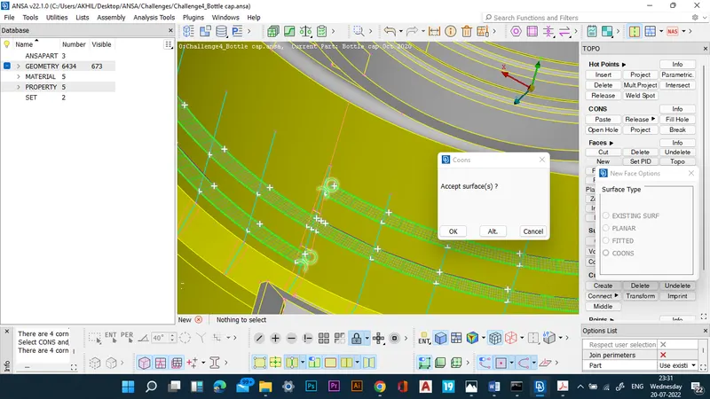
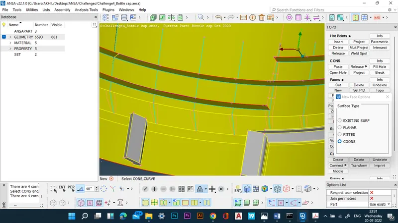
- Similarly, the mid surface is generated for all the regions.
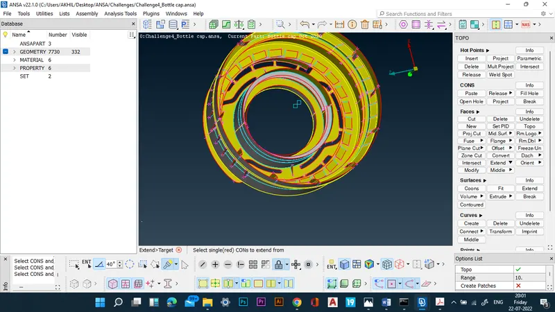
- Now that the component is ready for meshing, meshing is done by best mesh command.
- The quality criterias and meshing parameters are set at first.
- Then meshing of the component is done region by region.
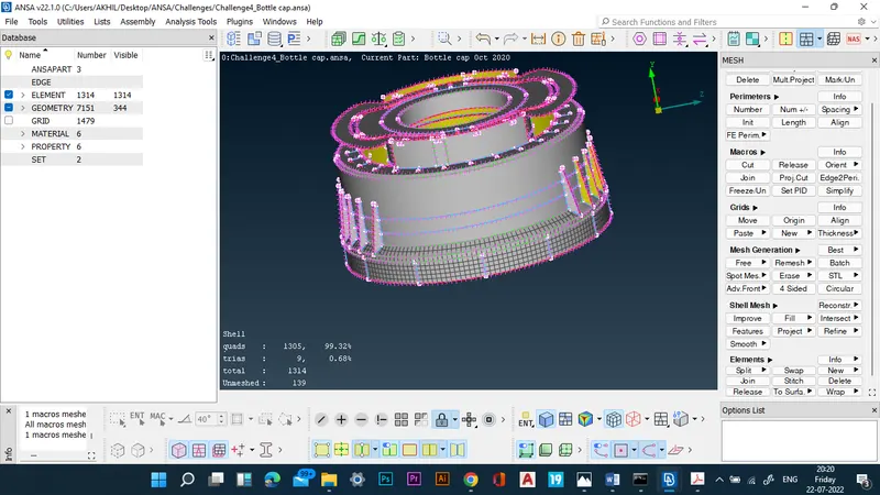
- For ensuring proper mesh flow, the elements are selected and remeshed using reconstruct command.
- Similarly all the regions are meshed.
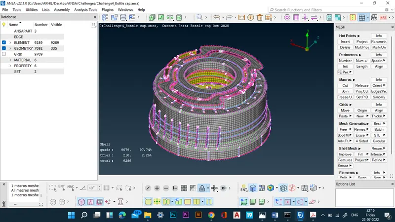
- Then the tria elements are taken care of by split command.
- Next, the quality criteria are given as input and checked.
- The quality criterias are checked and corrected.
- Now properties are assigned to each regions according to thickness.
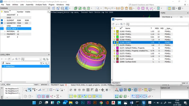
- After assigning the properties, the model is visualised in 'draw shell as solid command', to compare with parent geometry.
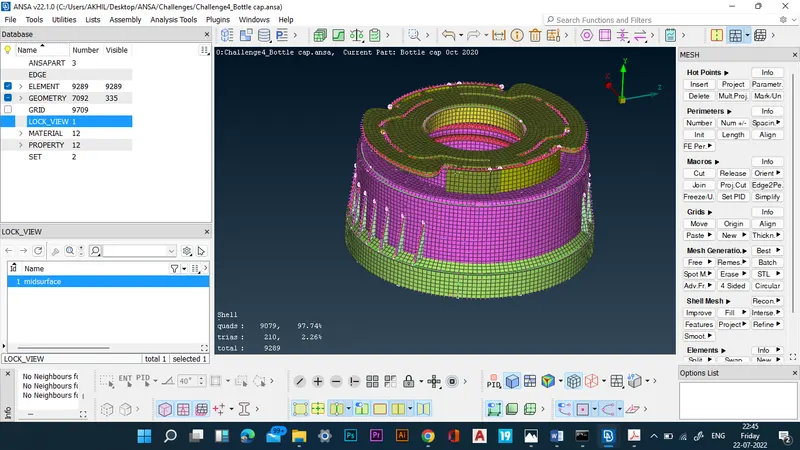
- Thus the meshing of the component is successfully completed and checked.
RESULTS: Mid-surface generation for the cap model after checking the geometrical errors and meshing of the component with the given element Quality criteria is successfully completed
FINAL CAD IMAGE: